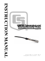
1
HMP60 Temperature and
Relative Humidity Probe
Revision: 7/12
C o p y r i g h t © 1 9 9 5 - 2 0 1 2
C a m p b e l l S c i e n t i f i c , I n c .
Warranty
“PRODUCTS MANUFACTURED BY CAMPBELL SCIENTIFIC, INC. are
warranted by Campbell Scientific, Inc. (“Campbell”) to be free from defects in
materials and workmanship under normal use and service for twelve (12)
months from date of shipment unless otherwise specified in the corresponding
Campbell pricelist or product manual. Products not manufactured, but that are
re-sold by Campbell, are warranted only to the limits extended by the original
manufacturer. Batteries, fine-wire thermocouples, desiccant, and other
consumables have no warranty. Campbell's obligation under this warranty is
limited to repairing or replacing (at Campbell's option) defective products,
which shall be the sole and exclusive remedy under this warranty. The
customer shall assume all costs of removing, reinstalling, and shipping
defective products to Campbell. Campbell will return such products by surface
carrier prepaid within the continental United States of America. To all other
locations, Campbell will return such products best way CIP (Port of Entry)
INCOTERM® 2010, prepaid. This warranty shall not apply to any products
which have been subjected to modification, misuse, neglect, improper service,
accidents of nature, or shipping damage. This warranty is in lieu of all other
warranties, expressed or implied. The warranty for installation services
performed by Campbell such as programming to customer specifications,
electrical connections to products manufactured by Campbell, and product
specific training, is part of Campbell’s product warranty. CAMPBELL
EXPRESSLY DISCLAIMS AND EXCLUDES ANY IMPLIED
WARRANTIES OF MERCHANTABILITY OR FITNESS FOR A
PARTICULAR PURPOSE. Campbell is not liable for any special, indirect,
incidental, and/or consequential damages.”
Assistance
Products may not be returned without prior authorization. The following
contact information is for US and international customers residing in countries
served by Campbell Scientific, Inc. directly. Affiliate companies handle
repairs for customers within their territories. Please visit
www.campbellsci.com to determine which Campbell Scientific company serves
your country.
To obtain a Returned Materials Authorization (RMA), contact CAMPBELL
SCIENTIFIC, INC., phone (435) 227-9000. After an applications engineer
determines the nature of the problem, an RMA number will be issued. Please
write this number clearly on the outside of the shipping container. Campbell
Scientific's shipping address is:
CAMPBELL SCIENTIFIC, INC.
RMA#_____
815 West 1800 North
Logan, Utah 84321-1784
For all returns, the customer must fill out a "Statement of Product Cleanliness
and Decontamination" form and comply with the requirements specified in it.
The form is available from our web site at www.campbellsci.com/repair. A
completed form must be either emailed to [email protected] or faxed to
(435) 227-9106. Campbell Scientific is unable to process any returns until we
receive this form. If the form is not received within three days of product
receipt or is incomplete, the product will be returned to the customer at the
customer's expense. Campbell Scientific reserves the right to refuse service on
products that were exposed to contaminants that may cause health or safety
concerns for our employees.
HMP60 Table of Contents
PDF viewers: These page numbers refer to the printed version of this document. Use the
PDF reader bookmarks tab for links to specific sections.
1. Introduction..................................................................1
2. Cautionary Statements................................................1
3. Initial Inspection ..........................................................1
4. Quickstart .....................................................................2
4.1 Step 1 — Mount the Probe .......................................................................2
4.2 Step 2 — Use SCWin Short Cut to Program Datalogger and
Generate Wiring Diagram......................................................................5
5. Overview.......................................................................7
6. Specifications ..............................................................8
6.1 Temperature Sensor ..................................................................................9
6.2 Relative Humidity Sensor.........................................................................9
7. Installation..................................................................10
7.1
7.2
7.3
7.4
Siting.......................................................................................................10
Mounting and Assembly.........................................................................10
Wiring.....................................................................................................11
Programming ..........................................................................................11
7.4.1 Example for CR1000 ....................................................................12
7.4.2 Example for CR10X .....................................................................13
7.5 Long Lead Lengths.................................................................................13
7.6 Absolute Humidity..................................................................................14
7.6.1 CR1000 Vapor Pressure Example.................................................15
7.6.2 Sample CR10(X) Program that Computes Vapor Pressure
and Saturation Vapor Pressure ..................................................16
8. Maintenance ...............................................................17
8.1 Procedure for Removing RH Chip .........................................................17
9. Troubleshooting ........................................................18
10. References ...............................................................18
i
HMP60 Table of Contents
Figures
4-1.
4-2.
4-3.
4-4.
7-1.
8-1.
HMP60 as shipped.................................................................................. 3
HMP60 and 41303-5A Radiation Shield on a tripod mast ..................... 3
HMP60 and 41303-5A Radiation Shield on a CM202 Crossarm........... 4
HMP60 and 41303-5A Radiation Shield................................................ 4
HMP60 wiring ...................................................................................... 11
Exploded view of HMP60 (as shipped)................................................ 17
5-1.
7-1.
7-2.
7-3.
7-4.
7-5.
Recommended Lead Lengths ................................................................. 8
Datalogger Connections ....................................................................... 11
Calibration for Temperature ................................................................. 12
Calibration for Relative Humidity ........................................................ 12
Wiring for CR1000 and CR10X Examples .......................................... 12
Wiring for Vapor Pressure Examples ................................................... 15
Tables
ii
HMP60 Temperature and Relative
Humidity Probe
1. Introduction
The HMP60 probe measures temperature for the range of -40° to 60°C, and
relative humidity for the range of 0 to 100% RH. It is suitable for long-term,
unattended monitoring, and is compatible with all Campbell Scientific
dataloggers.
Before using the HMP60, please study
•
•
•
Section 2, Cautionary Statements
Section 3, Initial Inspection
Section 4, Quickstart
More details are available in the remaining sections.
2. Cautionary Statements
•
Care should be taken when opening the shipping package to not damage
or cut the cable jacket. If damage to the cable is suspected, consult with a
Campbell Scientific applications engineer.
•
Although the HMP60 is rugged, it should be handled as a precision
scientific instrument.
•
The black outer jacket of the cable is Santoprene® rubber. This
compound was chosen for its resistance to temperature extremes, moisture,
and UV degradation. However, this jacket will support combustion in air.
It is rated as slow burning when tested according to U.L. 94 H.B. and will
pass FMVSS302. Local fire codes may preclude its use inside buildings.
•
Remember to remove the yellow cap prior to installation.
3. Initial Inspection
•
Upon receipt of the HMP60, inspect the packaging and contents for
damage. File damage claims with the shipping company.
•
The model number and cable length are printed on a label at the
connection end of the cable. Check this information against the shipping
documents to ensure the correct product and cable length are received.
•
The HMP60 is shipped with an instruction manual or a ResourceDVD.
1
HMP60 Temperature and Relative Humidity Probe
4. Quickstart
4.1 Step 1 — Mount the Probe
Review Section 7, Installation for complete instructions. To install the
HMP60, you will need:
•
•
•
•
•
•
CAUTION
2
41305-5A 6-plate Radiation Shield
1/2" open end wrench
small screw driver provided with datalogger
small Phillips screwdriver
UV resistant cable ties
small pair of diagonal-cutting pliers
1.
Pull off the yellow shipping cap (see Figure 4-1).
2.
Loosen the plastic split collar at the base of the shield (reversing the
removable portion if necessary) and gently insert the probe.
3.
Tighten the mounting clamp until it lightly grips the probe body (see
Figure 4-4).
4.
Continue to push the probe up into the body of the shield until the step in
the tube stops it from going any further.
5.
Tighten the collar until it securely grips the probe (see Figure 4-4).
6.
Attach the radiation shield to the tripod mast, crossarm, or tower leg using
the supplied U-bolt. See Figures 4-2 and 4-3 for examples of shield
mounting.
7.
Route the cable to the datalogger, and secure the cable to the mounting
structure using cable ties.
Failure to secure the cable can lead to breakage of the
wires due to fatigue if the cable is allowed to blow back
and forth in the wind.
HMP60 Temperature and Relative Humidity Probe
Yellow Shipping Cap
(remove before
installation)
FIGURE 4-1. HMP60 as shipped
FIGURE 4-2. HMP60 and 41303-5A Radiation Shield
on a tripod mast
3
HMP60 Temperature and Relative Humidity Probe
FIGURE 4-3. HMP60 and 41303-5A Radiation Shield
on a CM202 Crossarm
Mounting Clamp
FIGURE 4-4. HMP60 and 41303-5A Radiation Shield
4
HMP60 Temperature and Relative Humidity Probe
4.2 Step 2 — Use SCWin Short Cut to Program Datalogger and
Generate Wiring Diagram
The simplest method for programming the datalogger to measure the HMP60
is to use Campbell Scientific's SCWin Short Cut Program Generator.
1.
Open Short Cut and click on New Program.
2.
Select a datalogger and scan interval.
5
HMP60 Temperature and Relative Humidity Probe
6
3.
Select HMP50/HMP60 Temperature and Relative Humidity Sensor
then click the right arrow to add it to the list of sensors to be measured.
4.
Define the name of the public variables. Variables default to AirTC and
RH that hold the air temperature and relative humidity measurements.
Select the desired units of measure. Units default to Deg C.
HMP60 Temperature and Relative Humidity Probe
5.
Choose the outputs for the AirTC and RH and then select finish.
6.
Wire according to the wiring diagram generated by SCWin Short Cut.
5. Overview
The HMP60 Temperature and Relative Humidity probe contains a Platinum
Resistance Temperature detector (PRT) and a Vaisala INTERCAP® capacitive
relative humidity sensor.
The -L option on the model HMP60 Temperature and Relative Humidity probe
(HMP60-L) indicates that the cable length is user specified. Cable length is
specified when the sensor is ordered. Table 5-1 gives the recommended cable
length. This manual refers to the sensor as the HMP60.
7
HMP60 Temperature and Relative Humidity Probe
TABLE 5-1. Recommended Lead Lengths
2 m Height
Atop a tripod or tower via a 2 ft crossarm such as the CM202
Mast/Leg
CM202
CM6
CM10
CM110
CM115
CM120
UT10
UT20
UT30
9'
11'
11'
14'
14'
19'
24'
14'
24'
37'
Note: Add two feet to the cable length if you are mounting the enclosure on the leg base of a light-weight tripod.
The probe’s cable can terminate in:
•
•
•
•
Pigtails that connect directly to a Campbell Scientific datalogger
(option –PT).
Connector that attaches to a prewired enclosure (option –PW). Refer
to www.campbellsci.com/prewired-enclosures for more information.
Connector that attaches to a CWS900 Wireless Sensor Interface
(option –CWS). The CWS900 allows the probe to be used in a
wireless sensor network. Refer to www.campbellsci.com/cws900 for
more information.
Connector that attaches to a CS110 Electric Field Meter or an ETseries weather station (option –C). Refer to
www.campbellsci.com/cs110-sensor for more information.
6. Specifications
Features:
•
Field -replaceable humidity chip eliminates recalibration down time
•
Compatible with all Campbell Scientific dataloggers (including the
CR200(X) series)
•
Compatible with the CWS900-series interfaces, allowing it to be used
in a wireless sensor network
Compatibility
Dataloggers:
8
CR200(X) series
CR800 series
CR1000
CR3000
CR5000
CR9000(X)
CR7X
CR510
CR10(X)
CR23X
21X
Operating Temperature:
-40° to +60°C
Probe Length:
7.1 cm (2.8 in)
HMP60 Temperature and Relative Humidity Probe
Probe Body Diameter:
1.2 cm (0.47 in)
Filter:
0.2 μm Teflon membrane
Filter Diameter:
1.2 cm (0.47 in)
Housing
Body Material:
Filter Cap Material:
Classification:
AISI 316 stainless steel
Chrome-coated ABS plastic
IP65
Power Consumption:
1 mA typical; 5 mA maximum
Supply Voltage:
5 to 28 Vdc
Settling Time after
power is switched on:
1 second
Output Signal Range:
0 to 1 Vdc
6.1 Temperature Sensor
Sensor:
1000 Ω PRT, DIN 43760B
Temperature
Measurement Range:
-40° to +60°C
Temperature Accuracy:
±0.6°C (-40° to +60°C)
6.2 Relative Humidity Sensor
Sensor:
INTERCAP®
Relative Humidity
Measurement Range:
0 to 100% non-condensing
Accuracy at 0° to +40°C:
Accuracy at -40° to 0°C
and +40° to +60°C:
CAUTION
±3% RH (0 to 90% Relative Humidity)
±5% RH (90 to 100% Relative Humidity)
±5% RH (0 to 90% Relative Humidity)
±7% RH (90 to 100% Relative Humidity)
The black outer jacket of the cable is Santoprene® rubber.
This compound was chosen for its resistance to
temperature extremes, moisture, and UV degradation.
However, this jacket will support combustion in air. It is
rated as slow burning when tested according to U.L. 94
H.B. and will pass FMVSS302. Local fire codes may
preclude its use inside buildings.
9
HMP60 Temperature and Relative Humidity Probe
7. Installation
7.1 Siting
Sensors should be located over an open level area at least 9 m (EPA) in
diameter. The surface should be covered by short grass, or where grass does
not grow, the natural earth surface. Sensors should be located at a distance of
at least four times the height of any nearby obstruction, and at least 30 m
(EPA) from large paved areas. Sensors should be protected from thermal
radiation, and adequately ventilated.
Standard measurement heights:
1.5 m (AASC)
1.25 – 2.0 m (WMO)
2.0 m (EPA)
See Section 10 for a list of references that discuss temperature and relative
humidity sensors.
7.2 Mounting and Assembly
Pull off the yellow shipping cap (see Figure 4-1 in Section 4, Quickstart).
The HMP60 must be housed inside a solar radiation shield when used in the
field. The HMP60 is typically housed in the 41303-5A 6-Plate Radiation
Shield (Figures 4-2 and 4-3 in Section 4, Quickstart). The HMP60 is held
within the 41303-5A by a mounting clamp (Figure 4-4 in Section 4,
Quickstart).
This probe may also be housed in a 41003-5 10-plate shield if additional
hardware is used. A 41322 Adapter Plate allows the HMP60 to be mounted in
the lower part of the 41003-5 10-plate shield. Alternatively, a 41381 extension
tube and the 6637 split nut plug can be used to mount the HMP60 in a higher
part of the 41003-5; the #41381 cable is also required.
Both the 41303-5A and the 41003-5 attach to a crossarm, mast, or usersupplied pipe with a 1.0-in. to 2.1-in. outer diameter.
10
HMP60 Temperature and Relative Humidity Probe
Black
Temperature Signal
White
Relative Humidity Signal
Blue
Signal & Power Reference
Brown
Power
Clear
Shield
FIGURE 7-1. HMP60 wiring
TABLE 7-1. Datalogger Connections
Wire Label
Temp Signal
RH Signal
Power & Signal
Ground
Power 12V
Shield
CR800, CR3000,
CR200(X), CR23X,
CR1000
Single-Ended Input
Single-Ended Input
G
Color
Black
White
Blue
Brown
Clear
12 V
CR10(X), CR510
Single-Ended Input
Single-Ended Input
G
21X, CR7
Single-Ended Input
Single-Ended Input
12 V
G
12 V
7.3 Wiring
Connections to Campbell Scientific dataloggers are given in Table 7-1. The
probe is measured by two single-ended analog input channels, one for
temperature and one for relative humidity.
CAUTION
Always connect the blue lead to the datalogger first,
followed by the black, white, and clear leads. Connect the
brown (power) lead last.
7.4 Programming
This section is for users who write their own datalogger programs. A
datalogger program to measure this sensor can be created using Campbell
Scientific’s Short Cut Program Builder Software. You do not need to read this
section to use Short Cut.
11
HMP60 Temperature and Relative Humidity Probe
The temperature and relative humidity signals from the HMP60 are measured
using two single-ended analog measurements (VoltSE() in CRBasic or
Instruction 1 in Edlog).
The probe output scale is 0 to 1000 millivolts for the temperature range of
-40° to +60°C and for the relative humidity range of 0 to 100%. Tables 7-2
and 7-3 provide calibration information for temperature and relative humidity.
TABLE 7-2. Calibration for Temperature
Units
Celsius
Fahrenheit
Multiplier
(degrees mV-1)
0.1
0.18
Offset
(degrees)
-40
-40
TABLE 7-3. Calibration for Relative Humidity
Units
Percent
Fraction
Multiplier
(% mV-1)
0.1
0.001
Offset
(%)
0
0
TABLE 7-4. Wiring for CR1000 and CR10X Examples
Description
Temperature
Relative Humidity
Signal & Power Reference
Power
Shield
Color
Black
White
Blue
Brown
Clear
CR1000
SE 1
SE 2
G
12 V
CR10(X)
SE 3 (2H)
SE 4 (2L)
G
12 V
G
7.4.1 Example for CR1000
'CR1000
'Created by SCWIN (2.1)
Public AirTC
Public RH
DataTable(Table1,True,-1)
DataInterval(0,60,Min,0)
Average(1,AirTC,FP2,0)
Sample(1,RH,FP2)
EndTable
BeginProg
Scan(5,Sec,1,0)
'HMP60 Temperature & Relative Humidity Sensor measurements AirTC and RH:
VoltSE(AirTC,1,mV2500,1,0,0,_60Hz,0.1,-40.0)
VoltSE(RH,1,mV2500,2,0,0,_60Hz,0.1,0)
If (RH>100) And (RH<108) Then RH=100
CallTable(Table1)
NextScan
EndProg
12
HMP60 Temperature and Relative Humidity Probe
7.4.2 Example for CR10X
;Measure the HMP60 temperature.
;
01: Volt (SE) (P1)
1: 1
Reps
2: 5
2500 mV Slow Range
3:
4:
5:
6:
3
1
.1
-40
SE Channel
Loc [ T_C
Mult
Offset
]
;See Table 7-2 for alternate multipliers
;See Table 7-2 for alternate offsets
;Measure the HMP60 relative humidity.
;
02: Volt (SE) (P1)
1: 1
Reps
2: 5
2500 mV Slow Range
3:
4:
5:
6:
4
3
.1
0
;CR510 (2500 mV); CR23X (1000 mV); 21X,
CR7 (5000 mV)
;Black wire (SE 3), Blue wire (G)
SE Channel
Loc [ RH_pct
Mult
Offset
;CR510 (2500 mV); CR23X (1000 mV); 21X,
CR7 (5000 mV)
;White wire (SE 4), Blue wire (G)
]
;See Table 7-3 for alternate multipliers
;Limit the maximum relative humidity to 100%.
;
03: If (X<=>F) (P89)
1: 3
X Loc [ RH_pct ]
2: 3
>=
3: 100
F
4: 30
Then Do
04: Z=F (P30)
1: 100
2: 0
3: 3
F
Exponent of 10
Z Loc [ RH_pct
]
05: End (P95)
7.5 Long Lead Lengths
Long lead lengths cause errors in the measured temperature and relative
humidity. The approximate error in temperature and relative humidity is
0.52°C and 0.52% per 100 feet of cable length, respectively.
When long lead lengths are required and the above errors in temperature and
relative humidity are unacceptable, use the HC2S3 or HMP155A temperature
and humidity probe.
Understanding the following details are not required for the general operation
of the HMP60 with Campbell Scientific’s dataloggers. The signal reference
and the power ground (black) are the same lead in the HMP60. When the
HMP60 temperature and relative humidity are measured, both the signal
13
HMP60 Temperature and Relative Humidity Probe
reference and power ground are connected to ground at the datalogger. The
signal reference/power ground lead serves as the return path for 12 V. There
will be a voltage drop along this lead because the wire itself has resistance. The
HMP60 draws approximately 2 mA when it is powered. The wire used in the
HMP60 (P/N 18159) has resistance of 26.2 Ω/1000 feet. Using Ohm’s law, the
voltage drop (Vd), along the signal reference/power ground lead, is given by
Eq. (1).
Vd
= I ∗R
= 2 mA ∗ 26.2 Ω 1000 ft
(1)
= 52.4 mV 1000 ft
This voltage drop will raise the apparent temperature and relative humidity
because the difference between the signal and signal reference, at the
datalogger, has increased by Vd.
7.6 Absolute Humidity
The HMP60 measures the relative humidity. Relative humidity is defined by
the equation below:
RH =
e
∗ 100
es
(2)
where RH is the relative humidity, e is the vapor pressure in kPa , and es is the
saturation vapor pressure in kPa. The vapor pressure, e, is an absolute measure
of the amount of water vapor in the air and is related to the dew point
temperature. The saturation vapor pressure is the maximum amount of water
vapor that air can hold at a given air temperature. The relationship between
dew point and vapor pressure, and air temperature and saturation vapor
pressure are given by Goff and Gratch (1946), Lowe (1977), and Weiss
(1977).
When the air temperature increases, so does the saturation vapor pressure.
Conversely, a decrease in air temperature causes a corresponding decrease in
saturation vapor pressure. It follows then from Eq. (2) that a change in air
temperature will change the relative humidity, without causing a change in
absolute humidity.
For example, for an air temperature of 20°C and a vapor pressure of 1.17 kPa,
the saturation vapor pressure is 2.34 kPa and the relative humidity is 50%. If
the air temperature is increased by 5°C and no moisture is added or removed
from the air, the saturation vapor pressure increases to 3.17 kPa and the
relative humidity decreases to 36.9%. After the increase in air temperature,
there is more energy available to vaporize the water. However, the actual
amount of water vapor in the air has not changed. Thus, the amount of water
vapor in the air, relative to saturation, has decreased.
Because of the inverse relationship between relative humidity and air
temperature, finding the mean relative humidity is meaningless. A more useful
quantity is the mean vapor pressure. The mean vapor pressure can be
computed on-line by the datalogger. CRBasic dataloggers use the
14
HMP60 Temperature and Relative Humidity Probe
VaporPressure() instruction to calculate vapor pressure from temperature and
relative humidity measurements (see Section 7.6.1). Edlog dataloggers must
first calculate the saturation vapor pressure and then calculate vapor pressure
(see Section 7.6.2).
TABLE 7-5. Wiring for Vapor Pressure Examples
Description
Temperature
Relative Humidity
Signal & Power Reference
Power
Shield
Color
Black
White
Blue
Brown
Clear
CR10(X)
SE 3 (2H)
SE 4 (2L)
G
12 V
G
CR1000
SE 1 (1H)
SE 2 (2H)
G
12 V
7.6.1 CR1000 Vapor Pressure Example
The VaporPressure() instruction has the following syntax:
VaporPressure(Dest,Temp,RH)
Where:
Dest—the variable in which the results of the instruction will be stored.
Temp—the program variable that contains the value for the temperature sensor.
The temperature measurement must be in degrees Celsius.
RH—the program variable that contains the value for the relative humidity
sensor. The relative humidity measurement must be in percent of RH.
'CR1000
Public AirTC
Public RH
Public VP
DataTable(Table1,True,-1)
DataInterval(0,60,Min,0)
Average(1,AirTC,FP2,0)
Sample(1,RH,FP2)
Average(1,VP, FP2,0)
EndTable
BeginProg
Scan(5,Sec,1,0)
'HMP60 Temperature & Relative Humidity Sensor measurements AirTC and RH:
VoltSE(AirTC,1,mV2500,1,0,0,_60Hz,0.1,-40.0)
VoltSE(RH,1,mV2500,2,0,0,_60Hz,0.1,0)
If (RH>100) And (RH<108) Then RH=100
VaporPressure(VP,AirTC,RH)
CallTable(Table1)
NextScan
EndProg
15
HMP60 Temperature and Relative Humidity Probe
7.6.2 Sample CR10(X) Program that Computes Vapor Pressure
and Saturation Vapor Pressure
;Measure the HMP60 temperature.
;
01: Volt (SE) (P1)
1: 1
Reps
2: 5
2500 mV Slow Range
3:
4:
5:
6:
3
1
.1
-40
SE Channel
Loc [ T_C
Mult
Offset
]
;Measure the HMP60 relative humidity.
;
02: Volt (SE) (P1)
1: 1
Reps
2: 5
2500 mV Slow Range
3:
4:
5:
6:
4
2
.001
0
SE Channel
Loc [ RH_frac ]
Mult
Offset
;Limit the maximum value of relative humidity
;to 1 (expressed as a fraction).
;
03: If (X<=>F) (P89)
1: 2
X Loc [ RH_frac ]
2: 3
>=
3: 1
F
4: 30
Then Do
04: Z=F (P30)
1: 1
2: 0
3: 2
F
Exponent of 10
Z Loc [ RH_frac ]
05: End (P95)
;Compute the saturation vapor pressure in kPa.
;The temperature must be in degrees Celsius.
;
06: Saturation Vapor Pressure (P56)
1: 1
Temperature Loc [ T_C
]
2: 3
Loc [ e_sat ]
;Compute the vapor pressure in kPa.
;Relative humidity must be a fraction.
;
07: Z=X*Y (P36)
1: 3
X Loc [ e_sat ]
2: 2
Y Loc [ RH_frac ]
3: 4
Z Loc [ e
]
16
;CR510 (2500 mV); CR23X (1000 mV); 21X,
CR7 (5000 mV)
;Black wire (SE 3), Blue wire (G)
;See Table 7-2 for alternate multipliers
;See Table 7-2 for alternate offsets
;CR510 (2500 mV); CR23X (1000 mV); 21X,
CR7 (5000 mV)
;White wire (SE 4), Blue wire (G)
;See Table 7-3 for alternate multipliers
HMP60 Temperature and Relative Humidity Probe
8. Maintenance
The HMP60 Probe requires minimal maintenance. Check monthly to make
sure the radiation shield is free from debris. The white screen at the tip of the
probe should also be checked for contaminants.
When installed in close proximity to the ocean or other bodies of salt water
(e.g., Great Salt Lake), a coating of salt (mostly NaCl) may build up on the
radiation shield, sensor, filter and even the chip. NaCl has an affinity for
water. The humidity over a saturated NaCl solution is 75%. A buildup of salt
on the filter or chip will delay or destroy the response to atmospheric humidity.
The filter can be rinsed gently in distilled water. If necessary, the chip can be
removed and rinsed as well (see Figure 8-1 and Section 8.1, Procedure for
Removing RH Chip). Do not scratch the silver chip while cleaning. It might
be necessary to repeat rinsing.
Protective Cap
and Filter
Shipping Cap
(remove prior
to installation)
9598 RH Chip
FIGURE 8-1. Exploded view of HMP60 (as shipped)
The offset and gain on the HMP60 electronics can not be adjusted as part of a
recalibration. Replace the RH chip as needed.
8.1 Procedure for Removing RH Chip
1. Unscrew the protective cap.
2. Hold the plastic sides of the RH chip and unplug it.
CAUTION
To prevent scratching, avoid touching the silver RH chip,
and handle the RH chip with care.
17
HMP60 Temperature and Relative Humidity Probe
3. Rinse the RH chip or dispose of the old RH chip.
4. Hold the sides of the rinsed or new chip and plug it in.
5. Screw on the protective cap.
9. Troubleshooting
Symptom: NAN, -9999, or 0 % relative humidity
1.
Check that the sensor is wired to the correct analog input channels as
specified by the measurement instructions.
2.
Verify the voltage range code for the single-ended measurement
instruction is correct for the datalogger type.
Symptom: Incorrect temperature or relative humidity
1.
Verify the multiplier and offset parameters are correct for the desired units
(Tables 7-2 and 7-3).
10. References
AASC, 1985: The State Climatologist (1985) Publication of the American
Association of State Climatologists: Heights and Exposure Standards for
Sensors on Automated Weather Stations, v. 9, No. 4 October, 1985.
(www.stateclimate.org/publications/state-climatologist/NOAA-NCYSCBOOKS-SC77097/00000029.pdf)
EPA, 2008: Quality Assurance Handbook for Air Pollution Measurement
Systems, Vol. IV, Meteorological Measurements, Ver. 2.0, EPA-454/B08-002 (revised 2008).Office of Air Quality Planning and Standards,
Research Triangle Park, NC 27711.
Goff, J. A. and S. Gratch, 1946: Low-pressure properties of water from -160°
to 212°F, Trans. Amer. Soc. Heat. Vent. Eng., 51, 125-164.
Lowe, P. R., 1977: An approximating polynomial for the computation of
saturation vapor pressure, J. Appl. Meteor., 16, 100-103.
Meyer, S. J. and K. G. Hubbard, 1992: Nonfederal Automated Weather
Stations and Networks in the United States and Canada: A Preliminary
Survey, Bulletin Am. Meteor. Soc., 73, No. 4, 449-457.
Weiss, A., 1977: Algorithms for the calculation of moist air properties on a
hand calculator, Amer. Soc. Ag. Eng., 20, 1133-1136.
WMO, 2008. Guide to Meteorological Instruments and Methods of
Observation. World Meteorological Organization No. 8, 7th edition,
Geneva, Switzerland. Many of the manuals also include siting information
for relative humidity and temperature sensors.
18
Campbell Scientific Companies
Campbell Scientific, Inc. (CSI)
815 West 1800 North
Logan, Utah 84321
UNITED STATES
www.campbellsci.com • [email protected]
Campbell Scientific Africa Pty. Ltd. (CSAf)
PO Box 2450
Somerset West 7129
SOUTH AFRICA
www.csafrica.co.za • [email protected]
Campbell Scientific Australia Pty. Ltd. (CSA)
PO Box 8108
Garbutt Post Shop QLD 4814
AUSTRALIA
www.campbellsci.com.au • [email protected]
Campbell Scientific do Brazil Ltda. (CSB)
Rua Luisa Crapsi Orsi, 15 Butantã
CEP: 005543-000 São Paulo SP BRAZIL
www.campbellsci.com.br • [email protected]
Campbell Scientific Canada Corp. (CSC)
11564 - 149th Street NW
Edmonton, Alberta T5M 1W7
CANADA
www.campbellsci.ca • [email protected]
Campbell Scientific Centro Caribe S.A. (CSCC)
300 N Cementerio, Edificio Breller
Santo Domingo, Heredia 40305
COSTA RICA
www.campbellsci.cc • [email protected]
Campbell Scientific Ltd. (CSL)
Campbell Park
80 Hathern Road
Shepshed, Loughborough LE12 9GX
UNITED KINGDOM
www.campbellsci.co.uk • [email protected]
Campbell Scientific Ltd. (France)
3 Avenue de la Division Leclerc
92160 ANTONY
FRANCE
www.campbellsci.fr • [email protected]
Campbell Scientific Spain, S. L.
Avda. Pompeu Fabra 7-9, local 1
08024 Barcelona
SPAIN
www.campbellsci.es • [email protected]
Please visit www.campbellsci.com to obtain contact information for your local US or international representative.