1
Manual No. ’08 . SRK-T . 080
AIR-CONDITIONER CONTROL SYSTEM
INTERFACE KIT
SC-BIKN-E
-
3-
CONTENTS
INTERFACE KIT (OPTIONAL PARTS)
1. Applicable model ............................................................................ 1
2. List of connectable devices ........................................................... 1
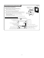
3. Exterior dimensions........................................................................ 1
4. Circuit board component layout .................................................... 1
5. System configuration ..................................................................... 2
6. Installation of interface kit.............................................................. 3
7. Wired remote control ...................................................................... 8
8. Insatallation of wired remote control ............................................ 9
9. Setting functions using the wired remote control ....................... 10
10. Super link adapter ........................................................................... 14
11. Operation permission/prohibition control .................................... 16
12. External control (remote display) /control of input signal .......... 17
INTERFACE KIT (OPTIONAL PARTS)
1. Applicable model
Name
Type
Interface kit
SC-BIKN-E
SRK50ZHX-S
SRK60ZHX-S
2. List of connectable devices
Name
Wired remote control
Super link adapter
Central control
Type
RC-E3
SC-ADN-E
SC-SL1N-E, SC-SL2N-E, SC-SL3N-AE/BE
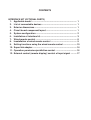
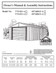
18.2
83.5
135
1300
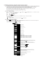
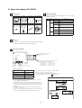
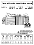
3. Exterior dimensions
34
120
4. Circuit board component layout
Indoor unit connection terminal
DIP switch (SW2)
DIP switch (SW3)
Address setting
rotary switch (SW1)
Wired remote control and Super link adapter terminal block
CNT terminal
-
1-
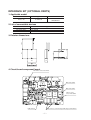
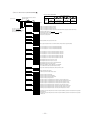
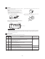
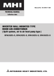
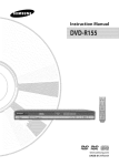
q Wired remote control system
SC-BIKN-E
RC-E3
Interface kit
Room air conditinoer
Wired remote control
w Control of multiple units with a remote control
Central
control
Super link
SC-ADN-E adapter
SC-ADN-E
Interface kit SC-BIKN-E
SC-ADN-E
SC-BIKN-E
SC-ADN-E
SC-BIKN-E
Control contents
Use
Using the wired remote control
system, users can run and stop the
unit, switch operations, adjust the
temperature, fan speed and air flow
direction (up or down), and control
timer operation .
Use a wired remote control for
retirement homes, school classrooms
and similar locations.
Multiple units (16units~48units)
can be cotrolled with a single
remote control.
Contact your dealer when you
connected 48 units or more.
For hotels and similar facilities
with multiple units installed, the
remote control is used to turn
multiple air conditioning units ON
or OFF.
Parts used
• Wired remote control
(RC-E3)
• Interface kit
(SC-BIKN-E)
• Interface kit
(SC-BIKN-E)
• Super link adapter
(SC-ADN-E)
• Central control
(SC-SL1N-E, SC-SL2N-E,
SC-SL3N-AE/BE)
SC-BIKN-E
Signal wire
(1.8m supplied)
-
Room
air conditinoer
RCE3
Wired remote control
RCE3
RCE3
• Wired remote control
(RC-E3)
RCE3
1
2Central
control
SC-ADN-E
SC-ADN-E
SC-ADN-E
SC-ADN-E
SC-ADN-E
Super link
adapter
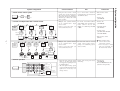
Multiple units (16units~48units)
can be cotrolled with a single
remote control.
Contact your dealer when you
connected 48 units or more.
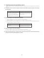
For users who want to exercise
central control together with a
package air conditioning system,
such as an office.
• Using the remote start/stop switch
timer, etc., the unit can be started
and stopped by inputting level or
by inputting pulses.
• The run signal, heating signal,
compressor ON signal and check
signal can be received by nonvoltage contacts.
Remote start and stop and remote
monitoring.
1 Either wireless remote
control or wired remote
control can be selected.
If it is necessary to control
each room separately, use
the wired remote control.
Interface kit SC-BIKN-E
Signal wire
(1.8m supplied)
Packaged
air conditioner
RCE3
Wired remote control
RCE3
RCE3
RCE3
Room
air conditinoer
RCE3
Wired remote control
e Remote operation
Common
XR1
XR1
XR2
SC-BIKN-E
XR3
Room air conditinoer
XR4
Operation output
XR2
Heating output
XR3
Compressor
operation output
XR4
Malfunction output
XR5
Interface kit
Remote
operation
input
XR5
Remote operation
AC 220~240V
Power supply
DC 12/24 V or
AC 220~240V
1
• Inrterface kit
(SC-BIKN-E)
• Remote ON/OFF monitor kit
(Customer arrangements)
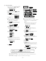
5. System configuration
System configuration
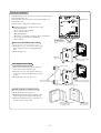
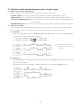
6. Installation of interface kit
Accessories included in package
Please check to make sure all the accessories have been included.
Part name
Quantity
Indoor unit connection cable (total cable length: 1.8 m)
1
Wood screws (for mounting the interface: ø4 × 25)
2
Tapping screws (for mounting the clamp and interface mounting bracket)
3
Interface mounting bracket
1
Clamp (for the indoor unit)
1
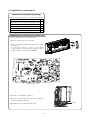
Connecting the interface and indoor unit
q Remove the air inlet panel, lid and front panel.
w
w Take the control lid out of the control box.
e There is a terminal (marked with CNS) for the indoor
control boad.
In connecting an interface, connect to the terminal
securely with the connection harness supplied with an
optional “Interface connection kit SC-BIKN-E”.
r
Connection terminal
r House the control lid in the control box.
t Fasten the connection harness onto the indoor control box
with clamp supplied with the kit.
Clamp
y Reinstall the front panel, lid and air inlet panel.
-
3-
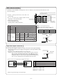
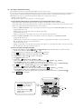
Connecting the interface and the indoor unit
Wiring inlet
(top or back)
7Remove the upper case of the interface.
9Fasten with the clamp
• Take out the 2 screws in the interface case.
8Install the indoor unit
connection cable
8Install the indoor unit’s connection cable in the interface.
• Connect the connector of the indoor unit connection cable to the
connector on the interface’s circuit board.
9Fasten the indoor unit connection cable using clamp.
• Cable can be brought in from the top or from the back.
• Use side cutters, etc. to cut out the thin knockouts used to run wires into the case.
0Connect the indoor unit’s connection cable to the control board in the indoor unit.
• Connect the indoor unit connection cables’ connector securely to the
indoor unit’s control board.
• Use the clamp provided as an accessory to fasten the connection cable,
fastening it securely to the control box.
• Read the installation manual for the indoor unit concerning connections inside the indoor unit.
7Remove
the upper
case
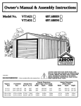
Names of each part of the interface unit
ROM terminal
Clamp for fastening indoor
unit connection cable
Interface board
DIP switch (SW2)
Indoor unit connection terminal
DIP switch (SW3)
Wired remote control*
terminal block
Address setting rotary switch (SW1)
CNT terminal
Super link adapter (SC-ADN-E) terminal block*
Clamp for fastening the super link adapter *
(SC-ADN-E) connection cable
Clamp for fastening the wired*
remote control connection cable
* Either the super link adapter (SC-ADN-E) cable or the wired remote control connection cable can be connected.
-
4-
Interface installation
Install the interface so that the connection cable can reach the indoor
unit (approximately 1.3 m).
If the connection cable is extended, operation will be faulty, so do
not extend the cable.
Fasten the unit to a wall, pillar or similar location.
DO NOT install interface and wired remote control
on the following places
KPlaces exposed to direct sunlight
KPlaces near heat devices
KHigh humidity places
KHot surface or cold surface enough to generate condensation
KPlaces exposed to oil mist or steam directly
KUneven surface
If the unit is mounted directly to a wall
Wiring inlet
Use a side cutter or
similar tool to open
the thin knockouts in
the case for running
wires.
Wiring inlet
1Mount the lower case of the interface unit to a flat
surface using the wood screws supplied with the
unit.
2Mount the upper case.
2 Mount the
upper case
1 Fasten it to a wall or pillar
(2 wood screws)
Recessing the unit in a wall
Connection cable
1Recess the electrical box (procured locally) and
each connection cable inside the wall.
2Fasten the lower case of the interface unit to the
electrical box using screws (M4 screws, procured
locally).
3Mount the upper case to the lower case.
1Recess the electrical
box and connection cables
2Fasten it to the electrical box.
2 M4 screws (procured locally)
Electrical box
(procured locally)
3Mount the upper case
Mounting with the mounting bracket
1Mount the interface unit’s upper case.
2Mount the mounting bracket to the interface unit
using the tapping screws supplied with the unit.
3Mount the mounting bracket to a wall surface, etc.
using the wood screws provided.
2Mount the mounting bracket
on the interface unit.
(3 tapping screws)
-
5-
3Mount the bracket
on a wall or pillar
(2 wood screws)
CNT connector functions
Turning the contacts ON/OFF, the running status of the air conditioner can be monitored from the External control
unit (remote display).
0.3 mm2 (Keep the distance between the relay and the
CNT terminal within 2 m.)
1Connect a locally procured remote control unit to the
CNT terminal.
1
2
3
4
5
6
2In case of the pulse input, switching “OFF” the DIP
switch SW2-1 on the main unit PCB.
CNT connector
3When setting at Operation
permission/prohibition Mode,
switching “OFF” the DIP switch SW2-3.
Input
Output
Common
XR1
ON output (XR1 = ON) during air conditioner operation
Output 2 Heating output
ON output (XR2 = ON) during heating operation
Compressor
Output 3 operation output
XR4
XR5
XR5
| Output 2
AC 220~240V
| Output 3
| Output 4
{ Input
Power supply
DC 12/24 V or
AC 220~240V
XR1~4 are for the DC 12V relay
XR5 is a DC 12/24 or AC 220~240V relay
CNT connector (local) maker, model
Connector
Terminals
Output 4 Malfunction output ON output (XR4 = ON) during an abnormal stop
Input Remote
control input
XR3
XR4
ON output (XR3 = ON) during compressor operation
Level input External control
(At shipment) (At shipment)
Level input Operation permission/
(At shipment) prohibition (SW2-3: OFF)
XR2
XR3
Content
Output 1 Operation output
XR1
XR2
| Output 1
XR5 OFF
XR5 ON
ON Air conditioner ON
OFF Air conditioner OFF
XR5 OFF
XR5 ON
ON Air conditioner OFF
OFF Air conditioner OFF
Molex
Molex
5264-06
5263T
DIP switch
(SW2-3)
Pulse input External control XR5 Air conditioner ON/OFF is inverted
(SW2-1: OFF) (At shipment)
depending on the pulse signal at OFF ON.
Pulse input Operation permission/ XR5 Air conditioner ON depending
(SW2-1: OFF) prohibition (SW2-3: OFF)
on the level signal at OFF ON.
DIP switch
(SW2-1)
In the operation permission/prohibited mode, wired/wireless remote control operations are
allowed only when the input is turned ON.
Super link adapter connection
See the super link adapter’s manual concerning connections to the super link adapter.
For electrical work, the power supply of all appliance on the super link line must
be turned off.
1Switching “ON” the DIP switch SW2-2 on the circuit board.
Caution: You can use the wireless remote control, which is attached to the indoor
unit, even after connecting the wired remote control. However, some of
functions other than the basic functions such as the RUN/STOP, setting
temperature change, etc. may not operate properly. On some functions, it
may occur also a mismatch between the display and actual actions.
DIP switch
(SW2-2)
2Connections between the interface and super link adapter
Interface side
Super link adapter
terminal block
Y
X
Y
X
No.
1
2
3
4
Super link
adapter
Names of recommended signal wires
Shielded wire
Vinyl cabtyre round cord
Vinyl cabtyre round cable
Vinyl insulated wirevinyl sheathed cable for control
Within 200 m
Within 300 m
Within 400 m
Within 600 m
3Fasten the super link adapter cable with clamps.
-
6-
0.5 mm2 × 2 cores
0.75 mm2 × 2 cores
1.25 mm2 × 2 cores
2.0 mm2 × 2 cores
Wired remote control connection
Please see the instruction in the wired remote control's manual concerning connection to the wired remote control.
1Set to ON the DIP switch “SW2-2” on the PCB.
DIP suitch
(SW2-2)
Caution: You can use the wireless remote control, which is attached to the indoor unit, even after connecting the wired remote control.
However, some of functions other than the basic functions such as the RUN/STOP, setting temperature change, etc. may not operate
properly. On some functions, it may occur also a mismatch between the display and actual actions.
2Connect the interface and remote control.
Installation and wiring of remote control
AInstall remote control referring to the attached installation manual.
BWiring of remote control should use 0.3mm2 x2 core wires or cables. (on-site configuration).
CMaximum prolongation of remote control wiring is 600 m.
If the prolongation is over 100m, change to the size below.
But, wiring in the remote control case should be under 0.5mm2. Change the wire size outside of the case according to wire connecting.
Waterproof treatmnet is necessary at the wire connecting section. Be careful about contact failure.
100-200m......0.5mm2x2 cores, Under 300m......0.75mm2x2 cores, Under 400m......1.25mm2x2 cores, Under 600m......2.0mm2x2 cores.
DAvoid using multi-core cables to prevent malfunction.
EKeep remote control line away from earth (frame or any metal of building).
FMake sure to connect remote control line to the remote control and terminal block of interface kit (No polarity)
3Fasten the connection cables with clamps.
Control of multiple units by a single remote control.
A remote control can control multiple units (Up to 16).
Rotary
switch
In above setting, all multiple units will operate under same mode and temperature setting.
1Connect all interface kits with 2 core remote control line.
2Set unique remote control communication address from "0" to "F" to each
Interface kit(1) Interface kit(2) Interface kit(16)
inside unit by the rotary switch SW1 on the interface kit's PCB.
Adress"1"
Adress"0"
Adress"F"
3After a unit is energized, it is possible to display an indoor unit address by
pressing AIR CON NO. button on the remote control unit. Press the
Remote control line (no polarity)
or button to make sure that all indoor units connected are displayed in
Remote control
order.
Master/ slave setting when more than one remote control unit are used
A maximum of two remote control units can be connected to one indoor unit (or
one group of indoor units.)
1Set SW1 (wired remote control) to "Slave" for the slave remote control unit.
It was factory set to "Master" for shipment.
K Caution: Remote control sensor is disabled.
Interface kit
Switch
setting
contents
Wired remote
control: SW1
M
S
Master
remote control
Slave
remote control
Remote control line
(no polarity)
Remote
control
"Master"
Remote
control
"Slave"
When using the wired remote control in parallel with the wireless remote control:
It is necessary to change the setting temperature range for the wired remote control. (The setting temperature may not be displayed correctly
unless it is changed.) Change the setting temperature for the wired remote control with the following procedure.
How to set upper and lower limit value
1. Stop the air-conditioner, and press
(SET) and
three seconds.
The indication changes to"FUNCTION SET "
(MODE) button at the same time for over
2.
3.
4.
5.
6.
Press
button once, and change to the "TEMP RANGE " indication.
Press
(SET) button, and enter the temperature range setting mode.
Confirm that the "Upper limit
" is shown on the display.
Press
(SET)button to fix.
1Indication: "
SET UP" "UPPER 28˚C
"
2Select the upper limit value 30˚C with temperature setting button ."UPPER30˚C "
(blinking)
3Press
(SET) button to fix. "UPPER 30˚C" (Displayed for two seconds)
After the fixed upper limit value displayed for two seconds, the indication will retum
to"UPPER LIMIT ".
7. Press
button once, "LOWER LIMIT
" is selected, press
(SET) button to fix.
1Indication: "
SET UP"
"LOWER 20˚C
"
2Select the lower limit value 18˚C with temperature setting button ."LOWER18˚C "
(blinking)
3Press
(SET) button to fix. "LOWER 18˚C" (Displayed for two seconds)
After the fixed lower limit value displayed for two seconds, the indication will retum
to"LOWER LIMIT "
8. Press ON/OFF button to finish.
-
7-
6-w
7-w
TEMP RANGE
TEMP
ON/OFF
8
3 • 5 • 6-e
7-e
TIEMR
SET
FAN SPEED
MODE
GRILL
RESET
LOUVER
VENTI
AIR CON NO.
CHECK
2
• It
1
TEST
Previous button
is possible to finish by pressing
ON/OFF button on the way, but
unfinished change of setting is
unavailable.
• During
setting, if you press
(RESET) button, you return to the
previous screen.
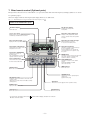
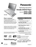
7. Wired remote control (Optional parts)
The figure below shows the remote control with the cover opened. Note that all the items in the liquid crystal display (LCD) area are shown
for explanation purpose.
Characters displayed with dots in the liquid crystal display (LCD) area are abbreviated.
Note (1) The SRK models do not support the buttons and functions displayed in
.
Pull the cover downwards to open.
Weekly timer display
Ventilation display
Displays the settings of the
weekly timer.
Cannot be used.
Central control display
Displayed when the air conditioning system is
controlled by centralized remote control.
Operation setting display area
Displays setting temperature, airflow
volume, operation mode and operation
message.
Timer operation display
Operation/check indicator light
Displays the timer operation setting.
During operation: Lit in green
In case of error: Flashing in red
Operation/stop button
Temperature setting buttons
This button is used to operate and stop
the air conditioning system.
Press the button once to operate the
system and press it once again to stop
the system.
These buttons are used to set the
temperature of the room.
Timer button
This button is used to set
the timer mode.
(The comfortable timer or sleep
operation cannot be selected.)
MODE button
This button is used to change the operation mode.
(The clean operation or allergen clear
operation cannot be selected.)
Timer setting buttons
FAN SPEED button
These buttons are used to set
the timer mode and the time.
This button is used to set the airflow
volume.
(AUTO, HI POWER or ECONO
cannot be selected)
VENT button
GRILL button
Cannot be used.
Cannot be used.
LOUVER button
This button is used to operate/stop the
swing louver.
(Up/down swing only)
AIR CON No. button
•Display the indoor unit number connected to this
remote control.
•This button is used for indoor unit address setting.
(”00” appears.)
SET button
This button is used to apply the timer operation setting.
CHECK button
Display the data of the control.
TEST button
RESET button
Cannot be used.
* If you press any of the buttons above and “
But it does not mean a failure.
Cannot be used.
INVALID OPER” is display, the button has no function.
-
8-
-
9-
9. Setting functions using the wired remote control
(1) The initial function setting for typical using is performed automatically for a remote control unit and an
indoor unit by the outdoor unit connected, when remote control and inside unit are connected.
As long as they are used in a typical manner, there wiil be no need to change the initial settings.
If you would like to change the initial setting marked “ ”, set your desired setting as for the selected item.
The procedure of functional setting is shown as the following diagram.
As for detail of setting, refer to the installation manual of remote control.
(2) Flow of function setting
Start
: While indoor unit do not operate, press “
” (SET) and “
” (MODE) button for 3 seconds at the same time.
” (SET) button.
Finalizea
: Press “
” (RESET) button.
Reset : Press “
button.
Select : Press
button.
End
: Press
It is possible to finish above setting on the way, and unfinished change of setting is unavailable.
“ ” : Initial settings
“ ” : Automatic criterion
“ ” : The SRK model cannot set the items described in in the function.
(3) Clearing the function setting
Pressing
(CHECK) +
(TIMER) +
(MODE) buttons simultaneously reverts the function setting data to
the data which are set at the shipping from factory.
1 Remote control unit functions ( FUNCTION )
01
(Remote control function)
Function
setting
When you use at 50Hz area
When you use at 60Hz area
02
Automatic operation is impossible
03
Temperature setting button is not working
04
Mode button is not working
05
On/Off button is not working
06
Fan speed button is not working
07
Louver button is not working
08
Timer button is not working
09
Remote thermistor is not working.
Remote thermistor is working.
Remote thermistor is working, and to be set for producing +3.0°C increase in temperature.
Remote thermistor is working, and to be set for producing +2.0°C increase in temperature.
Remote thermistor is working, and to be set for producing +1.0°C increase in temperature.
Remote thermistor is working, and to be set for producing -1.0°C increase in temperature.
Remote thermistor is working, and to be set for producing -2.0°C increase in temperature.
Remote thermistor is working, and to be set for producing -3.0°C increase in temperature.
10
11
In case of Single split series, by connecting ventilation device to CNT of the indoor printed circuit board, the operation of
ventilation device is linked with the operation of indoor unit.
In case of Single split series, by connecting ventilation device to CNT of the indoor printed circuit board, you can operate/
stop the ventilation device independently by
(VENT) button.
12
If you change the range of set temperature, the indication of set temperature will vary following the control.
If you change the range of set temperature, the indication of set temperature will not vary following the control, and
keep the set temperature.
13
Airflow of fan becomes the three speed of
Airflow of fan becomes the two speed of
Airflow of fan becomes the two speed of
Airflow of fan is fixed at one speed.
14
-
If you change the remote control function "14
you must change the indoor function "04
You can select the louver stop position in the four.
The louver can stop at any position.
-
.
.
.
",
" accordingly.
15
16
If you input signal into CNT of the indoor printed circuit board from external, the indoor unit will be operated
independently according to the input from external.
If you input into CNT of the indoor printed circuit board from external, all units which connect to the same remote
control are operated according to the input from external.
17
In normal working indication, indoor unit temperature is indicated instead of airflow.
(Only the master remote control can be indicated. )
18
Heating preparation indication should not be indicated.
19
Temperature indication is by degree C
Temperature indication is by degree F
-
10 -
2 Indoor unit functions (I/U FUNCTION
)
Note1: Fan setting of "HIGH SPEED"
Indoor unit air flow setting
Fan tap
(Indoor unit function)
Only when plural indoor units are connected
Indoor No. selection
Function
(Note3)
setting
02
FAN
SPEED
SET
(Note1)
STANDARD
HI-MID-LO
HI-LO
HI- MID
HIGH
SPEED1 2
UHI - HI- MID
UHI - MID
UHI- HI
Initial function setting of some indoor unit is "HIGH SPEED".
03
If to change re-set with other indoor
unit, push AIRCON NO.
button, and indoor selection indication
(for example: I/U 000) is set back.
The filter sign is indicated after running for 180 hours.
The filter sign is indicated after running for 600 hours.
The filter sign is indicated after running for 1000 hours.
The filter sign is indicated after running for 1000 hours, then the indoor unit will be stopped by compulsion after 24 hours.
04
If you change the indoor function "04
",
you must change the remote control function "14
You can select the louver stop position in the four.
The louver can stop at any position.
" accordingly.
05
06
Permission/prohibition control of operation will be valid.
07
When stop signal is inputed from remote on-off terminal "CNT-6", all indoor units are stopped immediately.
08
To be reset for producing +3.0°C increase in temperature during heating.
To be reset for producing +2.0°C increase in temperature during heating.
To be reset for producing +1.0°C increase in temperature during heating.
09
To be reset producing +2.0°C increase in return air temperature of indoor unit.
To be reset producing +1.5°C increase in return air temperature of indoor unit.
To be reset producing +1.0°C increase in return air temperature of indoor unit.
10
To be reset producing -1.0°C increase in return air temperature of indoor unit.
To be reset producing -1.5°C increase in return air temperature of indoor unit.
To be reset producing -2.0°C increase in return air temperature of indoor unit.
When heating thermostat is OFF, fan speed is low speed.
When heating thermostat is OFF, fan speed is set speed.
When heating thermostat is OFF, fan speed is operated intermittently.
When heating thermostat is OFF, the fan is stopped.
When the remote thermistor is working, "FAN OFF" is set automatically.
Do not set "FAN OFF" when the indoor unit's thermistor is working.
11
Change of indoor heat exchanger temperature to start frost prevention control.
12
Working only with the single split series.
To control frost prevention, the indoor fan tap is raised.
13
Drain pump is run during cooling and dry.
Drain pump is run during cooling, dry and heating.
Drain pump is run during cooling, dry, heating and fan.
Drain pump is run during cooling, dry and fan.
14
After cooling is stopped or cooling thermostat is OFF, the fan does not perform extra operation.
After cooling is stopped or cooling thermostat is OFF, the fan perform extra operation for half an hour.
After cooling is stopped or cooling thermostat is OFF, the fan perform extra operation for an hour.
After cooling is stopped or cooling thermostat is OFF, the fan perform extra operation for six hours.
15
After heating is stopped or heating thermostat is OFF, the fan does not perform extra operation.
After heating is stopped or heating thermostat is OFF, the fan perform extra operation for half an hour.
After heating is stopped or heating thermostat is OFF, the fan perform extra operation for two hours.
After heating is stopped or heating thermostat is OFF, he fan perform extra operation for six hours.
16
During heating is stopped or heating thermostat is OFF, the fan perform intermittent operation for five minutes with low fan speed after
twenty minutes' OFF.
During heating is stopped or heating thermostat is OFF, the fan perform intermittent operation for five minutes with low fan speed after
five minutes' OFF.
-
11 -
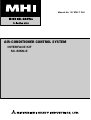
(4) How to set function
Operation message
Function description:
setting description:
1) Stop air-conditioner and press
(SET)
(MODE)
buttons at the same time for over three seconds, and the
"FUNCTION SET
" will be displayed.
,
Function No.
Fixing button
2) Press
(SET) button.
3) Make sure which do you want to set, " FUNCTION "
(remote control function) or "I/U FUNCTION " (indoor
unit function).
4) Press
or
button.
Selecct " FUNCTION " (remote control function) or
"I/U FUNCTION " (indoor unit function).
6)
Finishing button
2)
Starting button
1)
6)-8
5) Press
7)
Indoor unit selection button
Previous screen button
(SET) button.
On the occasion of indoor unit function selection
On the occasion of remote control function selection
"DATA LOADING" (Indication with blinking)
"DATA LOADING" (Blinking for 2 to 23 seconds to read the data)
Display is changed to "01 GRILLE
Indication is changed to "01 AUTO FILTER CLEANING".
Go to .
SET".
Press
or
button.
"No. and function"are indicated by turns on the remote
control function table, then you can select from them.
(For example)
[Note]
(1) If plural indoor units are connected to a remote control,
the indication is "I/U 000" (blinking)
The lowest
number of the indoor unit connected is indicated.
Function No.
Function
Press
(SET) button.
The current setting of selected function is indicated.
(for example) "AUTO RUN ON"
If "02 AUTO
RUN SET" is selected
(2) Press
or
button.
Select the number of the indoor unit you are to set
If you select "ALL UNIT ", you can set the same
setting with all unites.
(3) Press
(SET) button.
Setting
Press
or
button.
"No. and function" are indicated by turns on the indoor unit
function table, then you can select from them.
(For example)
Press
or
button.
Select the setting.
Function No.
Function
Press
(SET) button.
The current setting of selected function is indicated.
(For example) "STANDARD"
If "02 FAN SPEED SET"
is selected.
Press
(SET)
"SET COMPLETE" will be indicated, and the setting
will be completed.
Then after "No. and function" indication returns, Set as
the same procedure if you want to set continuously ,and
if to finish, go to 7.
Setting
Press
or
button.
Select the setting.
Press
(SET) button.
"SET COMPLETE" will be indicated, and the setting will be
completed.
Then after "No. and function" indication returns, set as the same
procedure if you want to set continuously , and if to finish, go to 7).
7) Press ON/OFF button.
Setting is finished.
When plural indoor units are connected to a remote control,
press the AIRCON NO. button, which allows you to go back
to the indoor unit selection screen. (example "I/U 000 ")
It is possible to finish by pressing ON/OFF button on the way, but unfinished change of setting is
unavailable.
During setting, if you press
(RESET) button, you return to the previous screen.
Setting is memorized in the control and it is saved independently of power failure.
How to check the current setting
When you select from "No. and funcion" and press set button by the previous operation, the "Setting" displayed first is
the current setting.
(But, if you select "ALL UNIT
", the setting of the lowest number indoor unit is displayed.)
-
12 -
(5) The range of temperature setting.
When using the wired remote control in parallel with the wireless remote control:
It is necessary to change the setting temperature range for the wired remote control. (The setting temperature may not be displayed
correctly unless it is changed.) Change the setting temperature for the wired remote control with the following procedure 2).
When shipped, the range of set temperature differs depending on the operation mode as below.
Heating : 16~30°C (55~86°F)
Except heating (cooling, fan, dry, automatic) : 18~30°C (62~86°F)
1) Upper limit and lower limit of set temperature can be changed with remote control.
Upper limit setting: valid during heating operation. Possible to set in the range of 20 to 30°C (68 to 86°F).
Lower limit setting: valid except heating (automatic, cooling, fan, dry) Possible to set in the range of 18 to 26°C (62 to 79°F).
When you set upper and lower limit by this function, control as below.
a) When !2 TEMP RANGE SET, remote control function of function setting mode is "INDN CHANGE" (factory setting),
[If upper limit value is set]
During heating, you cannot set the value exceeding the upper limit.
[If lower limit value is set]
During operation mode except heating, you cannot set the value below the lower limit.
b) When !2 TEMP RANGE SET, remote control function of function setting mode is "NO INDN CHANGE"
[If upper limit value is set]
During heating, even if the value exceeding the upper limit is set, upper limit value will be sent to the indoor unit.
But, the indication is the same as the temperature set.
[If lower limit value is set]
During except heating, even if the value lower than the lower limit is set, lower limit value will be sent to the indoor unit.
But, the indication is the same as the temperature set.
2) How to set upper and lower limit value
a) Stop the air-conditioner, and press
(SET) and
The indication changes to "FUNCTION SET "
(MODE) button at the same time for over three seconds.
b)
c)
d)
e)
f)
Press
button once, and change to the "TEMP RANGE " indication.
Press
(SET) button, and enter the temperature range setting mode.
Confirm that the "Upper limit " is shown on the display.
Press
(SET)button to fix.
1Indication: "
SET UP" "UPPER 28˚C
"
2Select the upper limit value 30˚C with temperature setting button . "UPPER30˚C " (blinking)
3Press
(SET) button to fix. "UPPER 30˚C" (Displayed for two seconds)
After the fixed upper limit value displayed for two seconds, the indication will retum to "UPPER LIMIT ".
g) Press button once, "LOWER LIMIT " is selected, press
(SET) button to fix.
1Indication: "
SET UP" "LOWER 20˚C
"
2Select the lower limit value 18˚C with temperature setting button . "LOWER18˚C " (blinking)
3Press
(SET) button to fix. "LOWER 18˚C" (Displayed for two seconds)
After the fixed lower limit value displayed for two seconds, the indication will retum to "LOWER LIMIT "
h) Press ON/OFF button to finish.
It is possible to finish by pressing
ON/OFF button on the way, but
unfinished change of setting is
unavailable.
f)g)h)
c) e) f)
g)
During setting, if you press
(RESET) button, you return to the
previous screen.
a)
b)
-
13 -
Previous button
10. Super link adapter (SC-ADN-E)
1 Accessories
3 Control switching
SL E board
Metal box
Metal cover
Screw for Ground
Settings can be changed by the switch SW3 on the SL E board
as in the following.
M4×8L 2 pieces
Switch
Symbol
Switch
Remarks
ON
Master
1
Pan head screws Locking supports
Grommet
Binding band
2
To secure the
print board and
the metal box
Made of nylon
4 pieces
4×8L 2 pieces
SW 3
3
OFF (default)
Slave
ON
Fixed previous protocol
OFF (default)
Automatic adjustment of Super Link
protocol
ON
Indicates the forced operation stop
when abnormality has occurred.
OFF (default)
Indicates the status of running/stop as it is,
when abnormality has occurred.
ON
The hundredth address activated “1”
OFF (default)
The hundredth address activated “0”
4
2 Function
Allowing the central control SL1N-E, SL2N-E, and SL3N-AE/BE
to control and monitor the room air conditioning unit.
4 Connection Outline
Blue
A
A
Blue
Run
Abnormal
SL E board
B
B
Black
LED3
LED2
X
SW3
Master/Slave
address
X
White
Y
Y
ON
OFF
Connected to the terminals for
Super Link signal lines
SW1
SW2
Network address setting switches
[000]-(127)
Connected to the interface kit terminals (no polarity)
(the length should be 600 m or shorter)
200 m or shorter ...........0.5 mm2 × 2 cores
300 m or shorter ...........0.75 mm2 × 2 cores
400 m or shorter ...........1.25 mm2 × 2 cores
600 m or shorter ...........2.0 mm2 × 2 cores
Signal line specification
Communication method
Line type
New Super Link
(*1) Up to 1500 m for 0.75 mm2, and up to 1000 m for 1.25mm2.
Do not use 2.0 mm2. It may cause an error.
MVVS
2
Line diameter
0.75/1.25mm
Signal line (total length)
up to 1500/1000m (*1)
Signal line (maximum length)
up to 1000m
(*2) Connect grounding on both ends of the shielding wire. For the
grounding method, refer to the section “
5
Installation”.
Basic Connections
(1) Set the Super Link network address with SW1 (tens place), SW2 (ones
place), and SW3-4 (hundreds place).
(2) Set the SL E board SW3-1 to be ON (Master) when using this without
any remote control (no wired remote control nor wireless remote control).
(3) Set up the plural master/slave device using the dip switches on the indoor
unit board.
(4) Set up the remote control master/slave device using the slide switch on
the remote control board.
(5) Set up "0" to "F" using the address rotary switch on the indoor unit board
when controlling the indoor unit with the multiple remote control.
Outdoor unit 1 2 3
Internal/external Crossing
Indoor unit
Interface kit (SC-BIKN-E)
X Y
X Y
Super link adapter
(SC-ADN-E)
A B
X Y
Network A B
options
-
14 -
1 2 3
Wired remote control
(RC-E3)
X Y
5 Installation
1. When using the metal box (mounted on the indoor unit / mounted
on the back of the remote control):
(1) Mount the SL E board in the metal box using the locking
supports.
(2) Wiring should go through the provided grommet since then
through the wiring to the hole on the Metal box.
Secure the grommet after inserting the grommet into the
Metal box as shown in below figure, then tie the wiring at the
outlet of the unit using a binding band.
When installed outside the indoor unit, put the metal cover on.
When installed on the back of the remote control, mount it
directly on the remote control bottom case.
SL E board
Binding band
Locking supports (4)
Connect grounding. Connect grounding for the power line to
Ground 1, and grounding for the signal line to Ground 2 or
to the Ground on the indoor unit control box.
Ground
Ground
Screw for Ground (2)
Location of installation
Install the device at the location where there are no electromagnetic waves nor where there is water and dust. The specified
temperature range of the device is 0 to 40˚C. Install the device at the location where the ambient temperature stays within the
range. If it exceeds the specification, make sure to provide solution such as installing a cooling fan. When used outside of the
range, it may cause abnormal operation.
6 Indicator display
Check the LED 3 (green) and LED 2 (red) on the SL E board for flashing.
SL E board LEDs
Red
Green
Off
Flashing
Inspection mode
Display on the integrated
network control device
Normal communication
• Disconnection in the remote control communication line (X or Y)
• Short-circuit in the remote control communication line (between X and Y)
• Faulty indoor unit remote control power
• Faulty remote control communication circuit
• Faulty CPU on SL E board
No corresponding unit
number
Off
Off
One flash
Flashing
• Disconnection in the Super Link signal line (A or B)
• Short-circuit in the Super Link signal line (between A and B)
• Faulty Super Link signal circuit
Two
flashes
Flashing
• Faulty address setting for the SL E board
(Set up the address for more than 128)
Three
flashes
Flashing
• SL E board parent not set up when used without a remote control
• Faulty remote control communication circuit
E1
Four
flashes
Flashing
• Address overlapping for the SL E board and the Super Link network connected indoor unit
E2
Off
Flashing
• Number of connected devices exceeds the specification for the multiple indoor unit control
E10
-
15 -
11. Operation permission/prohibition control
The air conditioner operation is controlled by DIP switch SW2-3 on the interface kit board and inputting the external signal into
the CnT.
(1) The operation mode is switched over between Permission and Prohibition by DIP switch SW2-3 on the interface
kit control board.
When the DIP switch SW2-3 is ON
When the DIP switch SW2-3 is OFF
Normal operation is enable (when shipping)
Permission / Prohibition mode
When CnT input is set to ON, the operation starts and
When CnT input is set to ON, the operation mode is
if the input is set to OFF, the operation stops.
changed to permission and if input is set to OFF the
For the CnT and remote control inputs, the input which
operation is prohibited.
is activated later has priority and can start and stop the
operation.
(2) When the CnT input is set to ON (Operation permission)
(a)
The air conditioner can be operated or stopped by the remote control signal.
(When the "CENTER" mode is set, the operation can be controlled only by the center input.)
(b)
When the CnT input is changed from OFF to ON, the air conditioner operation mode is changed depending on the status of
the DIP switch SW2-1 on the interface kit board.
When the DIP switch SW2-1 is ON
When the DIP switch SW2-1 is OFF
The signal (a) above starts the air conditioner.
When the CnT input is set to ON, the air conditioner
(Shipping status)
starts operation. After that, the operation of the air
conditioner depends on (a) above. (Local status)
(3) When the CnT input is set to OFF (Prohibition)
(a)
The air conditioner cannot be operated or stopped by the remote control signal.
(b)
The air conditioner operation is stopped when the CnT input is changed from ON to OFF.
(4) When the operation permission / prohibition mode is set to effective by the indoor function setting selected by
the remote control, the operation depends on (1) above.
-
16 -
12. External control (remote display)/control of input signal
(1) External control (remote display) output
Following output connectors (CnT) are provided on the printed circuit board of interface kit.
• Operation output: Power to engage DC 12V relay (provided by the customer) is outputted during operation.
• Heating output: Power to engage DC 12V relay (provided by the customer) is outputted during the heating operation.
• Compressor OPERATION output: Power to engage DC 12V relay (provided by the customer) is outputted while the compressor is operating.
• MALFUNCTION output: When any error occurs, the power to engage DC 12V relay (provided by the customer) is outputted.
(2) Control of input signal
Control of input signal (switch input, timer input) connectors (CnT) are provided on the control circuit board of interface kit.
However, when the operation of air conditioner is under the Center Mode, the remote control by CnT is invalid.
(a) Level input
If the factory settings (DIP switch SW2-1 EXTERNAL INPUT on the PCB of interface kit) are set, or “LEVEL INPUT” is
selected in the wired remote control’s indoor unit settings.
1)
Input signal to CnT OFF → ON
Air conditioner ON
2)
Input signal to CnT ON → OFF
Air conditioner OFF
ON
ON
CnT Input
OFF
OFF
Unit
(CASE B)
*ON
*ON
ON
ON
Unit
(CASE A)
OFF
OFF
OFF
OFF
Note (1) The ON with the * mark indicates an
ON operation using the remote control
unit switch, etc.
ON
ON
OFF
OFF
(b) Pulse input
When DIP switch SW2-1 on the PCB of interface kit is OFF at the field or “PULSE INPUT” is selected in the wired remote
control’s indoor unit settings.
Input signal to CnT becomes valid at OFF → ON only and the motion of air conditioner [ON/OFF] is inverted.
ON
CnT Input
OFF
Unit
(CASE A)
OFF
ON
OFF
OFF
ON
OFF
ON
Unit
(CASE B)
ON
OFF
-
17 -
AIR-CONDITIONER CONTROL SYSTEM
Air-Conditioning & Refrigeration Systems Headquarters
16-5, 2-chome, Kounan, Minato-ku, Tokyo, 108-8215, Japan
Fax : (03) 6716-5926
-
2-
No.116(1.1A) R