1
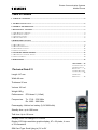
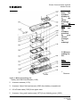
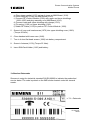
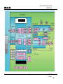
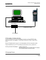
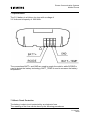
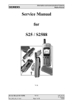
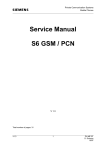
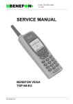
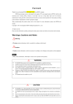
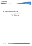
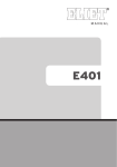
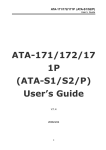
Private Communication Systems
Mobile Phones
Service Manual
S11(E)
V 1.1
Total number of pages: 18
V1.1
1
PN MP ST
D. Schnoor
04/98
Private Communication Systems
Mobile Phones
1Table of Contents
1 TABLE OF CONTENTS....................................................................................................................................2
1 TECHNICAL DATA S11....................................................................................................................................2
2 GENERAL INFORMATION.............................................................................................................................3
3 MECHANICAL CONCEPT...............................................................................................................................3
3.1 S11 MECHANICAL DRAWING ...........................................................................................................................4
3.2 DISASSEMBLING THE S11 ................................................................................................................................6
3.3 ASSEMBLING THE S11.....................................................................................................................................7
3.4 HANDSET DATECODES.....................................................................................................................................8
4 HARDWARE CONCEPT
...................................................................................................................................................................................9
4.1 BLOCK DIAGRAM............................................................................................................................................9
4.2 HARDWARE DESCRIPTION...............................................................................................................................11
4.3 POWER SUPPLY CONCEPT...............................................................................................................................12
4.4 CRITICAL CONDITIONS ..................................................................................................................................13
5 SOFTWARE PROGRAMMING.....................................................................................................................13
5.1 DESCRIPTION OF SOFTWARE BOOTING................................................................................................................14
5.2 LANGUAGE GROUPS......................................................................................................................................14
6 DEBLOCKING .................................................................................................................................................15
7 BATTERY.....16
7.1 SPECIFICATION.17
7.2 SHORT CIRCUIT
PROTECTION.........17
7.3 DEEP DISCHARGE
..........................18
7.4 BATTERY
DATECODES..........18
1Technical Data S11
Length 147 mm
Width 46 mm
Thickness 25 mm
Volume 160 cm³
Weight 185 g
Performance:
PCN class 2 (1 Watt)
Frequencies:
Tx: 1710 - 1785 MHz
Rx: 1805 - 1880 MHz
Powersupply: Lithium Ion battery (3,6V/1800mAh)
Standby time: up to 100 hours
Talk time: Up to 10 hours.
V1.1
Carging
Time: Full charge in 2.5 hours
2
Display LCD high-resolution graphic display, 97 x 33 pixels, 4 rows
of 16 characters
SIM Card Type: Small (plug in) 3V or 5V
PN MP ST
D. Schnoor
04/98
Private Communication Systems
Mobile Phones
2General Information
After the S6 PCN and the S6 Power PCN, the S11 is the third model of the new
handset generation for GSM-1800 in 3 Volt technology. Mechanically and technically
it is very similar to the S10.
In addition to the normal S11 another version called S11 E is available which offers
Enhanced Fullrate speech coding to improve the speech quality.
3Mechanical Concept
Note: All part numbers refer to mechanical drawing in section 4.1!
The S11 consists of two boards, the RF & Control module (1000) and the user
interface (1010).
The connection between those two boards is made by a normal connector with plugin contacts.
The RF connection from the display module to the RF & Control module is made by
an RF cable (1150) which is soldered onto to RF & Control module, which is covered
by two shieldings (1060, 1050).
The antenna (1130) is directly screwed into the lower case shell.
V1.1
3
PN MP ST
D. Schnoor
04/98
Private Communication Systems
Mobile Phones
The keypad (1020), the loudspeaker (1120), the microphone (1110), the dust
protection frame (1190) and the microphone gasket (1220) are mounted into the
upper case shell (1030). Make sure that the microphone contacts are properly bent
up when mounting.
When turning in the screws (1070, 1080) make sure that the right torque is used (25
Ncm), because this will have an effect on the funtionality of the handset.
The only removable part on the user interface is the ringer gasket (1170) which is
needed to increase the ringer volume.
3.1S11 Mechanical Drawing
V1.1
4
PN MP ST
D. Schnoor
04/98
Private Communication Systems
Mobile Phones
V1.1
5
PN MP ST
D. Schnoor
04/98
Private Communication Systems
Mobile Phones
Note: The
numbers
displayed
in
the
above
drawings
are
NO
ORDERING
Nos,
use
the
numbers
provided
by
your
service
manager
for
ordering!
3.2Disasse
mbling the
S11
ESD
regulations
have to be
followed!
1.
Remove
Figure 1: Mechanical Drawing S11
battery and SIM-Card-Reader (1160).
2. Unscrew antenna (1130).
3. Unscrew 4 short flat head screws (1080) from battery compartment.
4. Lift off lower case (1040) from upper case.
5. Unscrew 4 long oval head screws (1070) from shielding cover (1060).
V1.1
6
PN MP ST
D. Schnoor
04/98
Private Communication Systems
Mobile Phones
6. Lift off assembly of MMI-Board (1010) and RF-/Control Module (1000).
7. Level-2 repairs only:
a) Desolder RF-Cable (1150) from RF-/Control Module (1000).
b) Remove fixing spring (1100) from shielding cover (1060).
c) Remove RF-/Control Module (1000) along with upper and lower shielding
covers (1060+1050) from MMI-Board (1010).
e) Remove clamps (1210)
d) Separate shielding covers from RF-/Control Module and remove battery
contacts (1140).
e) Remove fixing pin (1090) from MMI-Board (1010).
f) Remove ringer gasket (1170) from MMI-Board (1010).
8. Remove dust protection frame (1190) from upper case (1030).
9. Lift off keypad (1020) and earphone capsule (1120) from upper case (1030).
10. Remove microphone (1110) and microphone gasket (1220).
3.3Assembling the S11
ESD regulations have to be followed!
1. Insert microphone (1110), microphone gasket (1220) and earphone capsule
(1120) into upper case shell (1030).
2. Insert keypad (1020) into upper case shell (1030).
3. Put dust protection frame (1190) on display window inside upper case shell.
4. Put assembly of MMI-Board (1010) and RF-/Control Module (1000) into upper
case shell.
Before that:
V1.1
(only for level-2 repairs)
7
PN MP ST
D. Schnoor
04/98
Private Communication Systems
Mobile Phones
a) Place ringer gasket (1170) on top of ringer on MMI-Board (1010).
b) Insert fixing pin (1090) into MMI-Board (1010).
c) Connect RF-/Control Module (1000) with upper and lower shieldings
(1060+1050) and plug assembly onto MMI-Board (1010).
d) Connect lower and upper shielding with clamps (1210)
e) Fix spring (1100) on upper shielding (1060).
f) Solder RF-Cable (1150) to pads on RF-/Control Module (1000).
5. Screw in 4 long oval head screws (1070) into upper shielding cover (1060)
(Torque 20 Ncm).
6. Close handset with lower case (1040).
7. Turn in 4 short flat head screws (1080) into battery compartment.
8. Screw in Antenna (1130) (Torque 25 Ncm).
9. Insert SIM-Card-Holder (1160) and battery.
3.4Handset Datecodes
Siemens is using the industrial standard DIN EN 60062 to indicate the production /
service dates. The code is printed on the IMEI sticker located under the simcard
reader.
-> YY = Datecode
V1.1
8
PN MP ST
D. Schnoor
04/98
Private Communication Systems
Mobile Phones
The first character of the datecode indicates the year of production:
F
H
J
K
= 1995
= 1996
= 1997
= 1998
The second character indicates the month of production:
1-9
O
N
D
= January to September
= October
= November
= December
Example: K2 means that the set was produced in february of 1998.
4Hardware Concept
4.1Block Diagram
V1.1
9
PN MP ST
D. Schnoor
04/98
Private Communication Systems
Mobile Phones
HiGOLD (PMB 2800)
V1.1
10
PN MP ST
D. Schnoor
04/98
Private Communication Systems
Mobile Phones
4.2Hardware Description
The S11 handset consists of five major integrated circuits:
1) HiGOLD (PMB 2800)
This IC is a combination of microprocessor and signalprocessor.
The microprocessor is responsible for controlling the keyboard, SIM-Card, EEPROM,
Flash and RAM.
Furthermore it controls the power up/power down of the RF module and sets the
amplification of the PA.
The signal processor is responsible for processing the Rx I/Q signals (filtering,
equalizing, speech and channel decoding).
Furthermore it does the speech and channel encoding and the GSMK modulation of
the Tx I/Q signals.
3) GAIM (PMB 2905)
The GAIM (GSM Analogue Interface Module) provides the interface between the
analogue signals (I/Q, voiceband, PA-control) and its digital representation.
4) Receiver Circuit (PMB 2405/07)
This circuit provides the following main functionalities:
a) Low Noise Amplifier (LNA) with a fixed amplification of +20dB to amplify the input
RF signal.
b) Mixer to mix down the RF signal to the Intermediate Frequency (IF)
c) Programmable IF amplifier with a dynamic range of 60dB ( -10dB ... +50dB in
steps of 2dB)
d) Mixer to mix down the IF signal to the baseband, generating and inphase (I) and a
quadrature (Q) signal.
e) Offset compensation for the I/Q signals.
5) Transmitter Circuit PMB 2240/45
This circuit provides the IF synthesizer, the I/Q modulator, prescalers to regulate the
RF synthesizer and a buffer stage to feed the PA.
TH The antenna switch is electrical, controlled by a signal at the bottom connector.
V1.1
11
PN MP ST
D. Schnoor
04/98
Private Communication Systems
Mobile Phones
4.3Power Supply Concept
The S11 has two main power inputs (see Blockdiagram):
1) Battery Voltage (3.6 Volts) connected at the battery contacts
2) Charging Voltage (6.5 Volts) delivered by
a) The plug-in charger at the charging plug
b) The desktop charger using the charging contacts at the bottom of the phone
c) The car kit using the charging connection at the bottom of teh phone
Since the battery voltage is supplying the power supply asic, it is always needed to
operate the phone. You cannot switch on the handset if the battery voltage is not
present.
Blockdiagram S11 Power Supply
VCC_DD
0.25 A
+3.6 V
Batt+
+6.5 V
Power
VDD
Control
Switching
Regulator
+6.0 V
RF Supply
Control
Linear
Regulator
+2.8 V
Logic Supply
Charging
Control
1A
Ignition
Watchdog
ON_OFF Button
S11
Power Supply
ASIC
Power Detection
(to µP)
SIM Supply
RESET
Charging On
(from µP)
From the 3.6 V battery voltage, all other supply voltages of the S11 are derived,
controlled by the power supply ASIC.
The VCC_DD voltage is used to supply external accessories through the bottom
connector.
The RF module needs 6.0 V for its PA, this voltage is generated by a step-up
converter.
The logic module uses 2.8 V, generated by a simple linear regulator.
V1.1
12
PN MP ST
D. Schnoor
04/98
Private Communication Systems
Mobile Phones
Furthermore the ASIC generates the supply voltage for the SIM-Card and the
RESET signal for the logic devices.
The ASIC also checks the presence of the watchdog signal from the µP and provides
the switching on functionality (ON_OFF button or Ignition signal).
During testing ist is advisable to use a battery dummy, connected to a power supply
delivering +4V, max 3A.
Make sure that you connect the battery dummy with the right polarity, the red plug to
+4V and the blue plug to ground.
If you use a voltage higher than +7V, or with wrong polarity, the phone can be
destroyed!
4.4Critical Conditions
a) Battery Voltage:
If the battery voltages rises above 6.2 Volts, the phone will switch off and it cannot
be switched on again before the voltage drops below 6.2 Volts.
If the battery voltage rises above 7 Volts the phone can be destroyed.
b) Battery Charging Current:
The charging current must not rise above 1 A or the phone (fuse) will be inoperable.
-> Be careful with foreign accessories or chargers!
-> Make sure that the charging current is limited to a value
below 1A!
c) Supply Current for External Accessories:
If you use accessories that are supplied through the bottom connector of the
handset, make sure that the accessory does not draw more than 250 mA.
Otherwise a 0.25 A fuse will blow.
5Software programming
The software of the S11 handsets is programmed directly from a PC using the
bootadapter (see drawing below).
V1.1
13
PN MP ST
D. Schnoor
04/98
Private Communication Systems
Mobile Phones
Bootadapter
RS-232
Connection Cable
AC-Adapter
5.1Description of software booting
Connect COM-port of PC with bootadapter using the enclosed RS232 cable.
Afterwards plug in AC-Adapter, if connected correctly the „Power“ lamp will be
active.
Switch off handset and connect it to the bootadapter with the connection cable.
Copy bootsoftware to your PC and follow the instructions in the „readme.txt“.
Ordering Number Bootadapter: L24857-F1006-A30
The bootadapter comes complete with AC-Adapter,
RS-232 and handset connection cable.
5.2Language Groups
V1.1
14
PN MP ST
D. Schnoor
04/98
Private Communication Systems
Mobile Phones
Up to this moment, only three language groups for S11 are defined:
Language
Group
1
2
3
Display Languages
German, English, French, Italian, Dutch, Polish
English, Danish, Finnish, Swedish, Norwegian, Russian
English, Chinese (simplified), Chinese (traditional)
Attention: This information is subject to change! Contact your service manager for
the latest update and ordering numbers.
6Deblocking
V1.1
15
PN MP ST
D. Schnoor
04/98
Private Communication Systems
Mobile Phones
If the phone is disabled due to a wrong entry of the phonecode (not PIN1, PIN2,
network code or service provider code!) it can only be reset by entering the right
unblocking code.
The unblocking code is derived from the IMEI number and can only be calculated by
our hotline personell in Germany.
If you need unblocking codes just send a fax with the IMEI numbers to:
Siemens AG
PN KE SH
World Service Center
Bocholt, Germany
Fax: +49 2871 91 3007
Please use the appropriate form provided by your service coordinator!
As an alternative, from november of 1997 on, an internet solution is offered.
This will be a password protected internet homepage where you can enter the IMEI
number of the affected handset. The page will then present Master Phone Codes,
Master Network Codes and Master Service Provider Codes if applicable.
Contact your service manager for details.
7Battery
V1.1
16
PN MP ST
D. Schnoor
04/98
Private Communication Systems
Mobile Phones
7.1Specification
The S11 battery is a Lithium-Ion type with a voltage of
3.6 Volts and a capacity of 1800 mAh.
The connections BATT+ and GND are used to supply the mobile, while RCODE is
used to detect the battery technology. BATT_TEMP is used to measure the battery
temperature.
7.2Short Circuit Protection
The battery is short-circuit protected by an electronic fuse.
The resetting of the fuse can be done by the following procedures:
V1.1
17
PN MP ST
D. Schnoor
04/98
Private Communication Systems
Mobile Phones
* Plug the battery into the desktop charger.
* Connect the battery to your travel charger
7.3Deep Discharge
If the battery is deeply discharged it can be recharged by the following procedure:
Insert flat battery into handset and connect travel charger. The charging symbol will
not be visible. Wait for appr. 1 hour and disconnect charger afterwards.
Remove battery and reinsert it. If you connect the travel charger now, the charging
symbol must be visible on the handset display.
7.4Battery Datecodes
The datecode printed on the battery label will give you the following information:
Datecode:
1. Character: Year of production (F= 1995, G= 1996, J= 1997 K= 1998)
2. Character: Month of production (1..9 means January to September, O=October
N= November and D=December)
V1.1
18
PN MP ST
D. Schnoor
04/98