1
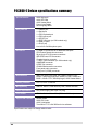
User Guide
Motherboard
P4C800-E
Deluxe
Contents
Features
Notices ........................................................................................... vi
Safety information ......................................................................... vii
About this guide ............................................................................ viii
ASUS contact information ............................................................... x
P4C800-E Deluxe specifications summary .................................... xi
Chapter 1: Product introduction
1.1
1.2
1.3
1.4
Welcome! ........................................................................... 1-1
Package contents ............................................................... 1-1
Special features .................................................................. 1-2
1.3.1 Product highlights .................................................. 1-2
1.3.2 Value-added solutions ............................................ 1-5
Motherboard overview ........................................................ 1-6
1.4.1 Major components ................................................. 1-6
1.4.2 Core specifications ................................................ 1-8
Chapter 2: Hardware information
2.1
2.2
2.3
2.4
2.5
2.6
Motherboard installation ..................................................... 2-1
2.1.1 Placement direction ............................................... 2-1
2.1.2 Screw holes ........................................................... 2-1
Motherboard layout ............................................................ 2-2
Before you proceed ............................................................ 2-3
Central Processing Unit (CPU) ........................................... 2-4
2.4.1 Overview ................................................................ 2-4
2.4.2 Installing the CPU .................................................. 2-5
2.4.3 Installing the heatsink and fan ............................... 2-7
2.4.4 Connecting the CPU fan cable .............................. 2-9
System memory ............................................................... 2-10
2.5.1 Overview .............................................................. 2-10
2.5.2 Memory configurations ........................................ 2-10
2.5.3 Installing a DIMM ................................................. 2-13
2.5.4 Removing a DIMM ............................................... 2-13
Expansion slots ................................................................ 2-14
2.6.1 Installing an expansion card ................................ 2-14
2.6.2 Configuring an expansion card ............................ 2-14
2.6.3 PCI slots .............................................................. 2-16
2.6.4 AGP Pro slot ........................................................ 2-17
2.6.5 Wi-Fi slot .............................................................. 2-18
iii
P4C800-E Deluxe specifications summary
CPU
Socket 478 for Intel® Pentium® 4/Celeron
with speeds up to 3.2+ GHz
On-die 512KB/256KB L2 cache with full speed
Supports Intel® Hyper-Threading Technology
New power design supports next generation Intel Prescott CPU
Chipset
Intel 875P MCH
(features the Intel Performance Acceleration Technology)
Intel ICH5R
Front Side Bus (FSB)
800/533/400 MHz
Memory
Dual-channel memory architecture
4 x 184-pin DDR DIMM sockets for up to 4GB memory
Supports PC3200/2700/2100 unbuffered ECC or non-ECC
DDR DIMMs
Expansion slots
1 x AGP Pro/8X
5 x PCI
1 x Wi-Fi
Storage
Supported by South Bridge (ICH5R)
- 2 x UltraDMA100 connectors
- 2 x Serial ATA connectors (supports RAID0 configuration
under Windows XP)
Supported by Promise® PDC20378 controller (optional)
- 1 x UltraDMA 133 connector
- 2 x Serial ATA connectors
- RAID0, RAID1, RAID0+1, Multi-RAID configurations
IEEE 1394
VIA 6307 IEEE 1394 controller
- supports 2 x IEEE 1394 connectors
LAN
Intel 82547EI Gigabit LAN controller
AI Audio
ADI AD1985 6-channel audio CODEC
AI BIOS
AI BIOS solutions: ASUS CrashFree BIOS 2
ASUS Q-Fan Technology
ASUS POST Reporter™
AI Overclocking
Intelligent CPU frequency tuner
ASUS JumperFree
Adjustable CPU VCORE, memory, and AGP voltages
SFS (Stepless Frequency Selection) from 100MHz to
400MHz at 1MHz increments
C. P. R. (CPU Parameter Recall)
(continued on the next page)
xi
P4C800-E Deluxe specifications summary
Special features
ASUS MyLogo2
ASUS EZ Flash
ASUS Instant Music
Power Loss Restart
Multi-language BIOS
Rear panel I/O
1 x Parallel port
1 x Serial port
1 x PS/2 keyboard port
1 x PS/2 mouse port
1 x S/PDIF Out
1 x IEEE 1394 port (on 1394 models only)
4 x USB 2.0 ports
1 x RJ-45 port
Line In/Line Out/Microphone ports
Internal I/O
2 x USB 2.0 connectors for 4 additional USB ports
CPU/Power/Chassis fan connectors
20-pin/4-pin ATX 12V power connectors
IDE LED/Power LED connectors
Chassis intrusion connector
1 x IEEE 1394 connector (on 1394 models only)
GAME/MIDI connector
S/PDIF Out connector
CD/AUX/Modem audio connectors
Front panel audio connector
Serial port 2 (COM2) connector
BIOS features
4Mb Flash ROM, AMI BIOS, PnP, DMI2.0, WfM2.0, SM
BIOS2.3, Multi-language BIOS, ASUS EZ Flash, CrashFree
BIOS 2, ASUS C.P.R., ASUS MyLogo2, ASUS Instant Music
Industry standard
PCI 2.2, PCI 2.3, USB 2.0
Manageability
WfM 2.0. DMI 2.0, WOL/WOR by PME, chassis intrusion
Power requirement
ATX power supply (with 4-pin 12V plug)
Form Factor
ATX form factor: 12 in x 9.6 in (30.5 cm x 24.5 cm)
Support CD contents
Device drivers
ASUS PC Probe
ASUS LiveUpdate
Trend Micro™ PC-cillin 2002 anti-virus software
Specifications are subject to change without notice.
xii
Chapter 1
This chapter describes the features of the
P4C800-E Deluxe motherboard. It includes
brief explanations of the special attributes of
the motherboard and the new technology it
supports.
Product introduction
Chapter summary
1.1
Welcome! ........................................................ 1-1
1.2
Package contents .......................................... 1-1
1.3
Special features ............................................. 1-2
1.4
Motherboard overview ................................... 1-6
ASUS P4C800-E Deluxe motherboard
1.1
Welcome!
Thank you for buying the ASUS® P4C800-E Deluxe motherboard!
The ASUS P4C800-E Deluxe motherboard delivers a host of new features
and latest technologies making it another standout in the long line of
ASUS quality motherboards!
The motherboard incorporates the Intel® Pentium® 4 Processor in 478-pin
package coupled with the Intel® 875P chipset to set the latest trend for a
powerful desktop platform solution.
Supporting 800 MHz FSB, up to 4GB of system memory with PC3200/
2700/2100 DDR SDRAM, high-resolution graphics via an AGP Pro/8X slot,
Serial ATA support, IEEE 1394, USB 2.0, and 6-channel audio features,
the P4C800-E Deluxe is your perfect vehicle to get ahead in the world of
power computing!
Before you start installing the motherboard, and hardware devices on it,
check the items in your package with the list below.
1.2
Package contents
Check your P4C800-E Deluxe package for the following items.
ASUS P4C800-E Deluxe motherboard
ASUS support CD
InterVideo WinDVD Suite (retail boxes only)
4 x SATA cable
SATA power cable (retail boxes only)
2 x 80-conductor ribbon cables for UltraDMA133/100/66 IDE drives
40-conductor IDE cable
Ribbon cable for a 3.5-inch floppy drive
IEEE 1394 module
4-port USB2.0/GAME module
I/O shield
Bag of extra jumper caps
User Guide
Quick Reference Card (last page of the User Guide)
Quick Setup Guide (retail boxes only)
Jumpers and Connectors Sticker (retail boxes only)
Instant Music keyboard label (retail boxes only)
If any of the above items is damaged or missing, contact your retailer.
ASUS P4C800-E Deluxe motherboard user guide
1-1
1.4
Motherboard overview
Before you install the motherboard, familiarize yourself with its physical
configuration and available features to facilitate the motherboard
installation and future upgrades. A sufficient knowledge of the motherboard
specifications will also help you avoid mistakes that may damage the
board and its components.
1.4.1 Major components
The following are the major components of the P4C800-E Deluxe
motherboard as pointed out in the picture on page 1-7.
1.
CPU socket
18. Wi-Fi slot
2.
North Bridge controller
19. Super I/O controller
3.
ATX12V power connector
20. PCI slots
4.
DDR DIMM sockets
21. Audio CODEC
5.
Floppy disk connector
22. Gigabit LAN controller
6.
IDE connectors
23. PS/2 mouse port
7.
ATX power connector
24. Parallel port
8.
AGP Pro/8X slot
25. IEEE 1394 port (optional)
9.
Standby power LED
26. RJ-45 port
10. Flash ROM
27. Line In jack
11.
28. Line Out jack
Speech controller
12. RAID Ultra ATA133 connector
29. Microphone jack
13. SATA connectors
30. USB 2.0 ports 3 and 4
14. SATA RAID connectors
31. USB 2.0 ports 1 and 2
15. RAID/SATA/IDE controller
32. Serial port
16. South Bridge controller
33. S/PDIF out port
17. IEEE 1394 controller (optional)
34. PS/2 keyboard port
See page 1-8 for the specifications of each component. Refer to
Chapter 2 for detailed information on the components.
1-6
Chapter 1: Product introduction
1
2
3 4
5
6
7
8
22
9
10
21
20
11
19
23
18
17
24
25
1615 14 13 12
26
27
28
29
34
33
32
31
ASUS P4C800-E Deluxe motherboard user guide
30
1-7
1.4.2 Core specifications
1-8
1
CPU socket. A 478-pin surface mount, Zero Insertion Force (ZIF) socket
for the Intel® Pentium® 4 Processor, with 800/533/400 MHz system bus
that allows 6.4GB/s, 4.3GB/s, and 3.2GB/s data transfer rates,
respectively. The socket will support the Intel Prescott CPU when
available.
2
North bridge controller. The Intel® 875P Memory Controller Hub (MCH)
provides the CPU interface, DDR interface, AGP interface, and Hub
Interface. The MCH manages the flow of information between these
interfaces. Designed for use with the Intel® Pentium 4/Celeron
processor, the MCH provides the processor interface with 800/533/400
MHz frequency, system memory interface with up to 6.4GB/s bandwidth
in dual-channel mode, and 0.8V/1.5V AGP Interface Specification 3.0
that supports 8X/4X Fast Write protocol. The MCH interconnects to the
south bridge ICH5R via the Intel® proprietary Hub Interface.
3
ATX 12V connector. This power connector connects the 4-pin 12V plug
from the ATX 12V power supply.
4
DDR DIMM sockets. These four 184-pin DIMM sockets support up to
4GB system memory using unbuffered ECC or non-ECC PC3200/
PC2700/PC2100 DDR DIMMs.
5
Floppy disk connector. This connector accommodates the provided
ribbon cable for the floppy disk drive. One side of the connector is slotted
to prevent incorrect insertion of the floppy disk cable.
6
IDE connectors. These dual-channel bus master IDE connectors support
Ultra DMA/100/66, PIO Modes 3 & 4 IDE devices. Both the primary (blue)
and secondary (black) connectors are slotted to prevent incorrect insertion
of the IDE ribbon cable.
7
ATX power connector. This 20-pin connector connects to an ATX 12V
power supply. The power supply must have at least 1A on the +5V
standby lead (+5VSB).
8
AGP Pro/8X slot. This Accelerated Graphics Port (AGP) Pro slot
supports 0.8V/1.5V AGP 8X mode graphics cards for 3D graphical
applications and delivers up to 2.1GB/s bandwidth.
9
Standby power LED. This LED lights up if there is a standby power on
the motherboard. This LED acts as a reminder to turn off the system
power before plugging or unplugging devices.
10
Flash ROM. This 4Mb firmware hub (FWH) contains the programmable
BIOS program.
Chapter 1: Product introduction
11
Speech controller. This Winbond speech controller supports the
ASUS POST Reporter™ for configurable vocal POST alerts.
12
RAID Ultra ATA133 connector. This connector supports two Ultra
ATA133 HDDs. On RAID models, the HDDs on this connector may be
configured as RAID0, RAID1, or RAID0+1 together with the Serial ATA
HDDs on the SATA RAID connectors.
13
SATA connectors. These connectors support Serial ATA HDDs and
allows for up to 150MB/s data transfer rate using the thin 4-conductor
SATA cables. The HDDs may be configured as RAID 0 level storage
under Windows XP operating system.
14
SATA RAID connectors. These connectors support Serial ATA HDDs
and may be configured as RAID0, RAID1, RAID0+1. Together with the
UltraDMA133 devices, if present, the SATA RAID devices may be set
up as a multi-RAID configuration. (on RAID models only)
15
RAID/SATA/IDE controller. The Promise® PDC20378 RAID controller
provides high-performance RAID0/RAID1/RAID0+1 functionality and
complies with the Serial ATA and UltraDMA 133 specifications.
(on RAID models only)
16
South bridge controller. The fifth-generation Intel I/O Controller Hub
(ICH5R) is a subsystem that integrates various I/O functions including
2-channel ATA/100 bus master IDE controller, SATA RAID controller, up
to eight USB 2.0/1.1 ports, I/O APIC, LPC interface, AC’97 2.3 interface,
and PCI 2.2/2.3 interface. The ICH5 also contains the necessary
arbitration and buffering for efficient utilization of these interfaces.
17
IEEE 1394 controller. The VIA VT6307 controller chipset supports two
low power IEEE 1394 connectors to allow 100Mbps, 200Mbps, and
400Mbps data transfers between the 1394 devices.
(on 1394 models only)
18
Wi-Fi slot. The Wi-Fi (Wireless Fidelity) slot connects a Wi-Fi
equipment for wireless networking that allows 11Mbps transmission
(with a fallback to 5.5, 2, and 1 Mbps) in the 2.4 GHz band. Wi-Fi
networks use radio technologies known as IEEE 802.11b (or later) to
provide a fast reliable wireless connectivity.
19
Super I/O controller. This Winbond Low Pin Count (LPC) interface
provides the commonly used Super I/O functionality. The chipset supports
a high-performance floppy disk controller for a 360K/720K/1.44M/2.88M
floppy disk drive, a multi-mode parallel port, two standard compatible
UARTs, and a Flash ROM interface. This controller also integrates the
ASIC for PC health monitoring.
ASUS P4C800-E Deluxe motherboard user guide
1-9
20
PCI slots. These five 32-bit PCI 2.2 expansion slots support bus
master PCI cards like SCSI or LAN cards with 133MB/s maximum
throughput.
21
Audio CODEC. The AD1985 AC ‘97 2.3 stereo audio CODEC provides
a 6-channel audio capability. The CODEC supports surround sound
output, variable sample rate conversion, analog enumeration
capability, and other major audio technologies for a complete
integrated audio solution.
22
Gigabit LAN controller. The Intel® 82547EI Gigabit Ethernet controller
allows full-duplex Gigabit performance on LAN on Motherboard (LOM)
applications through the Communication Streaming Architecture
(CSA). The controller combines Intel’s fifth-generation Gigabit MAC
design integrated with physical layer circuitry (PHY) to support
1000BASE-T, 100BASE-TX, and 10BASE-T applications.
23
PS/2 mouse port. This green 6-pin connector is for a PS/2 mouse.
24
Parallel port. This 25-pin port connects a parallel printer, a scanner, or
other devices.
25
IEEE 1394 port. This port connects IEEE 1394-compliant devices like
camcorders, VCRs, printers, or digital cameras. (on 1394 models only)
26
RJ-45 port. This port allows connection to a Local Area Network (LAN)
through a network hub.
27
Line In jack. This Line In (light blue) jack connects a tape player or other
audio sources. In 6-channel mode, the function of this jack becomes
Rear Speaker Out.
28
Line Out jack. This Line Out (lime) jack connects a headphone or a
speaker. In 6-channel mode, the function of this jack becomes Front
Speaker Out.
29
Microphone jack. This Mic (pink) jack connects a microphone. In
6-channel mode, the function of this jack becomes Bass/Center.
30
USB 2.0 ports 3 and 4. These 4-pin Universal Serial Bus (USB) ports
are available for connecting USB 2.0 devices.
31
USB 2.0 ports 1 and 2. These 4-pin Universal Serial Bus (USB) ports
are available for connecting USB 2.0 devices.
32
Serial port. This 9-pin COM1 port is for pointing devices or other serial
devices.
33
S/PDIF out port. This connector supports S/PDIF devices that
provides 5.1-channel surround sound and 3D audio.
34
PS/2 keyboard port. This purple connector is for a PS/2 keyboard.
1-10
Chapter 1: Product introduction
Chapter 2
This chapter describes the hardware setup
procedures that you have to perform when
installing system components. It includes
details on the switches, jumpers, and
connectors on the motherboard.
Hardware information
Chapter summary
2.1
Motherboard installation ............................... 2-1
2.2
Motherboard layouts ..................................... 2-2
2.3
Before you proceed ....................................... 2-3
2.4
Central Processing Unit (CPU) ..................... 2-4
2.5
System memory ........................................... 2-10
2.6
Expansion slots ........................................... 2-14
2.7
Jumpers ........................................................ 2-19
2.8
Connectors ................................................... 2-21
ASUS P4C800-E Deluxe motherboard
2.1
Motherboard installation
Before you install the motherboard, study the configuration of your chassis
to ensure that the motherboard fits into it. The motherboard uses the ATX
form factor that measures 12 inches x 9.6 inches (30.5 x 24.5 cm).
Make sure to unplug the power cord before installing or removing the
motherboard. Failure to do so may cause you physical injury and
damage motherboard components.
2.1.1 Placement direction
When installing the motherboard, make sure that you place it into the
chassis in the correct orientation. The edge with external ports goes to the
rear part of the chassis as indicated in the image below.
2.1.2 Screw holes
Place nine (9) screws into the holes indicated by circles to secure the
motherboard to the chassis.
Do not overtighten the screws! Doing so may damage the
motherboard.
Place this side towards
the rear of the chassis
ASUS P4C800-E Deluxe motherboard user guide
2-1
2.2
Motherboard layout
24.5cm (9.6in)
KBPWR
SMB
USBPW34
USB2.0 Top:
T: USB4 RJ-45
B: USB3
Intel 875P
Memory
Controller
Hub (MCH)
Top:Line In
Center:Line Out
Below:Mic In
SEC_IDE
®
30.5cm (12.0in)
Top:
USB2
USB1 1394
ATX Power Connector
Bottom:
DDR DIMM_B2 (64/72 bit,184-pin module)
USBPW12
DDR DIMM_B1 (64/72 bit,184-pin module)
CPU_FAN
DDR DIMM_A2 (64/72 bit,184-pin module)
PWR_FAN
DDR DIMM_A1 (64/72 bit,184-pin module)
COM1
Socket 478
PARALLEL PORT
SPDIF_O
FLOPPY
CR2032 3V
Lithium Cell
CMOS Power
ATX12V
PRI_IDE
PS/2KBMS
T: Mouse
B: Keyboard
4Mbit
Firmware
Hub
PCI1
USB56
SMB20
USBPW78
USBPW56
PCI2
Intel
ICH5R
P4C800-E
USB78
PCI3
AUX
FP_AUDIO
SATA2
SATA1
VIA
VT6307
Chipset
MODEM
Super
I/O
Speech
Controller
CD
PCI4
GAME
CHA_FAN
PCI5
SATA_RAID2
SATA_RAID1
CHASSIS
PRI_RAID
SPDIF_OUT
PROMISE
PDC20378
RAID
Controller
AD1985
CODEC
CLRTC
SB_PWR
Accelerated Graphics Port (AGP_PRO)
Intel
82547EI
Gigabit LAN
PANEL
WIFI
COM2
IE1394_2
TRPWR
The RAID and 1394 features are optional. These components are
grayed out in the above motherboard layout.
2-2
Chapter 2: Hardware information
2.3
Before you proceed
Take note of the following precautions before you install motherboard
components or change any motherboard settings.
1. Unplug the power cord from the wall socket before touching any
component.
2. Use a grounded wrist strap or touch a safely grounded object or to
a metal object, such as the power supply case, before handling
components to avoid damaging them due to static electricity.
3. Hold components by the edges to avoid touching the ICs on them.
4. Whenever you uninstall any component, place it on a grounded
antistatic pad or in the bag that came with the component.
5. Before you install or remove any component, ensure that the
ATX power supply is switched off or the power cord is
detached from the power supply. Failure to do so may cause
severe damage to the motherboard, peripherals, and/or
components.
When lit, the green LED (SB_PWR) indicates that the system is ON, in
sleep mode, or in soft-off mode, a reminder that you should shut down
the system and unplug the power cable before removing or plugging in
any motherboard component.
®
SB_PWR
P4C800-E
P4C800-E Onboard LED
ON
Standby
Power
ASUS P4C800-E Deluxe motherboard user guide
OFF
Powered
Off
2-3
2.4
Central Processing Unit (CPU)
2.4.1 Overview
The motherboard comes with a surface mount 478-pin Zero Insertion
Force (ZIF) socket. The socket is designed for the Intel® Pentium® 4
Processor in the 478-pin package with 512KB L2 cache. The Pentium 4
processor features the Intel® NetBurst™ micro-architecture, HyperThreading Technology, and 800/533/400MHz system bus. Together, these
attributes improve system performance by allowing higher core
frequencies, faster execution of integer instructions, and data transfer
rates up to 6.4GB/s. The socket will also support the Intel Prescott CPU
when available.
Gold Mark
Note in the illustration that the CPU
has a gold triangular mark on one
corner. This mark indicates the
processor Pin 1 that should match a
specific corner of the CPU socket.
Incorrect installation of the CPU into the socket may bend the pins and
severely damage the CPU!
Notes on Intel® Hyper-Threading Technology
1. This motherboard supports Intel Pentium 4 CPUs with HyperThreading Technology.
2. Hyper-Threading Technology is supported under Windows XP and
Linux 2.4.x (kernel) and later versions only. Under Linux, use the
Hyper-Threading compliler to compile the code. If you are using any
other operating systems, disable the Hyper-Threading Techonology
item in BIOS to ensure system stability and performance.
3. It is recommended that you install WinXP Service Pack 1.
4. Make sure to enable the Hyper-Threading Technology item in BIOS
before installing a supported operating system.
5. For more information on Hyper-Threading Technology, visit
www.intel.com/info/hyperthreading.
2-4
Chapter 2: Hardware information
To use the Hyper-Threading Technology on this motherboard:
1. Buy an Intel Pentium 4 CPU that supports Hyper-Threading
Technology. Install the CPU.
2. Power up the system and enter BIOS Setup (see Chapter 4). Under
the Advanced Menu, make sure that the item Hyper-Threading
Technology is set to Enabled. The item appears only if you installed a
CPU that supports Hyper-Threading Techonology.
3. Reboot the computer.
2.4.2 Installing the CPU
Follow these steps to install a CPU.
1. Locate the 478-pin ZIF socket on the motherboard.
2. Unlock the socket by pressing the
lever sideways, then lift it up to a
90°-100° angle.
Socket Lever
90 - 100
Make sure that the socket lever is lifted up to 90°-100° angle,
otherwise the CPU does not fit in completely.
ASUS P4C800-E Deluxe motherboard user guide
2-5
3. Position the CPU above the
socket such that its marked
corner matches the base of the
socket lever.
4. Carefully insert the CPU into the
socket until it fits in place.
Gold Mark
The CPU fits only in one correct orientation. DO NOT force the CPU
into the socket to prevent bending the pins and damaging the CPU!
5. When the CPU is in place, push
down the socket lever to secure
the CPU. The lever clicks on the
side tab to indicate that it is
locked.
2-6
Chapter 2: Hardware information
2.4.3 Installing the heatsink and fan
The Intel® Pentium® 4 Processor requires a specially designed heatsink
and fan assembly to ensure optimum thermal condition and performance.
When you buy a boxed Intel Pentium 4 Processor, the package
includes the heatsink, fan, and retention mechanism.
In case you buy a CPU separately, make sure that you use only Intel
certified heatsink and fan.
Follow these steps to install the CPU heatsink and fan.
1. Place the heatsink on top of the installed CPU, making sure that the
heatsink fits properly on the retention module base.
The retention module base is already installed on the motherboard
upon purchase.
You do not have to remove the retention module base when installing
the CPU or installing other motherboard components.
CPU Heatsink
Retention Module Base
Your boxed Intel Pentium 4 Processor package should come with
installation instructions for the CPU, heatsink, and the retention
mechanism. If the instructions in this section do not match the CPU
documentation, follow the latter.
ASUS P4C800-E Deluxe motherboard user guide
2-7
2. Position the fan with the retention mechanism on top of the heatsink.
Align and snap the four hooks of the retention mechanism to the holes
on each corner of the module base.
Make sure that the fan and retention mechanism assembly perfectly
fits the heatsink and module base, otherwise you cannot snap the
hooks into the holes.
Retention Hole
Retention Lock
Retention Hook Snapped
to the Retention Hole
Keep the retention locks lifted upward while fitting the retention
mechanism to the module base.
2-8
Chapter 2: Hardware information
3. Push down the locks on the retention mechanism to secure the
heatsink and fan to the module base.
When secure, the retention locks should point to opposite directions.
2.4.4 Connecting the CPU fan cable
When the fan, heatsink, and the retention mechanism are in place,
connect the CPU fan cable to the connector on the motherboard labeled
CPU_FAN.
CPU Fan Connector
(CPU_FAN)
Don’t forget to connect the CPU fan connector! Hardware monitoring
errors may occur if you fail to plug this connector.
ASUS P4C800-E Deluxe motherboard user guide
2-9
2.5
System memory
2.5.1 Overview
The motherboard comes with four Double Data Rate (DDR) Dual Inline
Memory Module (DIMM) sockets. These sockets support up to 4GB
system memory using 184-pin unbuffered ECC or non-ECC PC3200/
PC2700/PC2100 DDR DIMMs, and allow up to 6.4GB/s data transfer rate.
104 Pins
DIMM_B2
DIMM_B1
DIMM_A2
DIMM_A1
The following figure illustrates the location of the DDR DIMM sockets.
80 Pins
®
P4C800-E
P4C800-E 184-Pin DDR DIMM Sockets
2.5.2 Memory configurations
You may install 64MB, 128MB, 256MB, 512MB, and 1GB DDR DIMMs into
the DIMM sockets using the memory configurations in this section.
Important notes
1. Installing DDR DIMMs other than the recommended configurations
may cause memory sizing error or system boot failure. Use any of
the recommended configurations in Table 1.
2. In dual-channel configurations, install only identical (the same
type and size) DDR DIMM pairs for each channel.
3. Always install DIMMs with the same CAS latency. For optimum
compatibility, it is recommended that you obtain memory modules
from the same vendor.
4. Make sure that the memory frequency matches the CPU FSB
(Front Side Bus). Refer to Table 2.
5. DIMMs installed into any three sockets will function in singlechannel mode.
6. When all four sockets are populated with 1GB DIMMs (total 4GB),
the system may detect only 3+GB (a little less than 4GB) due to
ICH5R resource allocation.
2-10
Chapter 2: Hardware information
Table 1
Recommended memory configurations
Mode
DIMM_A1
(blue)
Single-channel
Dual-channel
Sockets
DIMM_A2 DIMM_B1
(black)
(blue)
DIMM_B2
(black)
(1) Populated
—
—
—
(2)
—
Populated
—
—
(3)
—
—
Populated
—
(4)
—
—
—
Populated
—
Populated
—
(1) Populated
(2)
—
Populated
—
Populated
(3)* Populated Populated Populated Populated
* For dual-channel configuration (3), you may:
• install identical DIMMs in all four sockets
or
• install identical DIMM pair in DIMM_A1 and DIMM_B1 (blue sockets)
and identical DIMM pair in DIMM_A2 and DIMM_B2 (black sockets)
Table 2
Memory frequency/CPU FSB synchronization
CPU FSB
DDR DIMM Type
Memory Frequency
800 MHz
PC3200/PC2700*/PC2100
400/333*/266 MHz
533 MHz
PC2700/PC2100
333/266 MHz
400 MHz
PC2100
266 MHz
*When using 800MHz CPU FSB, PC2700 DDR DIMMs may run only at
320MHz (not 333MHz) due to chipset limitation.
ASUS P4C800-E Deluxe motherboard user guide
2-11
Table 3
Size
DDR400 Qualified Vendor List (QVL)
Vendor
Model
Brand
Component
Max. DIMMs
256MB
Transcend
TS32MLD64V4F3
Samsung
K4H560838D-TCC4
2
512MB
Transcend
TS64MLD64V4F3
Samsung
K4H560838D-TCC4
2
256MB
Transcend
TS32MLD64V4F3
Mosel
V58C2256804SAT5
4
512MB
Transcend
TS64MLD64V4F3
Mosel
V58C2256804SAT5
2
256MB
Kingston
KVR400X64C25/256
Winbond
W942508BH-5
4
512MB
Kingston
KVR400X64C25/512
Winbond
W942508BH-5
2
256MB
Kingston
KVR400X72C25/256
Winbond
W942508BH-5(ECC)
2
512MB
Kingston
KVR400X72C25/512
Winbond
W942508BH-5(ECC)
2
256MB
Winbond
W9425GCDB-5
Winbond
W942508CH-5
4
512MB
Winbond
W9451GCDB-5
Winbond
W942508CH-5
4
128MB
Infineon
HYS64D16301GU-5-B
Infineon
HYB25D256160BT-5B
4
256MB
Infineon
HYS64D32300GU-5-B
Infineon
HYB25D256800BT-5B
4
512MB
Infineon
HYS64D64320GU-5-B
Infineon
HYB25D256800BT-5B
2
256MB
Samsung
M381L3223ETM-CCC
Samsung
K4H560838E-TCCC(ECC)
4
512MB
Samsung
M381L6423ETM-CCC
Samsung
K4H560838E-TCCC(ECC)
4
128MB
Micron
MT8VDDT1664AG-403B2
Micron
MT46V16M8-5ESB
1
256MB
Micron
MT16VDDT3264AG-403B2
Micron
MT46V16M8-5ESB
1
256MB
Micron
MT16VDDT3264AG-403B5
Micron
MT46V16M8-5TESB
2
256MB
Hynix
HYMD232646B8J-D43 AA
Hynix
HY5DU56822BT-D43
4
512MB
Hynix
HYMD264646B8J-D43 AA
Hynix
HY5DU56822BT-D43
4
256MB
TwinMos
M2G9I08AFATT9F081AA4T
TwinMos
TMD7608F8E50D
1
512MB
TwinMos
M2G9J16AGATT9F081AA4T
TwinMos
TMD7608F8E50D
1
256MB
Apacer
77.10636.465
Samsung
K4H560838D-TCC4
4
512MB
Apacer
77.10736.464
Samsung
K4H560838D-TCC4
2
256MB
ADATA
MDOAD5F3G315B1ECZ
ADATA
ADD8608A8A-5B
2
256MB
ADATA
MDOSS6F3G31JB1EAE
Samsung
K4H560838D-TCC4
2
256MB
ADATA
MDOWB5F3G316B1EAE
Winbond
W942508BH-5
4
512MB
PSC
AL6D8A53T1-5B
PSC
A2S56D30ATP
4
256MB
CORSAIR
CMX256A-3500C2
Winbond
W942508BH-5
2
512MB
CORSAIR
CMX512-3500C2
Winbond
W942508BH-5
2
512MB
KINGMAX
MPXC22D-38KT3R
Kingmax
KDL388P4EA-50
1
256MB
Micron
MT8VDDT3264AG-40BC4
Micron
MT46V32M8TG-5BC
4
512MB
Micron
MT16VDDT6464AG-40BC4
Micron
MT46V32M8TG-5BC
4
256MB
ATP
AG32L64T8SQC4S
Samsung
K4H560838D-TCC4
1
512MB
ATP
AG64L64T8SQC4S
Samsung
K4H560838D-TCC4
1
512MB
TAKEMS
MS64D64020U-5
TAKEMS
MS25D25680S-5
2
256MB
OCZ
N/A
OCZ
X4W560840A-40
2
Obtain DDR DIMMs only from ASUS qualified vendors for better
system performance. Visit the ASUS website (www.asus.com) for the
latest QVL.
2-12
Chapter 2: Hardware information
2.5.3 Installing a DIMM
Make sure to unplug the power supply before adding or removing
DIMMs or other system components. Failure to do so may cause
severe damage to both the motherboard and the components.
Follow these steps to install a DIMM.
DDR DIMM notch
1. Unlock a DIMM socket by
pressing the retaining clips
outward.
2. Align a DIMM on the socket such
that the notch on the DIMM
matches the break on the socket.
Unlocked Retaining Clip
A DDR DIMM is keyed with a notch so that it fits in only one direction.
DO NOT force a DIMM into a socket to avoid damaging the DIMM.
3. Firmly insert the DIMM into the
socket until the retaining clips
snap back in place and the DIMM
is properly seated.
Locked Retaining Clip
2.5.4 Removing a DIMM
Follow these steps to remove a DIMM.
1. Simultaneously press the
retaining clips outward to unlock
the DIMM.
Support the DIMM lightly with your fingers when pressing the retaining
clips. The DIMM might get damaged when it flips out with extra force.
2. Remove the DIMM from the socket.
ASUS P4C800-E Deluxe motherboard user guide
2-13
2.6
Expansion slots
In the future, you may need to install expansion cards. The motherboard
has five PCI slots, one Accelerated Graphics Port (AGP) Pro slot, and a
Wi-Fi slot. The following sub-sections describe the slots and the expansion
cards that they support.
Make sure to unplug the power cord before adding or removing
expansion cards. Failure to do so may cause you physical injury and
damage motherboard components.
2.6.1 Installing an expansion card
Follow these steps to install an expansion card.
1. Before installing the expansion card, read the documentation that
came with it and make the necessary hardware settings for the card.
2. Remove the system unit cover (if your motherboard is already installed
in a chassis).
3. Remove the bracket opposite the slot that you intend to use. Keep the
screw for later use.
4. Align the card connector with the slot and press firmly until the card is
completely seated on the slot.
5. Secure the card to the chassis with the screw you removed earlier.
6. Replace the system cover.
2.6.2 Configuring an expansion card
After installing the expansion card, configure the it by adjusting the
software settings.
1. Turn on the system and change the necessary BIOS settings, if any.
See Chapter 4 for information on BIOS setup.
2. Assign an IRQ to the card. Refer to the tables on the next page.
3. Install the software drivers for the expansion card.
2-14
Chapter 2: Hardware information
Standard Interrupt Assignments
IRQ
0
1
2
3*
4*
5*
6
7*
8
9*
10*
11*
12*
13
14*
15*
*
Priority
1
2
N/A
11
12
13
14
15
3
4
5
6
7
8
9
10
Standard Function
System Timer
Keyboard Controller
Programmable Interrupt
Communications Port (COM2)
Communications Port (COM1)
Sound Card (sometimes LPT2)
Floppy Disk Controller
Printer Port (LPT1)
System CMOS/Real Time Clock
ACPI Mode when used
IRQ Holder for PCI Steering
IRQ Holder for PCI Steering
PS/2 Compatible Mouse Port
Numeric Data Processor
Primary IDE Channel
Secondary IDE Channel
These IRQs are usually available for ISA or PCI devices.
IRQ assignments for this motherboard
A
B
PCI slot 1
—
—
PCI slot 2
—
—
PCI slot 3
—
—
PCI slot 4
—
—
PCI slot 5
—
—
AGP Pro slot
shared used
Onboard USB controller HC0 shared —
Onboard USB controller HC1 —
—
Onboard USB controller HC2 —
—
Onboard USB controller HC3 shared —
Onboard USB 2.0 controller
—
—
Onboard LAN (optional)
—
—
Onboard SATA (optional)
—
—
Onboard 1394 (optional)
—
—
C
—
—
—
—
—
—
—
—
used
—
—
—
—
—
D
E
F
G
H
—
— shared —
—
—
—
— shared —
—
—
—
— shared
— shared —
—
—
—
— shared —
—
—
—
—
—
—
—
—
—
—
—
used
—
—
—
—
—
—
—
—
—
—
—
—
—
—
—
—
—
— shared
—
—
— shared —
—
—
—
— shared
— shared —
—
—
When using PCI cards on shared slots, ensure that the drivers support
“Share IRQ” or that the cards do not need IRQ assignments.
Otherwise, conflicts will arise between the two PCI groups, making the
system unstable and the card inoperable.
ASUS P4C800-E Deluxe motherboard user guide
2-15
2.6.3 PCI slots
There are five 32-bit PCI slots on this motherboard. The slots support PCI
cards such as a LAN card, SCSI card, USB card, and other cards that
comply with PCI specifications.
1. The PCI 5 slot and the Wi-Fi slot may not be used at the same time.
2. When installing long PCI cards, it is recommended that you install
them in PCI slots 1, 2, or 5. Long PCI cards installed in PCI slots 3
and 4 may interfere with the SATA and GAME connectors.
2-16
Chapter 2: Hardware information
2.6.4 AGP Pro slot
This motherboard has an Accelerated Graphics Port (AGP) Pro slot that
supports AGP 8X (+0.8V) cards and AGP 4X (+1.5V) cards. When you buy
an AGP card, make sure that you ask for one with +0.8V or +1.5V
specification.
Note the notches on the card golden fingers to ensure that they fit the AGP
slot on your motherboard.
Install only +0.8V or +1.5V AGP cards. This motherboard does not
support 3.3V AGP cards.
®
P4C800-E
Keyed for 1.5v
P4C800-E Accelerated Graphics Port (AGP)
If installing the ATi 9500 or 9700 Pro Series VGA cards, use only the
card version PN xxx-xxxxx-30 or later, for optimum performance and
overclocking stability.
ASUS P4C800-E Deluxe motherboard user guide
2-17
2.6.5 Wi-Fi slot
The Wi-Fi (Wireless Fidelity) slot will support the ASUS Wi-Fi module
when available. Visit the ASUS website (www.asus.com) for product
updates.
The Wi-Fi slot conforms to the Institute of Electrical and Electronics
Engineers (IEEE) 802.11b standard for wireless devices operating in the
2.4 GHz frequency band.
®
WIFI
P4C800-E
P4C800-E WIRELESS Connectors
The PCI 5 slot and the Wi-Fi slot may not be used at the same time.
IEEE 802.11b introduction
The IEEE 802.11b standard includes provisions for three radio
technologies: direct sequence spread spectrum, frequency hopping
spread spectrum, and infrared. Devices that comply with the 802.11b
standard operate at data rates of up to 11 Mbps for direct sequence
spread spectrum.
The IEEE 802.11b specification allocates the 2.4 GHz frequency band into
14 overlapping operating channels. Each Channel corresponds to a
different set of frequencies. If operating multiple 802.11b wireless PCI
cards in the same vicinity, the distance between the center frequencies
must be at least 25 MHz to avoid interference.
The channels available to an 802.11b wireless PCI card will vary from
country to country. In the United States, the 802.11b standard allocates 11
operating channels for direct sequence devices. Channels 1, 6, and 11 are
independent and do not overlap with each other.
2-18
Chapter 2: Hardware information
2.7
Jumpers
1. Keyboard power (3-pin KBPWR)
This jumper allows you to enable or disable the keyboard wake-up
feature. Set this jumper to pins 2-3 (+5VSB) if you wish to wake up the
computer when you press a key on the keyboard (the default is the
Space Bar). This feature requires an ATX power supply that can supply
at least 1A on the +5VSB lead, and a corresponding setting in the
BIOS (see section 4.5.1 Power Up Control).
KBPWR
1 2
®
+5V
(Default)
2 3
+5VSB
P4C800-E
P4C800-E Keyboard Power Setting
2. Clear RTC RAM (CLRTC)
This jumper allows you to clear the Real Time Clock (RTC) RAM in
CMOS. You can clear the CMOS memory of date, time, and system
setup parameters by erasing the CMOS RTC RAM data. The RAM
data in CMOS, that include system setup information such as system
passwords, is powered by the onboard button cell battery.
To erase the RTC RAM:
1. Turn OFF the computer and unplug the power cord.
2. Move the jumper cap from pins 1-2 (default) to pins 2-3. Keep the
cap on pins 2-3 for about 5~10 seconds, then move the cap back
to pins 1-2.
3. Plug the power cord and turn ON the computer.
4. Hold down the <Del> key during the boot process and enter BIOS
setup to re-enter data.
Except when clearing the RTC RAM, never remove the cap on CLRTC
jumper default position. Removing the cap will cause system boot
failure!
ASUS P4C800-E Deluxe motherboard user guide
2-19
CLRTC
®
1 2
2 3
P4C800-E
Normal
(Default)
Clear CMOS
P4C800-E Clear RTC RAM
You do not need to clear the RTC when the system hangs due to
overclocking. For system failure due to overclocking, use the C.P.R.
(CPU Parameter Recall) feature. Shut down and reboot the system so
BIOS can automatically reset parameter settings to default values.
3. USB device wake-up (3-pin USBPW12, USBPW34, USBPW56,
USBPW78)
Set these jumpers to +5V to wake up the computer from S1 sleep
mode (CPU stopped, DRAM refreshed, system running in low power
mode) using the connected USB devices. Set to +5VSB to wake up
from S3 and S4 sleep modes (no power to CPU, DRAM in slow
refresh, power supply in reduced power mode).
The USBPWR12 and USBPWR34 jumpers are for the rear USB ports.
The USBPWR56 and USBPWR78 jumper is for the internal USB
header that you can connect to the front USB ports.
USBPW12
2
1
+5V
(Default)
1 2
3
2
+5VSB
2 3
USBPW34
®
+5V
(Default)
P4C800-E
USBPW78
USBPW56
P4C800-E USB Device Wake Up
1 2
+5V
(Default)
+5VSB
2 3
+5VSB
1. The USB device wake-up feature requires a power supply that can
provide 500mA on the +5VSB lead for each USB port. Otherwise,
the system would not power up.
2. The total current consumed must NOT exceed the power supply
capability (+5VSB) whether under normal condition or in sleep
mode.
2-20
Chapter 2: Hardware information
4. SMB2.0 (two 3-pin SMB20)
These jumpers allow you to enable or disable the SMBus 2.0 feature
supported on the motherboard. By default, pins 2-3 are shorted
(jumper caps on) to disable the feature. If you wish to install PCI
devices that comply with SMBus 2.0 specification, move the jumper
caps to pins 1-2 of both jumpers to enable the SMBus 2.0 feature.
SMB20
®
2 3
1 2
P4C800-E
Disable
(Default)
Enable
P4C800-E SMB20 Setting
2.8
Connectors
This section describes and illustrates the internal connectors on the
motherboard.
Always connect ribbon cables with the red stripe to Pin 1 on the
connectors. Pin 1 is usually on the side closest to the power connector
on hard drives and CD-ROM drives, but may be on the opposite side
on floppy disk drives.
1. Floppy disk drive connector (34-1 pin FLOPPY)
This connector supports the provided floppy drive ribbon cable. After
connecting one end to the motherboard, connect the other end to the
floppy drive. (Pin 5 is removed to prevent incorrect insertion when
using ribbon cables with pin 5 plug).
FLOPPY
PIN 1
®
NOTE: Orient the red markings on
the floppy ribbon cable to PIN 1.
P4C800-E
P4C800-E Floppy Disk Drive Connector
ASUS P4C800-E Deluxe motherboard user guide
2-21
2. IDE connectors (40-1 pin PRI_IDE[blue], SEC_IDE [black)
This connector supports the provided UltraDMA/100/66 IDE hard disk
ribbon cable. Connect the cable’s blue connector to the primary
(recommended) or secondary IDE connector, then connect the gray
connector to the UltraDMA/100/66 slave device (hard disk drive) and
the black connector to the UltraDMA/100/66 master device. It is
recommended that you connect non-UltraDMA/100/66 devices to the
secondary IDE connector. If you install two hard disks, you must
configure the second drive as a slave device by setting its jumper
accordingly. Refer to the hard disk documentation for the jumper
settings. BIOS supports specific device bootup. You may configure two
hard disks to be both master devices with two ribbon cables – one for
the primary IDE connector and another for the secondary IDE
connector.
1. Pin 20 on each IDE connector is removed to match the covered hole
on the UltraDMA cable connector. This prevents incorrect orientation
when you connect the cables.
2. The hole near the blue connector on the UltraDMA/100/66 cable is
intentional.
P4C800-E
PIN 1
P4C800-E IDE Connectors
NOTE: Orient the red markings
(usually zigzag) on the IDE
ribbon cable to PIN 1.
PRI_IDE
®
SEC_IDE
3. For UltraDMA/100/66 IDE devices, use the 80-conductor IDE cable.
PIN 1
Important note when using legacy OS
Refer to page 2-24 on how to configure P-ATA and S-ATA devices if
you installed a legacy operating system (e.g. MS-DOS, Windows 98/
Me/NT4.0).
2-22
Chapter 2: Hardware information
3. Serial ATA connectors (7-pin SATA1, SATA2)
These next generation connectors support the thin Serial ATA cables
for Serial ATA hard disks. The current Serial ATA interface allows up to
150 MB/s data transfer rate, faster than the standard parallel ATA with
133 MB/s (Ultra ATA/133).
If you installed Serial ATA hard disks, you may create a RAID 0
configuration using the RAID feature of the Intel ICH5R chipset. See
section “5.4 Intel RAID for Serial ATA” for information on creating a
RAID.
GND
RSATA_RXP2
RSATA_RXN2
GND
RSATA_TXN2
RSATA_TXP2
GND
SATA2
®
SATA1
P4C800-E SATA Connectors
GND
RSATA_RXP1
RSATA_RXN1
GND
RSATA_TXN1
RSATA_TXP1
GND
P4C800-E
Important notes on Serial ATA
1. In a legacy operating system (DOS, Windows 98, Windows Me,
Windows NT) environment, using the Serial ATA connectors will
disable the ICHR chipset support to one of the IDE channels
(either primary or secondary channel).
2. The Serial ATA RAID feature (RAID 0) is available only if you are
using Windows XP.
ASUS P4C800-E Deluxe motherboard user guide
2-23
Parallel ATA and Serial ATA device configurations
Following are the Parallel ATA and Serial ATA device configurations
supported by Intel ICH5 specifications.
Native operating systems (OS) are Windows 2000/XP. ICH5 supports a
maximum of six (6) devices using these OS.
Legacy OS are MS-DOS, Windows 98/Me/NT4.0. ICH5 supports a
maximum of four (4) devices using these OS.
Operating System
Primary
(2 devices)
P-ATA
Secondary
Port 0
(2 devices)
S-ATA
Port 1
(1 device)
(1 device)
—
—
1. Windows 2000/XP
2. Windows 98/Me/NT4.0
Configuration A
—
Configuration B
—
Configuration C
Legend:
—
Supported
Disabled
Required IDE Configuration settings in BIOS
Refer to the following table for the appropriate BIOS settings of the above
P-ATA and S-ATA device configurations. See section “4.3.6 IDE
Configuration” for details on the related BIOS items.
BIOS item
Onboard IDE Operate Mode
Windows
2000/XP
Enhanced Mode
Enhanced Mode Support On S-ATA
IDE Port Settings
2-24
—
A
Windows 98/Me/NT4.0
B
Compatible Mode
Compatible Mode
C
Compatible Mode
—
—
—
Primary P-ATA+S-ATA
Sec. P-ATA+S-ATA
P-ATA Ports Only
Chapter 2: Hardware information
4. Serial ATA RAID connectors (7-pin SATA_RAID1, SATA_RAID2)
(on RAID models only)
These Serial ATA connectors support SATA hard disks that you may
configure as a RAID set. Through the onboard Promise® PDC20378
RAID controller, you may create a RAID0, RAID1, RAID0+1, or multiRAID configuration together with the RAID ATA133 connector. See
Chapter 5 for details on RAID configuration.
GND
RSATA_TXP2
RSATA_TXN2
GND
RSATA_RXP2
RSATA_RXN2
GND
SATA_RAID2
®
SATA_RAID1
P4C800-E SATA RAID Connectors
GND
RSATA_TXP1
RSATA_TXN1
GND
RSATA_RXP1
RSATA_RXN1
GND
P4C800-E
1. If you wish to create a RAID set, make sure that you have
connected the SATA cable and installed Serial ATA devices. You
cannot enter the SATARaid™ utility and SATA BIOS setup during
POST if there are no connected Serial ATA devices.
2. The Promise PDC20376 RAID controller does not support ATAPI
devices such as CD-ROMs, DVD-ROMs, etc.
ASUS P4C800-E Deluxe motherboard user guide
2-25
5. RAID ATA/133/100/66/33 connector (40-1 pin PRI_RAID)
(on RAID models only)
This connector supports either RAID 0 or RAID 1 configuration through
the onboard Promise® PDC20378 controller. You can connect two
UltraATA133 hard disks to this connector and set up a disk array
configuration. You may also set up the UltraATA133 hard disks with the
Serial ATA hard disks on the Serial ATA RAID connectors to create a
multi-RAID configuration. See Chapter 5 for details on RAID
configuration.
PIN 1
PRI_RAID
®
NOTE: Orient the red markings
(usually zigzag) on the IDE
ribbon cable to PIN 1.
P4C800-E
P4C800-E RAID Connector
1. If you wish to create a RAID set using UltraATA hard disks, make
sure that you have connected the UltraATA cable and installed
UltraATA 133 hard disks.
2. The Promise PDC20376 RAID controller does not support ATAPI
devices such as CD-ROMs, DVD-ROMs, etc.
6. SMBus connector (6-1 pin SMB)
This connector allows you to connect SMBus (System Management
Bus) devices. Devices communicate with an SMBus host and/or other
SMBus devices using the SMBus interface.
SMB
P4C800-E
Ground
SMBDATA
+3V
®
FLOATING
SMBCLK
1
P4C800-E SMBus Connector
2-26
Chapter 2: Hardware information
7. Chassis intrusion connector (4-1 pin CHASSIS)
This lead is for a chassis designed with intrusion detection feature.
This requires an external detection mechanism such as a chassis
intrusion sensor or microswitch. When you remove any chassis
component, the sensor triggers and sends a high-level signal to this
lead to record a chassis intrusion event.
By default, the pins labeled “Chassis Signal” and “Ground” are shorted
with a jumper cap. If you wish to use the chassis intrusion detection
feature, remove the jumper cap from the pins.
P4C800-E
Chassis Signal
GND
®
+5VSB_MB
CHASSIS
(Default)
P4C800-E Chassis Alarm Lead
8. CPU, Chassis, and Power Fan Connectors
(3-pin CPU_FAN, PWR_FAN, CHA_FAN)
The fan connectors support cooling fans of 350mA~740mA (8.88W
max.) or a total of 1A~2.22A (26.64W max.) at +12V. Connect the fan
cables to the fan connectors on the motherboard, making sure that the
black wire of each cable matches the ground pin of the connector.
Do not forget to connect the fan cables to the fan connectors. Lack of
sufficient air flow within the system may damage the motherboard
components. These are not jumpers! DO NOT place jumper caps on
the fan connectors!
Rotation
+12V
GND
GND
+12V
Rotation
PWR_FAN CPU_FAN
®
CHA_FAN
P4C800-E
GND
+12V
Rotation
P4C800-E 12-Volt Fan Connectors
ASUS P4C800-E Deluxe motherboard user guide
2-27
9. ATX power connectors (20-pin ATXPWR, 4-pin ATX12V)
These connectors connect to an ATX 12V power supply. The plugs
from the power supply are designed to fit these connectors in only one
orientation. Find the proper orientation and push down firmly until the
connectors completely fit.
In addition to the 20-pin ATXPWR connector, this motherboard requires
that you connect the 4-pin ATX +12V power plug to provide sufficient
power to the CPU.
1. Do not forget to connect the 4-pin ATX +12V power plug.
Otherwise, the system does not boot up.
2. Make sure that your ATX 12V power supply can provide 8A on the
+12V lead and at least 1A on the +5-volt standby lead (+5VSB).
The minimum recommended wattage is 230W, or 300W for a fully
configured system. The system may become unstable or may not
boot up if the power is inadequate.
ATX12V1
GND +12V DC
®
GND +12V DC
P4C800-E
ATXPWR1
+3.3VDC
-12.0VDC
GND
PS_ON#
GND
GND
GND
-5.0VDC
+5.0VDC
+5.0VDC
+3.3VDC
+3.3VDC
GND
+5.0VDC
GND
+5.0VDC
GND
PWR_OK
+5VSB
+12.0VDC
P4C800-E ATX Power Connector
10. Power supply thermal connector (2-pin TRPWR)
If your power supply has a thermal monitoring feature, connect its
thermal sensor cable to this connector.
P4C800-E
TRPWR
Ground
TRPWR
®
P4C800-E Power Supply Thermal Connector
2-28
Chapter 2: Hardware information
11. Digital audio connector (4-1 pin SPDIF_OUT)
In addition to the S/PDIF Out port on the rear panel, an S/PDIF Out
connector is available for an S/PDIF audio module. Connect one end
of the S/PDIF audio cable this connector and the other end to the
S/PDIF module.
The S/PDIF module is purchased separately.
+5V
®
SPDIFOUT
GND
SPDIF_OUT
P4C800-E
P4C800-E Digital Audio Connector
12. GAME/MIDI connector (16-1 pin GAME)
This connector supports an optional GAME/MIDI module. Connect the
GAME/MIDI cable to this connector. The GAME/MIDI port on the
module connects a joystick or a game pad for playing games, and MIDI
devices for playing or editing audio files.
+5V
J1B2
J1CY
GND
GND
J1CX
J1B1
+5V
®
P4C800-E
P4C800-E Game Connector
MIDI_IN
J2B2
J2CY
MIDI_OUT
J2CX
J2B1
+5V
GAME
ASUS P4C800-E Deluxe motherboard user guide
2-29
13. USB headers (10-1 pin USB56, USB78)
If the USB ports on the rear panel are inadequate, two USB headers
are available for additional USB ports. The USB header complies with
USB 2.0 specification that supports up to 480 Mbps connection speed.
This speed advantage over the conventional 12 Mbps on USB 1.1
allows faster Internet connection, interactive gaming, and simultaneous
running of high-speed peripherals.
Connect an optional USB 2.0/GAME module to this header. The
module has two USB 2.0 ports that support the next generation USB
peripherals such as high resolution cameras, scanners, and printers.
P4C800-E USB 2.0 Header
1
USB78
1
USB+7V
USB_P7USB_P7+
GND
USB56
USB+5V
USB_P5USB_P5+
GND
P4C800-E
USB+8V
USB_P8USB_P8+
GND
NC
USB+6V
USB_P6USB_P6+
GND
NC
®
NEVER connect a 1394 cable to the either USB56 or USB78
connector. Doing so will damage the motherboard!
2-30
Chapter 2: Hardware information
®
P4C800-E
AUX(White)
CD(Black)
Left Audio Channel
Ground
Ground
Right Audio Channel
Modem-Out
Ground
Ground
Modem-In
MODEM
Left Audio Channel
Ground
Ground
Right Audio Channel
14. Internal audio connectors (4-pin CD, AUX, MODEM)
These connectors allow you to receive stereo audio input from sound
sources such as a CD-ROM, TV tuner, or MPEG card. The MODEM
connector allows the onboard audio to interface with a voice modem
card with a similar connector. It also allows the sharing of mono_in
(such as a phone) and a mono_out (such as a speaker) between the
audio and a voice modem card.
P4C800-E Internal Audio Connectors
15. IEEE 1394 connector (10-1 pin IE1394_2) (on 1394 models only)
This connector is for an optional 1394 module. Attach the 10-1 pin
1394 cable plug from the module to this connector. You may also
connect a 1394-compliant internal hard disk to this connector.
TPA0GND
TPB0+12V
GND
®
P4C800-E
1
P4C800-E IEEE-1394 Connector
TPA0+
GND
TPB0+
+12V
IE1394_2
NEVER connect a USB cable to the IEEE 1394 connector. Doing so
will damage the motherboard!
ASUS P4C800-E Deluxe motherboard user guide
2-31
®
BLINE_OUT_L
AGND
+5VA
BLINE_OUT_R
16. Front panel audio connector (10-1 pin FP_AUDIO)
This is an interface for the Intel front panel audio cable that allow
convenient connection and control of audio devices.
By default, the pins labeled LINE OUT_R/BLINE_OUT_R and the pins
LINE OUT_L/BLINE_OUT_L are shorted with jumper caps. Remove
the caps only when you are connecting the front panel audio cable.
FP_AUDIO
MIC2
MICPWR
Line out_R
NC
Line out_L
P4C800-E
P4C800-E Front Panel Audio Connector
17. Serial port 2 connector (10-1 pin COM2)
This connector accommodates a second serial port using an optional
serial port bracket. Connect the bracket cable to this connector then
install the bracket into a slot opening at the back of the system chassis.
The serial port bracket (COM2) is purchased separately.
COM2
®
PIN 1
P4C800-E
P4C800-E Serial COM2 Bracket
2-32
Chapter 2: Hardware information
18. System panel connector (20-pin PANEL)
This connector accommodates several system front panel functions.
P4C800-E
SMI Lead
+5V
Ground
Ground
Speaker
PLED-
IDE_LED
Reset
Ground
®
ExtSMI#
Ground
PWR
Ground
IDE_LED+
IDE_LED-
PLED+
Power LED
Speaker
Connector
Reset SW
ATX Power
Switch*
* Requires an ATX power supply.
P4C800-E System Panel Connectors
• System Power LED Lead (3-1 pin PLED)
This 3-1 pin connector connects to the system power LED. The LED
lights up when you turn on the system power, and blinks when the
system is in sleep mode.
• Hard Disk Activity Lead (2-pin IDELED)
This 2-pin connector is for the HDD LED cable. The read or write
activities of the device connected to the any of IDE connectors cause
the IDE LED to light up.
• System Warning Speaker Lead (4-pin SPKR)
This 4-pin connector connects to the case-mounted speaker and
allows you to hear system beeps and warnings.
• System Management Interrupt Lead (2-pin SMI)
This 2-pin connector allows you to manually place the system into a
suspend mode, or “green” mode, where system activity is instantly
decreased to save power and to expand the life of certain system
components. Attach the case-mounted suspend switch to this 2-pin
connector.
• ATX Power Switch / Soft-Off Switch Lead (2-pin PWRBTN)
This connector connects a switch that controls the system power.
Pressing the power switch turns the system between ON and SLEEP,
or ON and SOFT OFF, depending on the BIOS or OS settings.
Pressing the power switch while in the ON mode for more than 4
seconds turns the system OFF.
• Reset Switch Lead (2-pin RESET)
This 2-pin connector connects to the case-mounted reset switch for
rebooting the system without turning off the system power.
ASUS P4C800-E Deluxe motherboard user guide
2-33