1
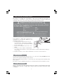
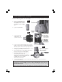
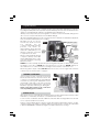
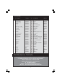
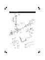
BANDIT
AIR COMPRESSOR
OPERATION & MAINTENANCE
INSTRUCTIONS
1004
Accessories
A range of accessories, for inflating tyres, air brushing, stapling, blowing, paint
spraying etc., is available from your Clarke dealer. Also available in kit form, as
illustrated below...Model KIT1000.
NOTE:
If this compressor is supplied with an Air Nailer/Stapler as part of a kit, then a 4.5
metre Recoil Hose is also provided. Part No. 3110458
-2-
Thank you for purchasing this Clarke Air Compressor set. Before attempting to operate the
machine, please read this instruction manual thoroughly and carefully follow all directions
given. This is for your own safety and that of others around you, and also to help you achieve
long and trouble free service from your compressor.
Your Air Compressor can be used for a variety of applications including spraying paint and
other liquids, powering tools, inflating and cleaning where the average air consumption of
the tool being used does not exceed approximately 5 cubic feet per minute (5CFM).
Contents
Page
Declaration of Conformity .................................................. 2
Parts and Service Contacts ................................................. 2
Accessories ............................................................................ 2
Safety Precautions ................................................................ 4
Electrical Connections ......................................................... 5
Pre-Operation Checks ......................................................... 6
Operation .............................................................................. 7
Maintenance ........................................................................ 8
Shutting down the compressor ........................................... 8
Fault finding ........................................................................... 9
Technical data ...................................................................... 9
Parts List & Diagrams ................................................. 10 & 11
Guarantee
This product is guaranteed against faults in manufacture for 12
months from purchase date. Please keep your receipt as proof of
purchase.
This guarantee is invalid if the product has been abused or tampered
with in any way, or not used for the purpose for which it is intended.
The reason for return must be clearly stated.
This guarantee does not affect your statutory rights.
-3-
Safety Precautions
WARNING
As with all machinery, there are certain hazards involved with their operation and use.
Exercising respect and caution will considerably lessen the risk of personal injury.
However, if normal safety precautions are overlooked, or ignored, personal injury to the
operator, or damage to property may result.
It is in your own interest to read and pay attention to the following rules:
✔
✔
✔
ALWAYS ensure that all individuals using the compressor have read and fully understand
the Operating Instructions supplied.
ALWAYS ensure that any equipment or tool used in conjunction with your compressor,
has a safety working pressure exceeding that of the machine.
ALWAYS adjust the pressure regulator to the recommended setting for the particular
tool being used.
✔
ALWAYS protect yourself. Think carefully about any potential hazards which may be
created by using the air compressor and use the appropriate protection. ALWAYS use
Goggles when operating a nailer or similar tool. Face masks will protect you against
paint spray and/or fumes.
✔ If spraying inflammable materials e.g. cellulose paint, ALWAYS ensure that there is
adequate ventilation and keep clear of any possible source of ignition.
✔ ALWAYS make sure that children and animals are kept well away from the compressor
and any equipment attached to it.
✔. ALWAYS, before spraying any material, consult paint manufacturers instructions
for safety and usage.
✔ ALWAYS, when disconnecting air hoses or other equipment from your compressor ensure
that air is shut off at the outlet and ALL pressurised air is expelled from the air line and
other equipment attached to it. (see ‘Operation’)
✔ ALWAYS expel air from the receiver and disconnect from the mains supply BEFORE
carrying out any maintenance.
✘ NEVER direct a jet of air at people or animals, and NEVER discharge compressed air
against the skin. COMPRESSED AIR CAN BE DANGEROUS,
✘ NEVER adjust, or tamper with the safety valves. The maximum pressure is factory set,
and clearly marked on the machine.
✘ NEVER leave pressure in the receiver overnight, or when transporting.
✘
✘
✘
✘
✘
!
NEVER operate your compressor with any covers removed.
NEVER exert any strain on electrical cables and ensure that air hoses are not tangled
or wrapped around machinery etc.
NEVER operate in wet or damp conditions. Keep the machine dry at all times. Similarly,
a clean atmosphere will ensure efficient operation. Do not use in dusty or otherwise
dirty locations.
NEVER touch metal parts of the machine as these can become quite hot during
operation. Wait until the machine has cooled down.
NEVER attempt to modify your compressor - in any way.
Electrical or mechanical repairs should only be carried out by a qualified engineer. If
problems occur, contact your Clarke dealer.
-4-
Electrical Connections
This product is provided with a standard 13 amp, 230 volt (50Hz), BS 1363 plug, for
connection to a standard, 13 amp domestic electrical supply. Should the plug need
changing at any time, ensure that a plug of identical specification is used.
WARNING! THIS APPLIANCE MUST BE EARTHED
Should the plug need changing at any time, ensure that a plug of identical
specification is used. IMPORTANT: The wires in the mains lead should be wired up in
accordance with the following colour code:
Green & Yellow ..................... Earth
Blue ......................................... Neutral
Brown ..................................... Live
•
Connect the Green & Yellow coloured cord to the plug terminal marked a
letter “ E ”or marked with the symbol “
”
•
Connect the BLUE coloured cord to the plug terminal marked a letter “N”
•
Connect the BROWN coloured cord to the plug terminal marked a letter “L”
If this appliance is fitted with a plug which is
moulded on to the electric cable (i.e. nonrewireable) please note:
1. The plug must be thrown away if it is cut
from the electric cable. There is a danger
of electric shock if it is subsequently inserted
into a socket outlet.
2. Never use the plug without the fuse cover
fitted.
3. Should you wish to replace a detachable
fuse carrier, ensure that the correct replacement is used (as indicated by marking or
colour code).
4. Replacement fuse covers can be obtained from most DIY or electrical stores.
FUSE RATING
The fuse in the plug must be replaced with one of the same rating (13amps) and this
replacement must be ASTA approved to BS1362.
We recommend that this machine is connected to the mains supply via a Residual Current
Device (RCD)
If in doubt, consult a qualified electrician. Do not attempt any electrical repairs yourself.
CABLE EXTENSION.
Always use an approved cable extension where the conductor size is at least the same size
as that on the machine, or larger. When using a cable reel, always unwind the cable
completely.
-5-
Pre-Operation Checks
Before using your compressor it is necessary to perform the following operations, ensuring
the unit is NOT plugged into the mains supply.
1. Remove the Oil Filler Travel
plug and fill with the SAE 30
oil supplied, to the centre of
the red dot on the oil sight
glass.
Fig.1
2. Screw in the Breather
Fig.2
3. Screw the air filter,
supplied, into the
cylinder head, fully.
4. Screw in the Tap and Regulator sub assembly
tightly, (see Figs 3 & 4), noting that PTFE tape is
already in place. Ensure the tap is uppermost.
5. The pressure regulator should be set to its lowest
setting e.g. turned fully anti clockwise.
6. Check that the air receiver drain valve at the
base of the receiver is fully CLOSED.
Fig.3
Tap and Regulator
sub-assembly
7. Ensure the machine is located on a
level surface in a clean dry
environment with adequate ventilation
and plenty of air flow around the unit.
DO NOT place any materials
whatsoever on the unit.
8.
Now connect the air hose to the air outlet, and at the other end to the air tool screwed on directly.
IMPORTANT: When using the compressor for the first time, open the drain cock and run the
compressor for at least 10 minutes, off load, in order for full lubrication to take place (see
operation which follows).
Once this is done, allow the compressor to sit for a minute or two, then recheck the oil level.
Remove the breather and top up to the middle of the dot in the oil sight glass if necessary.
-6-
Operation
Once the hose connections are complete, plug in to the mains supply and start the compressor
by pulling the STOP/START switch upwards. Pressure will build up in the receiver, as indicated on the
gauge, to a predetermined maximum 116 PSI/8bar, when it will then stop.
At this point, slowly turn the pressure regulator clockwise to reach the desired setting for the
air tool to be used, as indicated on the Air Outlet Gauge.
Open the Air Outlet Tap and check to ensure there are no air leaks. Should leaks be apparent,
they should be rectified before proceeding.
Operate the air tool in the
normal way. (Refer to the Air
Tool
manual).
The
air
compressor will restart when the
pressure
has
fallen
by
approximately 20 PSI and this
automatic STOP/START process
will then continue as necessary
to replenish the receiver.
Fig.4
When you have finished with the
compressor, always switch OFF
at the STOP/START switch on the
machine, NEVER by switching
OFF at the mains.
ALWAYS close the outlet tap and turn the pressure regulator fully anti-clockwise, then operate
the trigger on the air tool BEFORE disconnecting the tool or air hose. NEVER attempt to
disconnect the tool or air hose before checking to ensure there is no air in the hose.
When using at an output of 8bar, DO NOT allow the motor to run for longer than 2 minutes
continuously. See ‘DUTY CYCLE’ on page 9.
THERMAL OVERLOAD
If the machine should overheat, the Thermal
Overload will intervene and shut down the
compressor. Should this happen, switch OFF the
machine by pushing the STOP/START switch
downwards, and wait for at least 5 minutes
before pressing the RESET button (arrowed in
illustration opposite) and trying to start again.
Fig.5
NOTE: It may take longer for the overload to
reset, depending upon conditions.
DRAIN VALVE
After a period of use, especially if the weather has been warm and humid, it is quite possible
that water (condensate), will have accumulated in the receiver.
To remove this condensate, first switch OFF the machine after ensuring that there is at least
some compressed air in the receiver.
Simply loosen the drain valve for a few moments allowing the air and any water to escape
- tip the machine over slightly so that the drain is the lowest point, to ensure all condensate
is drained. REMEMBER to ALWAYS Re-tighten the drain valve before storage.
-7-
Maintenance
IMPORTANT! Before carrying out any service work, ALWAYS disconnect the compressor
from the mains supply and release any air in the receiver. If necessary allow the
machine to cool down before proceeding.
It is most important to keep the Air Compressor clean, this can be carried out using a small
soft brush and a vacuum cleaner. In particular the air filter should be inspected periodically,
so that it is always kept clean. If this instruction is not adhered to, a loss of performance
could occur, even worse, any dirt passing through the filter could make its way into the
cylinder head and adversely affect the valves. This could lead to more extensive damage
necessitating its dismantling and replacement parts etc.
BEFORE EACH USE
Drain any condensate which may be present in the receiver, Undo the drain cock and tilt
the machine so that the drain valve is at the lowest point in order to do so.
WEEKLY
1.
Unclip the air filter cover, remove the filter and blow away any loose dirt. If damaged or
badly contaminated, it must be replaced.
2.
Clean the fins of the compressor cylinder and the cylinder head to receiver pipe. A
clean compressor will work more efficiently.
3.
With the machine on a flat level surface, check the oil level, It should be in the centre
of the oil sight glass, at the red spot. If necessary, top up with SAE20 or SAE30 non
detergent oil, by unscrewing the breather and using a small funnel to top up. Ensure
the hole in the breather is completely clear before screwing back in place.
4.
Check to ensure all nuts and bolts are tight. Check cylinder head bolts which should
be tightened to 13.6 Nm (10lbf ft).
MONTHLY
Start the compressor, and pressurise the system. Inspect all joints for leaks using soapy
water, and rectify as necessary.
EVERY 250 HOURS OR 6 MONTHS
(Whichever occurs first)
Change the compressor oil. Drain oil by removing the breather and turning the compressor
on to its end. Support it in this position and leave for a period to ensure all oil is drained.
Caution
Do not attempt any repairs or adjustments if you are uncertain as how it should be done. If
you have any queries, please contact your nearest CLARKE dealer, or otherwise telephone
CLARKE International, Service Department, on: 020 8988 7400).
Shutting Down The Compressor
1.
Push the STOP/START switch down to the OFF position.
NEVER USE THE MAINS SWITCH TO STOP THE MOTOR.
2.
Depress the tool’s trigger to release air from the hose and compressor before
disconnecting from the machine.
3.
Switch OFF at the mains and remove plug.
-8-
Fault Finding
With considerate use, your CLARKE Air Compressor should provide you with long and
trouble free service. Routine checks should be made on both the electrical supply as well
as the compressed air lines and connections. If any fault appears, the reason for which is
not immediately obvious, please contact your local CLARKE Dealer.
PROBLEM
The compressor
stops and will not
start again.
PROBABLE CAUSE
REMEDY
Bad connections.
Check electrical connections.
Clean and tighten as necessary.
Thermal Overload has
intervened.
Switch off and wait at least 5
minutes before trying to restart
Motor windings burnt out.
Contact your local dealer for a
replacement motor.
The compressor does Compressor head gasket
not reach the set
blown or valve broken.
pressure and
Broken piston
overheats easily.
Contact your CLARKE dealer.
Low Pressure
Air Leak - safety Valve
Blip safety valve by pulling the pull ring. If
condition persists See your Clarke dealer
Restricted air filter
Clean air filter, or replace
Defective Check Valve
See your Clarke dealer
Replace Piston (contact your
CLARKE dealer)
Technical Data
Model .................................................................. BANDIT
Maximum Air Pressure .......................................
Air Displacement ...............................................
Motor ..................................................................
Voltage ...............................................................
Motor Speed ......................................................
Sound Power Level ............................................
Weight .................................................................
Part Number .......................................................
8 BAR - 116 PSI
4.5 CFM
1.25 HP
230 VAC 50hZ 1pH
2850RPM
87dBLWA
15 kg (unpacked)
3110243
Dimensions (mm) ............................................... 425x325x460mm
Duty Cycle ......................................................... 2 min ON, 2 min OFF**
**Duty Cycle...This is in respect of the compressor motor ONLY. If the motor runs
CONTINUOUSLY for more than 2 minutes, there is a danger of damage occuring.
Under these circumstances, it must be switched OFF for at least a 2 minute period.
Please note that the details and specifications contained herein are correct at the time of going to
print. However CLARKE International reserve the right to change specifications at any time without
prior notice. Always consult the machines data plate
-9-
Parts List
No. Description
1
2
3
4
5
6
7
8
9
10
11
12
13
14
15
16
17
18
19
20
21
22
23
24
25
26
27
28
Head Bolt
Spring Washer
Cylinder Head
Air Filter
Elbow
Piston set compl.
Valve Assy. compl.
Con-Rod
Crankshaft
Screw
Cylinder
Crankcase Bolt
Spring Washer
Gasket
Oil Sight Glass
Washer
End Cover
Bolt
Breather
Gasket
Casing
Nut
Washer
Screw
Screw
Oil Seal
Bearing
Rotor
Part No
HTBAN01
HTBAN02
HTBAN03
HTBAN04
HTBAN05
HTBAN06
HTBAN07
HTBAN08
HTBAN09
HTBAN10
HTBAN11
HTBAN12
HTBAN13
HTBAN14
HTBAN15
HTBAN16
HTBAN17
HTBAN18
HTBAN19
HTBAN20
HTBAN21
HTBAN22
HTBAN23
n/a
n/a
HTBAN26
HTBAN27
HTBAN28
No. Description
29
30
31
32
33
34
35
36
37
38
40
41
42
43
44
45
46
47
48
49
50
51
52
53
54
55
56
57
Bearing
Stator
Fan
End Cover
Thermal Overload
Plastic Cover
Capacitor
Capacitor
Screw
Washer
Pressure Adjuster Block
Connector
Air Tap
Safety Valve
Outlet Pressure Gauge
Tank Pressure Gauge
Connector
Pressure Relief Valve
Air Pipe
HP Air Pipe complete
Air Tank
Handle
Foot
Washer
Nut
Drain Valve
Bolt
Washer
Part No
HTBAN27
HTBAN30
HTBAN31
HTBAN32
HTBAN33
HTBAN34
HTBAN35
HTBAN36
n/a
n/a
HTBAN40
HTBAN41
HTBAN42
HTBAN43
HTBAN44
HTBAN45
HTBAN46
HTBAN47
HTBAN48
HTBAN49
HTBAN50
HTBAN51
HTBAN52
n/a
n/a
HTBAN55
n/a
n/a
Parts & Service Contacts
For Spare Parts and Service, please contact your nearest dealer,
or CLARKE International, on one of the following numbers.
PARTS & SERVICE TEL: 020 8988 7400
PARTS & SERVICE FAX: 020 8558 3622
or e-mail as follows:
PARTS: [email protected]
SERVICE: [email protected]
- 10 -
Parts Drawing
- 11 -