1
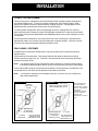
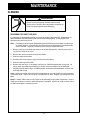
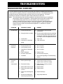
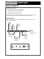
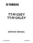
PRSM-96
PR Series
Positive Rotary Pumps
Models PR, PRE, and PRED
Service & Installation Manual
-2-
CONTENTS
Thank you for purchasing a Tri-Clover Product!
This manual contains disassembly and assembly instructions, maintenance procedures,
troubleshooting, and a complete parts list for all PR Series Pumps designed and manufactured by
Tri-Clover Inc., Kenosha, Wisconsin.
READ THIS MANUAL carefully to learn how to service these pumps. Failure to do so could result
in personal injury or equipment damage.
SAFETY
IMPORTANT SAFETY INFORMATION .................................................................................................... 4
INTRODUCTION
GENERAL INFORMATION ....................................................................................................................... 5
INSTALLATION
UNPACKING AND INSTALLATION .......................................................................................................... 6
PIPING HINTS ......................................................................................................................................... 8
MAINTENANCE
MAINTENANCE AND REPAIR ............................................................................................................... 12
ROTOR INSTALLATION ......................................................................................................................... 14
CLEANING AND INSPECTION .............................................................................................................. 15
TROUBLESHOOTING
TROUBLESHOOTING GUIDELINES ..................................................................................................... 17
PARTS LIST
ORDERING INFORMATION .................................................................................................................. 19
PR PUMP ............................................................................................................................................... 20
PRE & PRED PUMP .............................................................................................................................. 22
-3-
SAFETY
IMPORTANT SAFETY INFORMATION
Safety is very important!
DO NOT attempt to modify any Tri-Clover product. To do so could create unsafe conditions
and void all warranties. DO NOT place any Tri-Clover product in an application where
general product service ratings are exceeded.
The following DANGER, WARNING, AND CAUTION signs and their meanings are used within
these instructions.
! DANGER
Indicates an imminently hazardous situation which, if not
avoided, will result in death or serious injury. The word
Danger is used in the most extreme cases.
WARNING
Indicates a potentially hazardous situation which, if not
avoided, may result in minor or moderate injury. May
also be used to alert against an unsafe operating or
maintenance practice.
CAUTION
Indicates a potentially hazardous situation which, if not
avoided, could result in death or serious injury.
-4-
INTRODUCTION
GENERAL INFORMATION
GENERAL
This manual contains installation, operation, cleaning, and repair instructions, with parts list, for
PR, PRE, PRED pumps manufactured by Tri-Clover Inc. of Kenosha, Wisconsin. It also provides
a troubleshooting chart to aid in determining pump malfunctions.
WARNING
Before servicing pump, disconnect electrical
power source.
DESCRIPTION
The PR, PRE and PRED Series pump units are generally mounted on base plates which
accommodate the pump units and the drive motors.
The pump units are comprised of two sections, the pump frame section and the fluid head section.
The drive shaft and pump shaft with their respective o-rings, bearings, seal and retaining rings are
located in the inner pump frame section.
The timing gears are keyed to the shafts. Axial movement of the gears is kept to a minimum by
shaft shoulders and retaining rings.
Lip seals on the shafts and o-ring seals on the frame bores, prevent leakage of timing gear
lubricating oil into the pump bearing grease chamber.
Sealing of the fluid head along the shafts is accomplished by rotary seals, consisting of stationary
stainless steel seal rings with carbon inserts, stainless steel wear rings which are broached to fit
the shaft splines, and o-rings which seal off any pumpage.
An optional cover containing a pressure relief valve provides a positive means of protecting the
processing equipment and piping from excessive head pressures.
Rotors are available in two materials - rubber and metal. Rubber and metal rotors are available in
double and four lobe design.
The drive motors, used in conjunction with the PR, PRE and PRED Series Pumps are not covered
in this manual. Refer to the individual motor or drive manufacturer for service data.
-5-
INSTALLATION
UNPACKING AND INSTALLATION
UNPACKING EQUIPMENT
Check the contents and all wrapping when unpacking your equipment. Inspect all parts for
damage that may have occurred during shipping.
Note:
If the plastic pump port covers have been broken or disturbed in shipment,
dismantle fluid head to make sure it is free of all foreign materials before placing
pump in service.
Figure One
INITIAL LUBRICATION
Straightedge
The pump unit is lubricated at the factory prior to shipping and
will require no additional lubrication until after the pump is put
into service. When you receive the pump:
1. Remove the shipping plug from the top position in the gear
cover and install the vented plug shipped with the pump.
2. Check the oil level in the gear case. Oil should be even
with the plug opening marked with the "oil level" decal. If
oil is required, refer to the Maintenace and Repair section
on page 12 of this manual for details.
Flexible
Coupling
CORRECT ALIGNMENT
Figure Two
LOCATION
Straightedge
The pump unit should be located as near as possible to the
liquid source and in a position where the suction piping can be
short and direct with a minimum number of elbows and fittings.
It should also be readily accessible for inspection, cleaning
and lubrication.
Flexible
Coupling
FLEXIBLE COUPLINGS
Taper
Gauge
ANGULAR MISALIGNMENT
The purpose of a flexible coupling is to compensate for
temperature changes, and allow end movement of the pump
and motor shafts without interference with each other while
transmitting power from the motor to the pump. A flexible
coupling should not be used to compensate for shaft
misalignment.
Figure Three
Straightedge
When properly aligned, the flexible coupling should appear as
shown in the adjoining drawing. See Figure 1.
The faces of the coupling halves should be far enough apart
so that they do not touch each other when the motor shaft is
moved toward the pump.
Flexible
Coupling
PARALLEL MISALIGNMENT
The tools required for checking flexible coupling alignment are
a straightedge and taper gauge or set of feeler gauges. See Figures 2 and 3.
-6-
INSTALLATION
FLEXIBLE COUPLING ALIGNMENT
There are two types of misalignment encountered with flexible couplings, angular misalignment
and parallel misalignment. To check for angular misalignment, insert a taper gauge or feeler
gauge at four places located 90° apart around the coupling as shown. Coupling halves will be
aligned when the measurements are the same at all check points.
To check parallel misalignment, place a straightedge across the coupling half rims at the top,
bottom and both sides, making sure that the straightedge is parallel to the motor and pump shafts.
The coupling will be properly aligned when the straightedge rests evenly on the coupling rims at all
check points.
Correct alignment is obtained by use of shims under the motor mounting feet. Remember that
adjustments made in one direction may affect alignment in another direction. Therefore, several
checks of both angular and parallel alignment should be made.
SEAL FLUSHING - PRED PUMPS
All PRED Series Pumps have double-static o-ring product seals which must have flush liquid
applied to them.
Install seal flush as shown below. Use pressurized flush with products that tend to build up
between seal faces; latex, PVA, etc. Pressure in seal chamber should exceed pump discharge
pressure by at least 10 PSI.
Note:
Your Positive Rotary Pump is designed for either clockwise or counterclockwise rotation.
It should be noted that product flow will be in the same direction as the drive shaft rotation.
Connect the flexible coupling, start the pump and operate it until temperatures are stabilized. The
unit should then be shut down and the alignment immediately rechecked.
Note:
If corrections in alignment are necessary at this time, be sure to check in all directions
after making adjustments.
Figure Four
Figure Five
Seal flush liquid outlet to drain
adjust valve to give flow to drain
while maintaining flush pressure
Seal Flush
Liquid Outlet
to Drain
1
1
/8 "- 27 NPT
1
/ 4 Tubing
/4 " Tubing
Adjustable valve
to obtain liquid
flow to both seals
Seal Flush
Liquid Inlet
SEAL FLUSH PIPING
PRED PUMPS WITH
ATMOSPHERIC FLUSH
1
/8 - 27 NPT
Seal flush liquid inlet
adjust pressure to
SEAL FLUSH PIPING
exceed pump
discharge pressure PRED PUMPS WITH
PRESSURIZED FLUSH
-7-
Recommended Seal
Flush Flow Rate is
approximately 3 gallons
per hour. For elevated
temperature
applications, flow rate
must be sufficient to
maintain seal
temperature of 175°F or
less.
INSTALLATION
PIPING HINTS
GENERAL
This section provides some do’s and don'ts of piping which will aid in obtaining the maximum
efficiency and service from your pump.
•
Piping should be independently supported at both the suction inlet and discharge outlet.
•
Care should be taken that piping is properly aligned and does not put any strain on the pump
casing.
•
The piping should have as few bends as possible.
SUCTION PIPING
•
The suction piping should be short and follow a direct route with a minimum number of elbows
and fittings.
•
Elbows should not be used at the suction inlet as friction would be greatly increased, resulting
in head loss.
•
Excessive friction losses in the suction line could result in pump cavitation, causing poor
performance, noise, vibration, damage to equipment, and possible damage to product.
•
Whenever practical, the diameter of the piping at the suction inlet should be increased in size.
•
An eccentric tapered reducer should be used in lieu of a straight concentric tapered reducer to
prevent air pockets from forming and impairing pump efficiency. In turn, the eccentric reducer
may be placed at the inlet of the pump and should be positioned so the straight side is up.
•
Although positive displacement pumps are self-priming under moderate suction lift conditions,
a flooded suction is always preferable.
DISCHARGE PIPING
•
The discharge piping should be short and direct with a minimum number of elbows and
fittings. It is advisable to increase the pipe diameter at the discharge outlet to minimize head
loss.
PRESSURE RELIEF COVER ADJUSTMENT
Tri-Clover's relief cover is designed for added protection of the pump and other processing
equipment. The product flow will stop or is reduced when the head pressure on the discharge
side of the pump exceeds the pressure rating controlling the piston in the relief cover.
The relief cover is designed for use with either manual or pneumatic controls.
To adjust, install a line pressure gauge in the discharge line of the pump as close as possible to
the discharge port. Determine a maximum line pressure rating that is higher than the operating
pressure and adjust as follows:
-8-
INSTALLATION
Manual:
1. Loosen jam nut (09B-6).
2. Turn the adjusting screw (09-5A) (clockwise to increase pressure - counterclockwise to
decrease pressure) until the reading on the pump discharge line pressure gauge is the same
as the predetermined maximum line rating - then retighten jam nut (09B-6).
Pneumatic:*
When back pressure is regulated by pneumatic control, the spring inside the relief cover must be
removed prior to the operation. To remove spring it is necessary to remove relief cover parts in
the following sequence:
1. Jam nut (09B-6).
2. Clamp (13MON-X-S).
3. Cap nut (09B-3A).
4. Retaining ring (09B-13).
*
For PR300 replace cap nut (09B-3A), adjusting screw (09B-13) and jam nut (09B-6) with
R3-1-09D-3 cap.
Reassemble relief cover omitting retaining ring (09B-13) and spring (09B-4) and follow instructions
below for pneumatic operation:
1. Loosen jam nut (09B-6).
2. Turn the adjusting screw (09B-5A) counterclockwise until o-ring (09B-14) is slightly
compressed, then retighten jam nut (09B-6).
3. Adjust pressure control valve at the source of supply (air or CO2) until the reading of the
discharge line pressure gauge is the same as the predetermined maximum line pressure
rating.
-9-
MAINTENANCE
CLEANING
WARNING
Before servicing the pump, disconnect the electrical
power source, carefully relieve all pressure, and drain all
fluids from the pump and connected piping.
DISASSEMBLY OF PUMP FLUID HEAD
It is necessary to disassemble parts of your pump for cleaning and sanitizing. Disassemble as
described below after disconnecting the suction and discharge piping. If so equipped, also
disconnect the relief cover air line.
Note:
For added protection when disassembling pump fluid head, place all parts on rubber mat
or wooden platform. Extreme care must be exercised during assembly and disassembly
of the fluid head - especially in handling of the rotary seal parts and rotors.
1. Remove casing nuts and slide the casing cover off the casing studs. Carefully remove the oring from the inside of the cover.
2. Remove the rotors from the drive and pump shafts.
3. Slide the casing off the studs.
4. Carefully remove the casing o-rings from the rear of the casing.
5. Slide the seal rings off the shaft.
6. Remove the wear rings. If necessary use Puller No. R80-200 supplied with your pump. Do
not pry wear rings off with a screwdriver or similar tool as the flanges may be damaged.
Carefully remove shaft o-rings. On PRED models, with double seal assemblies, remove rear
seal rings and o-rings.
Seals: Inspect the carbon face of the seal ring and the wear ring seal surface for nicks, scratches
or excessive wear. Inspect all o-rings for cuts, abrasions or wear. Replace any damaged or worn
parts.
Rotors: Inspect rubber rotor for cuts, cracks or other damage to the rubber composition. Inspect
metal rotor carbons for cracks or wear and replace if damaged. Check fit of metal or rubber rotors
on shafts and replace if excessively loose.
- 10 -
MAINTENANCE
REASSEMBLY OF FLUID HEAD
Note:
Sequence of disassembly and assembly is the same for models PR, PRE and PRED
except where noted.
To reassemble the fluid head:
1. Lubricate shaft o-rings with silicone grease (Tri-Clover L1011B) and insert o-rings into grooves
on shafts.
2. On PRED models, insert rear seal o-rings into alignment locating ring.
3. Slide rear seal rings into place in alignment locating ring.
4. For all models slide wear rings into place onto the shafts.
5. Slide seal rings into place. DO NOT LUBRICATE SEAL FACES EXCEPT WITH CLEAR
WATER. USE OF SANITARY LUBRICANTS MAY DAMAGE CARBON. TANGS ON THE
SEAL RINGS MUST BE ALIGNED WITH SLOTS IN CASING. SEAL AND PUMP CASING
CAN BECOME PERMANENTLY DAMAGED IF TANGS ARE NOT PROPERLY ALIGNED.
6. Insert casing o-rings into place on back of casing.
7. Slide casing securely into place.
8. Slide rotors in place over splined shafts.
9. Insert cover o-ring.
10. Place front cover in position on studs.
11. Replace and tighten the casing nuts.
12. Reconnect the suction and discharge piping.
- 11 -
MAINTENANCE
MAINTENANCE AND REPAIR
Maintenance of the PR, PRE and PRED pumps includes frequent lubrication of the shaft bearings,
checking the oil level in the timing gear compartment, changing of oil at regular intervals, and
inspection of pump components.
LUBRICATION OF OUTBOARD AND INBOARD BALL BEARINGS
The bearings should be greased after every 100 operating hours, using a high quality grease such
as Mobile Temp #1. Old grease in the grease chamber should be periodically removed by
removing the cleanout hole cover and scraping out excess grease. Mixing of different brands of
grease should be avoided, to prevent possible chemical reactions between the brands, which
could damage the bearings. Greases containing vegetable or animal bases should not be used
because they can develop harmful acids. Also avoid using greases containing graphite, rosin, talc
and other impurities.
Note:
Be sure the lubrication fittings are wiped clean before greasing, to prevent dirt from being
forced into the bearings during greasing.
If your pump has been operated under extremely dusty or wet conditions for several months, or
has been idle for a long period of time, the bearings should be cleaned thoroughly with white
gasoline or kerosene and new grease applied. Refer to the applicable paragraph for disassembly,
cleaning and inspection procedures.
LUBRICATION OF TIMING GEARS
The timing gears are lubricated with SAE 20 oil. At regular intervals check the oil level by
removing the oil level plug. Oil should be even with the bottom of the plug opening.
Every 200 operating hours, remove drain plug and drain the timing gear chamber. Add new oil
until proper level is reached.
DISASSEMBLY
It is recommended that periodic inspection of all parts be made to prevent malfunction caused by
worn or broken parts. To accomplish this inspection, it is necessary to completely disassemble
the pump. Sequence of disassembly is the same for models PR, PRE and PRED.
Disassembly of the Casing and Rotor
1. Disconnect the suction and discharge piping. Also disconnect the water line to the shaft seal
flush assembly, if pump is so equipped.
2. Remove the four bolts securing the pump to the base plate.
Note:
If the pump is removed from the base plate, be sure that any shims used to level the
pump are fastened together by some suitable means, tagged and reinstalled at their
original location at time of reassembly.
Disconnect the flexible coupling half from the pump shaft.
3. Remove the coupling key from the shaft. Remove casing nuts and slide casing cover from
studs. Carefully remove casing cover o-ring.
4. Disassemble the relief cover, if used, by removing the jam nut, clamp, cap nut and gasket.
Remove the retaining ring and slide the adjusting screw spring and thrust washer from the
piston. Carefully remove the o-ring from the adjusting screw.
- 12 -
MAINTENANCE
5. Remove the piston from the relief cover and carefully remove the o-rings and PTFE sleeves
from the piston.
6. Slide off the drive shaft and pump shaft rotors.
7. Remove the casing and carefully remove the casing o-rings.
8. Slide the seal rings of the shafts and carefully remove wear rings. If necessary use Puller No.
R80-200. Do not pry off with a screwdriver or similar tool which may bend flange area of wear
ring.
Note:
Do not use a screwdriver or a pointed tool to remove seals and o-rings. The seals and
o-rings are precision parts and are easily damaged.
9. Remove the shaft o-ring by placing the thumb of one hand and forefinger across the diameter
of the o-ring and pressing it with a circular motion so that the o-ring projects from the groove.
With the forefinger of the other hand work the o-ring from the shaft groove.
10. Remove the vented plug and the oil level plug. Drain the oil from the timing gear case by
removing the drain plug. Remove the gear cover cap screws and the gear cover.
11. Carefully remove the gear cover gasket.
12. Press out the gear cover seal if replacement is necessary.
13. Remove the timing gear retaining ring (Part No. 98) from each shaft. On models PR300,
PRE300 and PRED300, bend back the tab on lockwasher (Part No. 69), and remove locknut
(Part No. 22) and lockwasher.
14. Use suitable pullers and remove the timing gears.
15. Remove the woodruff keys from shafts.
16. Remove the outboard bearing cover retaining rings.
17. Press each shaft and bearing assembly through the housing from the rotor end. If a press is
not available, a soft hammer or a block of wood can be used to drive the shaft from the
housing.
18. Remove the outboard bearing cover and o-ring. Push out the bearing cover seal if
replacement is required.
19. If it is necessary to remove the alignment locating rings, use a long punch to tap them from
the inside of the frame. Note the original positions of these rings. The grooves in the rings
must be carefully aligned with grease fittings at reassembly. Press the seal from the
alignment locating ring if replacement is necessary.
No further disassembly is recommended unless inspection shows that replacement of bearings or
shafts is required. If bearings are to be replaced, remove the bearing retaining ring. Using a
bearing puller or an arbor press, remove the damaged bearing from the shaft.
- 13 -
MAINTENANCE
ROTOR INSTALLATION
Your Tri-Clover pump will operate only if the rotors are
correctly installed. Therefore carefully follow the
installation procedure listed below.
Figure Six
2D
2P
TWO LOBE ROTORS
1. Install 2D rotor onto top shaft.
Note:
It doesn't matter whether top shaft is pump
shaft or drive shaft.
2. After installing 2D rotor, rotate shaft if necessary to
obtain spline relationship as shown in Figure 6.
3. Install 2P rotor on lower shaft. 2P rotor must be
installed as shown in Figure 6. Rotors must form a
"T" shape when properly installed with the tip of
one rotor opposite the concave hub areas of the
mating rotor.
Note:
Pump cannot be operated unless the
above procedure is followed. If rotors are
not installed as shown, the pump will jam
when started resulting in damage to the
rotor or shaft.
2P
2D
Part 2D - Center line of wide spline
teeth is on center line of rotor
lobes.
Part 2P - Center line of wide spline
teeth is at a 45° angle with
center line of rotor lobes.
Figure Six
1D
SINGLE LOBE ROTORS
1P
1. Install 1D rotor onto top shaft.
Note:
It doesn't matter whether top shaft is pump
shaft or drive shaft.
2. After installing 1D rotor, rotate shaft if necessary to
obtain spline relationship as shown in Figure 7.
3. Install 1P rotor on lower shaft. 1P rotor must be
installed as shown in Figure 7. Large lobe of one
rotor must be next to small diameter or hub of
mating rotor.
Note:
Pump cannot be operated unless the
above procedure is followed. If rotors are
not installed as shown, the pump will jam
when started resulting in damage to the
rotor or shaft.
- 14 -
1P
1D
Part 1D -Center line of wide spline teeth
is on center line of rotor lobes.
Part 1P - Center line of wide spline teeth
is at a 45° angle with center
line of rotor lobes.
MAINTENANCE
CLEANING AND INSPECTION
1. Remove cleanout hole cover, and remove any accumulation of grease from inside of the
grease chamber.
2. Inspect the pump frame, gear cover and casing for cracks or other damage that could impair
function of the pump.
3. Clean the outside of the frame, shaft, timing gears and bearing covers with a clean rag soaked
in white gasoline or kerosene, and flush all surfaces.
4. Flush the inside of the pump frame with white gasoline or kerosene to remove any harmful
material. Dry with compressed air or allow solvent to evaporate.
Note:
Clean rotor end of the shaft thoroughly after reassembly to remove any solvent that
could contaminate the process fluid.
5. Inspect the shafts carefully for nicks or scratches. Remove small nicks or scratches with a
fine file or emery cloth.
6. Examine the bearing covers and rotors for cracks or other signs of excessive wear.
7. Examine the keyslots in shafts and gears and woodruff keys for signs of wear. Keys must fit
tightly in key slots.
SEAL INSPECTION - SEAL RING
1. Inspect the carbon face of the seal ring and seal ring chamber for nicks and scratches on the
sealing surfaces.
2. Carefully inspect the wear ring for excessive wear.
3. Examine the bearing cover seal, alignment ring seals, and the gear cover seal for cracks,
nicks and excessive wear.
4. Inspect all o-rings for cuts, abrasions or other wear that can cause leakage.
5. Carefully examine the gear cover gasket and cleanout cover gasket for nicks, cuts, scratches
or excessive wear.
Parts showing excessive wear should be replaced.
REASSEMBLY
If it is necessary to replace the bearing cover seals or alignment ring seals, the new seal must be
installed with the spring loaded seal lip facing away from the bearings. The spring loaded seal lip
on the gear cover seal must face the gears.
If it is necessary to replace the bearings:
1. Press the bearings onto the shaft and install the bearing retainer ring (Part No. 102).
2. Install the inboard shaft retainer ring (Part No. 177) in the pump frame.
3. Place the outboard bearing cover seal, outboard bearing cover and outboard bearing cover oring on the shaft.
4. Stand the pump on the eight studs and start the shaft through the pump frame.
5. Press the shaft until the bearings are firmly seated*. Install the outboard bearing cover
retainer rings (Part No. 177). Lubricate the bearings.
*
These bearings are an easy fit, and will not require much force.
- 15 -
MAINTENANCE
6. Install the woodruff keys in the shaft keyslots and press the
timing gears onto the shafts.
Figure Eight
7. Carefully align the timing marks on the gears as shown in Figure
Eight.
Timing
Marks
8. Install the timing gear retaining rings (Part No. 98).
9. On Model PR300, PRE300 and PRED300 pumps, assemble
lockwasher (Part No. 69) and locknut (Part No. 22) on the shafts.
10. Tighten locknut firmly and lock in place by bending a tab into a
slot on the locknut.
11. Insert seal in gear cover, carefully fit the cover gasket to the
cover and secure the gear cover to the pump frame with the cap
screws.
12. Install the drain plug, fill the oil reservoir to the proper oil level
and install the vent plug and the oil level plug.
13. Assemble the cleanout cover to the pump frame.
Timing Gears and Marks
14. Install the alignment locating rings. Be sure to align the slots in these rings with the grease
fittings.
15. Install the shaft o-rings and the wear rings.
16. Slide the seal rings onto the shafts and carefully align the tangs of the seal rings with the slots
in the casing.
17. Assemble the casing o-rings and casing and slide into place.
Note:
The seal rings and pump casing can become permanently damaged if tangs are not
properly aligned. Do not lubricate seal faces. Carbon will be damaged if lubricated.
18. Install the rotors and place casing cover o-ring in casing cover groove. Secure the cover to
the casing with the casing nuts.
19. Assemble relief cover in the reverse order of disassembly.
20. Rotate the drive shaft. If the pump rotates smoothly and is not leaking oil, mount it on the
base, and connect the flexible coupling to the pump shaft.
21. Align the coupling according to instructions given under the Installation section of this manual.
IMPORTANT: Be sure the bearings have been lubricated and gear oil added before placing
the pump back in service.
22. Connect the suction and discharge piping, and the water line to the seal flush assembly.
23. Reset pressure relief valve as described in relief cover adjustment.
- 16 -
TROUBLESHOOTING
TROUBLESHOOTING GUIDELINES
Tri-Clover pumps are relatively maintenance free with the exception of sanitizing and lubrication.
Like any piece of machinery, however, occasional problems can arise. The troubleshooting chart
provides a means of determining and correcting most of your pump problems. The motor
manufacturer should be contacted for specific repair instructions on the motor.
Note:
The troubleshooting chart has been prepared on the basis that the pump as installed has
been properly suited to its application. Should problems arise where the remedies listed
in the troubleshooting chart do not cure the situation, pump cavitation may be the
problem. Symptoms of pump cavitation, such as noisy operation, insufficient discharge
and vibration, can result when a pump is not properly applied. If these conditions are
present, check the system and reevaluate the application. If assistance is required,
contact Tri-Clover.
PROBLEM
1. No discharge
PROBABLE CAUSE
REMEDY
a. Pump speed too slow.
a. Correct wrong or poor electrical
connections.
b. Wrong direction or rotation.
b. Reverse a three-phase motor by switching
any two of three power leads at the motor
or controller. Reverse a single phase motor
according to motor nameplate insturctions.
c.
c.
Closed valve.
d. Obstruction in discharge
Open valve.
d. Clear obstruction.
piping.
2. Insufficient
discharge
3. Excessive
a. Pump speed too slow.
a. See 1.a. above.
b. Valve partially closed.
b. See 1.c. above.
c.
c.
Obstruction in discharge
piping.
d. Rotor damaged.
d. Replace rotors.
e. Air leak in suction line.
e. Check suction line joints.
f.
f.
Cavitation
a. Motor speed too high.
See note at beginning of Troubleshooting
section.
a. Internal motor wiring is incorrect
power
consumption
See 1.d. above.
replace motor; check line voltage.
b. Rotors are binding.
b. Relieve strain on casing; replace
defective rotors.
c.
c.
Motor shaft is bent or worn.
Replace shaft.
d. Power frame shaft is bent
or worn.
d. Replace shaft.
e. Power frame bearings are
worn.
e. Replace bearings.
f.
f.
Excessive misalignment
between pump and driver.
- 17 -
Align pump and driver.
TROUBLESHOOTING
PROBLEM
4. Pump is noisy
5.
Excessive
vibraton
6. Pump leaks
PROBABLE CAUSE
REMEDY
a. Magnetic hum.
b. Motor bearings are worn.
c. Foreign matter is rotating
with impeller.
d. Rotors are binding.
e. Motor shaft is bent or worn.
f. Power frame shaft is bent
or worn.
g. Power frame bearings are
worn.
h. Excessive misalignment
between pump and driver.
i. Cavitation.
a. Consult motor manufacturer.
b. Replace bearings.
c. Remove casing and remove
foreign matter.
d. See 3.b. on the previous page.
e. See 3.c. on the previous page.
f. See 3.d. on the previous page.
a. Pump is not leveled properly.
b. Excessive misalignment
between pump and driver.
c. Rotors are damaged.
d. Piping is not supported.
e. Power frame shaft is bent
or worn.
f. Cavitation.
a. Level pump.
b. See 3.f. on the previous page.
a. Casing cover loose.
b. Damaged inlet or outlet
fittings.
c. Casing cover o-ring
defective.
d. Casing o-rings defective.
e. Mechanical seal worn or
defective.
a. Tighten casing nuts.
b. Replace casing.
- 18 -
g. See 3.e. on the previous page.
h. See 3.f. on the previous page.
i.
See note at beginning of Troubleshooting
section.
c. Replace rotors.
d. Support discharge and suction piping.
e. See 3.d. on the previous page.
f.
c.
See note at beginning of Troubleshooting
section.
Replace o-ring.
d. Replace o-rings.
e. Replace seal.
Click here to Order Parts
PARTS LIST
ORDERING INFORMATION
ORDERING REPAIR PARTS
All orders for repair parts must contain the following data.
1. Complete model number (located on nameplate).
2. Pump serial number (located on nameplate).
3. Description and part number from parts list.
The exploded views and accompanying parts lists in this section facilitate ordering repair parts
from the factory. All parts of the pumps are exploded and keyed to the parts list.
ORDERING IMPELLERS
When ordering impellers, the base number designates the impeller size. To order a pump
impeller, specify the following:
1
MODEL
SIZE
4
NUMBER
OF LOBES
2
R3
R10
R25
R60
R125
R300
BASELINE
PORT
2
4
6
smallest
available
port size
7
0000
00
00
0
0
0
0
ELASTOMER
U - Buna N
Y - Fluoroelastomer/
SFY
E - EPDM
3
IMPELLER
KEY NUMBER
6
This number will
always be 02
CLEARANCE
Rubber
Impellers
Only
C - Cold
H - Hot
5
DRIVE OR PUMP
S HAFT IMPELLER
(B I LOBE ONLY)
D - Drive Shaft
P - Pump Shaft
MODEL NUMBER EXAMPLE
1
2
3
4
5
6
7
R10 - 1½ - 02 - 2PH - U
- 19 -
- 20 -
80-2A
80-3A
80-1
80-4B
Pump Shaft for 06
PR300 Pump
02
86B
35A
35
90A
09
102
47
80-4B
16
177
02
80-1
80-2A
01
35
80-3A
06
177
102
96
86
47
35A
37
18
19
16
177
96
93
49
37A
12
16
102
94A
177
59A
133
46
73
96
98
59
18
12
18
175A
179
98
177
37A
94A
128
130
37
49
177
49
58A
175
58
59B
37A
37
46
69
94A
Drive Shaft And Components
for the PR300 Pump
22
Click here to Order Parts
PARTS LIST
PR PUMP
- 21 R3-1-37A-U
R3-1-37-CS
Drive Shaft
Bearing - Inboard
Bearing - Outboard
Frame
Locknut
Alignment, Locating Ring
12
16
18
19
22
35
35A Alignment Locating Ring O-Ring
37
Bearing Cover Outboard
R3-1-A35-316L
Front Cover
09
R3-1-06-316
Not available
R3-1-19-C
R3-1-16
R3-1-16
R3-1-12-316
R3-1-09-316
Not available
Pump Shaft
Impeller Carbon
08
Not available
Not available
Not available
Not available
06
Impeller 2 or 4 lobe Tri-Clover Metal
02
Not available
See Ordering Impelllers
Impeller 6 lobe Rubber (Buna N - Hot)
Impeller 2 or 4 lobe Rubber (Buna N)
Impeller 6 lobe Rubber (Buna N - Cold) See Ordering Impelllers
02
02
Casing, Tri-Clamp Ports 6" x 6"
01
02
Not available
Casing, Threaded Ports 6" x 6"
01
Not available
Not available
Model 25
Not available
Not available
Not available
Not available
Not available
Not available
R25M-3-01B-316
R25-3-01B-316
Not available
Not available
Not available
Not available
R25M-1½-01B-316
R25-1½-01B-316
Not available
Not available
Model 60
Not available
Not available
Not available
Not available
Not available
Not available
R60M-301BF-316
R60-3-01BF-316
Not available
Not available
R60M-2-01B-316
R60-2-01B-316
Not available
Not available
Not available
Not available
Model 125
Not available
Not available
Not available
Not available
Not available
Not available
R125M-3-01B-316
R125-3-01B-316
R125M-2½-01B-316
R125-2½-01B-316
Not available
Not available
Not available
Not available
Not available
Not available
Model 300
Not available
Not available
R300M-6-B01B-316
R300-6-B01B-316
R300M-4-01B-316
R300-4-01B-316
Not available
Not available
Not available
Not available
Not available
Not available
Not available
Not available
Not available
Not available
R10-1½-37-CS
R10-1½-35A-U
R10-1½-A35-316L
Not available
R10-1½-19-C
R10-1½-16
R10-1½-16
R10-1½-12-316
R10-1½-09-316
R10-1½-08
R10-1½-06-316
R25-1½-37-CS
R25-1½-35A-U
R25-1½-A35-316L
Not available
R25-1½-19-C
R25-1½-16
R25-1½-16
R25-1½-12-316
R25-1½-09-316
R25-1½-08
R25-1½-06-316
R60-2-37-CS
R60-2-37A
R60-2-A35-316L
Not available
R60-2-19-C
R60-2-18
R60-2-18
R60-2-12-316
R60-2-09-316
R60-2-08
R60-2-06-316
R60-2-37-CS
R60-2-37A
R125-2½-A35-316L
Not available
R60-2-19-C
R60-2-18
R125-2½-18
R125-2½-12-316
R60-2-09-316
R60-2-08
R125-2½-06-316
R300-4-37-CS
R300-4-37A-U
R300-4-A35-316L
R300-4-22
R300-4-19-C
R300-4-18
R300-4-16
R300-4-12-316
R300-4-09-316
R300-4-08
R300E-4-06-316
See Ordering Impelllers See Ordering Impelllers See Ordering Impelllers See Ordering Impelllers See Ordering Impelllers
See Ordering Impelllers See Ordering Impelllers See Ordering Impelllers See Ordering Impelllers See Ordering Impelllers
Not available
Not available
Not available
Not available
Not available
Not available
Not available
Casing, Tri-Clamp Ports 4" x 4"
Not available
Not available
Not available
Not available
Not available
Casing, Threaded Ports 4" x 4"
01
Not available
Not available
01
Casing, Tri-Clamp Ports 2½" x 2½"
01
Not available
R10M-1½-01B-316
01
Casing, Threaded Ports 2½" x 2½"
01
Not available
Not available
Casing, Threaded Ports 3" x 3"
Casing, Tri-Clamp Ports 2" x 2"
01
Not available
R10-1½-01B-316
Casing, Tri-Clamp Ports 3" x 3"
Casing, Threaded Ports 2" x 2"
01
Not available
R3M-1-01-316
Model 10
Not available
01
Casing, Tri-Clamp Ports 1½" x 1½"
01
Model 3
R3-1-01-316
01
Casing, Tri-Clamp® Ports 1" x 1"
Casing, Threaded Ports 1½" x 1½"
01
Casing, Threaded Ports 1" x 1"
01
PR Pump
Key Description
Click here to Order Parts
MS-105-58A
R3-1-59-S
Plug
58
58A Vented Plug
59
SC905H-SS
Not available
59B Cleanout Hole Screw
Lockwasher
Gear Cover Gasket
69
73
Gear Retainer Ring
98
R3-1-128
R3-1½-133
R3-1-175-C
SC912H-S
R3-1-177
R3-1-179
128 Tachometer Plug with Gasket
133 Grease Fitting
175 Gear Cover
175A Gear Cover Screw
177 Shaft Retainer Ring
179 Gear Cover Seal
R3-1-102
102 Bearing Retainer Ring
R3-1-98
R3-1-96
Timing Gear Key
96
R3-1-93
R3-1-94A
Alignment Pin
94A Timing Gear
93
R3-1-90B
R3-1-86A-S
86B Casing Nut
90A Casing Cover O-Ring (Buna N)
R3-1-86-S
R3-80-4A-U
Casing Stud
80-4B Casing O-Ring (Buna N)
86
R3-1-80-3A-U
R3-1-80-2
80-2 Seal Ring
80-3 Shaft O-RIng (Buna N)
R3-1-80-1-S
80-1 Wear Ring
R3-1-73
R3-1-59A
R3-1-47
59A Cleanout Hole Gasket
Cleanout Hole Cover
MS-105-58
Bearing Cover Seal
49
R3-1-47
Alignment Locating Ring Seal
R3-1-46
Coupling Key
47
R3-1-37A-U
Model 3
46
37A Bearing Cover O-Ring
Key Description
PR Pump (cont.)
R10-1½-179
R10-1½-177
SC1113H-S
R10-1½-175-C
R10-1½-133
R10-1½-128
R10-1½-102
R10-1½-98
R10-1½-96
R10-1½-94A
R25-1½-93
R10-1½-90B
R25-1½-86B-S
R10-1½-86-S
R10-1½-80-4B-U
R10-1½-80-3A-U
R10-1½--80-2A
R10-1½--80-1-S
R10-1½-73
Not available
SC905H-SS
R25-1½-59-A
R25-1½-59-S
2EBH-105-58A
2EBH-105-58
R10-1½-47
R10-1½-47
R10-1½-46
R10-1½-37A-U
Model 10
R25-1½-179
R25-1½-177
SC1316H-S
R25-1½-175-C
R25-1½-133
R3-1½-128
R25-1½-102
R25-1½-98
R25-1½-96
R25-1½-94A
R25-1½-93
R25-1½-90B
R25-1½-86B-S
R25-1½-86-S
R25-1½-80-4B-U
R25-1½-80-3A-U
R25-1½--80-2A
R25-1½-80-1-S
R25-1½-73
Not available
SC905H-SS
R25-1½-59-A
R25-1½-59-S
2EBH-105-58A
2EBH-105-58
R10-1½-49
R25-1½-47
R25-1½-46
R25-1½-37A-U
Model 25
R60-2-179
R60-2-177
SC1519H-S
R60-2-175-C
R25-1½-133
R3-1-128
R60-2-102
R60-2-98
R60-2-96
R60-2-94A
R60-2-93
R60-2-90B
R60-2-86B-S
R60-2-86-S
R60-2-80-4B-U
R60-2-80-3A-U
R60-2-80-2A
R60-2-80-1-S
R60-2-73
Not available
SC905H-SS
R60-2-59A
R60-2-59-S
2EBH-105-58A
2EBH-105-58
R60-2-47
R60-2-47
R60-2-46
R60-2-37A
Model 60
R60-2-179
R60-2-177
SC1519H-S
R60-2-175-C
R25-1½-133
R3-1-128
R125-2½-102
R60-2-98
R60-2-96
R60-2-94A
R60-2-93
R60-2-90B
R60-2-86B-S
R125-2½-86S
R60-2-80-4B-U
R60-2-80-3A-U
R60-2-80-2A
R60-2-80-1-S
R60-2-73
Not available
SC905H-SS
R60-2-59A
R60-2-59-S
2EBH-105-58A
2EBH-105-58
R60-2-47
R125-2½-47
R60-2-46
R60-2-37A
Model 125
R300-4-179
R300-4-177
SC1520H-S
R300-4-175-C
R25-1½-133
R3-1-128
R300-4-102
Not available
R300-4-96
R300-4-94A
R60-2-93
R300-4-90B-U
R300-4-86A-S
R300-4-86-S
R300-4-80-4B-U
R300-4-80-3A-U
R300-4-80-2
R300-4-80-1-S
R300-4-73
R300-4-69
SC905H-SS
R60-2-59A
R60-2-59-S
2EBH-105-58A
2EBH-105-58
R300-4-49
R300-4-47
R300-4-46
R300-4-37A-U
Model 300
Click here to Order Parts
- 22 -
80-3A
80-1
06
35A
102
47
02
01
80-5
16
177
80-1
80-3A
Pump Shaft for
PRE300 and PRED Pumps
80-5
80-4B
80-2
80-1
35
90A
80-2
80-3A
Mechanical Seals
PRED Pump
80-2
80-4B
80-4B
02
86B
09
80-4B
80-2
06
86
35A
35
96
102
47
37
18
19
16
177
177
49
37A
93
12
16
102
94A
177
98
58A
175
58
18
37A
37
46
59B
96
59
18
73
59A
133
96
46
12
175A
177
49
128
130
179
177
37A
98
94A
37
49
69
94A
Drive Shaft And Components
for the PRE300 and PRED300 Pumps
22
Click here to Order Parts
PARTS LIST
PRE & PRED PUMP
- 23 R3-1-37-CS
37
Bearing Cover Outboard
R3-1-37A-U
R10-1½-37-CS
R10-1½-35A-U
R10E-1½-A35-316L
R3E-1-A35-316L
Alignment, Locating Ring
35
35A Alignment Locating Ring O-Ring
R10-1½-19-C
R10-1½-16
R10-1½-16
R10E-1½-12-316
R10-1½-09-316
R10E-1½-08
R10E-1½-06-316
Not available
R3-1-19-C
R3-1-16
R3-1-16
R3E-1-12-316
Not available
Not available
Not available
Not available
Not available
Not available
R25M-3-01B-316
R25-3-01B-316
Not available
Not available
Not available
Not available
R25M-1½-01B-316
R25-1½-01B-316
Not available
Model 60
Not available
Not available
Not available
Not available
Not available
Not available
R60M-301BF-316
R60-3-01BF-316
Not available
Not available
R60M-2-01B-316
R60-2-01B-316
Not available
Not available
Not available
Not available
Model 125
Not available
Not available
Not available
Not available
Not available
Not available
R125M-3-01B-316
R125-3-01B-316
R125M-2½-01B-316
R125-2½-01B-316
Not available
Not available
Not available
Not available
Not available
Not available
Model 300
Not available
Not available
R300M-6-B01B-316
R300-6-B01B-316
R300M-4-01B-316
R300-4-01B-316
Not available
Not available
Not available
Not available
Not available
Not available
Not available
Not available
Not available
Not available
R25-1½-37-CS
R25-1½-35A-U
R25E-1½-A35-316L
Not available
R25-1½-19-C
R25-1½-16
R25-1½-16
R25E-1½-12-316
R25-1½-09-316
R25E-1½-08
R25E-1½-06-316
R60-2-37-CS
R60-2-37A
R60E-2-A35-316L
Not available
R60-2-19-C
R60-2-18
R60-2-18
R60E-2-12-316
R60-2-09-316
R60-2-08
R60E-2-06-316
R60-2-37-CS
R60-2-37A
R125E-2½-A35-316L
Not available
R60-2-19-C
R60-2-18
R125-2½-18
R125E-2½-12-316
R60-2-09-316
R60-2-08
R125E-2½-06-316
R300-4-37-CS
R300-4-37A-U
R300E-4-A35-316L
R300-4-22
R300-4-19-C
R300-4-18
R300-4-16
R300E-4-12-316
R300-4-09-316
R300-4-08
R300E-4-06-316
See Ordering Impelllers See Ordering Impelllers See Ordering Impelllers See Ordering Impelllers See Ordering Impelllers
Not available
Frame
Locknut
Bearing - Outboard
18
22
Bearing - Inboard
16
19
Drive Shaft
12
R3-1-09-316
Not available
Model 25
Not available
See Ordering Impelllers See Ordering Impelllers See Ordering Impelllers See Ordering Impelllers See Ordering Impelllers
Front Cover
R3E-1-06-316
Not available
Not available
Impeller Carbon
Not available
Not available
09
Not available
Not available
08
Casing, Tri-Clamp Ports 6" x 6"
01
Not available
Pump Shaft
Casing, Threaded Ports 6" x 6"
01
Not available
Not available
Not available
06
Casing, Tri-Clamp Ports 4" x 4"
01
Not available
Not available
Impeller 2 or 4 lobe Tri-Clover Metal
Casing, Threaded Ports 4" x 4"
01
Not available
Not available
Impeller 2 or 4 lobe Rubber (Buna N)
Casing, Tri-Clamp Ports 3" x 3"
01
Not available
Not available
02
Casing, Threaded Ports 3" x 3"
01
Not available
02
Casing, Tri-Clamp Ports 2½" x 2½"
01
Not available
Not available
Not available
Not available
Casing, Threaded Ports 2½" x 2½"
01
Not available
Not available
Not available
Casing, Tri-Clamp Ports 2" x 2"
01
R10-1½-01B-316
R10M-1½-01B-316
See Ordering Impelllers
Casing, Threaded Ports 2" x 2"
01
Not available
Not available
Impeller 6 lobe Rubber (Buna N - Cold) See Ordering Impelllers
Casing, Tri-Clamp Ports 1½" x 1½"
01
Not available
Impeller 6 lobe Rubber (Buna N - Hot)
Casing, Threaded Ports 1½" x 1½"
01
R3M-1-01-316
Model 10
Not available
02
Casing, Tri-Clamp Ports 1" x 1"
01
Model 3
R3-1-01-316
02
Casing, Threaded Ports 1" x 1"
01
PRE & PRED Pump
Key Description
Click here to Order Parts
Model 3
MS-105-58A
R3-1-59-S
Plug
58
58A Vented Plug
59
Lockwasher
Gear Cover Gasket
69
73
R3-1-93
93
R3-1-96
Timing Gear Key
Gear Retainer Ring
96
98
R3-1½-133
R3-1-175-C
SC912H-S
R3-1-177
R3-1-179
175 Gear Cover
175A Gear Cover Screw
177 Shaft Retainer Ring
179 Gear Cover Seal
R3-1-128
128 Tachometer Plug with Gasket
133 Grease Fitting
R3-1-102
102 Bearing Retainer Ring
R3-1-98
R3-1-94A
94A Timing Gear
Alignment Pin
R3-1-90B
90A Casing Cover O-Ring (Buna N)
86B Casing Nut
R3-1-86A-S
R3E-1-86
Casing Stud
86
80-4B Casing O-Ring (Buna N)
17-125-U
R3-80-4A-U
80-3 Shaft O-RIng (Buna N)
80-5 O-Ring (Buna)
R3E-1-80-2
R3-1-80-3A-U
80-2 Seal Ring
R3E-1-80-1-S
80-1 Wear Ring
R3-1-73
SC905H-SS
Not available
59B Cleanout Hole Screw
R3-1-59A
R3-1-47
59A Cleanout Hole Gasket
Cleanout Hole Cover
MS-105-58
Bearing Cover Seal
49
R3-1-47
Alignment Locating Ring Seal
47
R3-1-46
Coupling Key
R3-1-37A-U
46
37A Bearing Cover O-Ring
Key Description
PRE & PRED Pump (cont.)
Model 10
R10-1½-179
R10-1½-177
SC1113H-S
R10-1½-175-C
R10-1½-133
R10-1½-128
R10-1½-102
R10-1½-98
R10-1½-96
R10-1½-94A
R25-1½-93
R10-1½-90B
R25-1½-86B-S
R10E-1½-86-S
17-25-U
R10-1½-80-4B-U
R10-1½-80-3A-U
R10E-1½--80-2A
R10E-1½--80-1-S
R10-1½-73
Not available
SC905H-SS
R25-1½-59-A
R25-1½-59-S
2EBH-105-58A
2EBH-105-58
R10-1½-47
R10-1½-47
R10-1½-46
R10-1½-37A-U
Model 25
R25-1½-179
R25-1½-177
SC1316H-S
R25-1½-175-C
R25-1½-133
R3-1½-128
R25-1½-102
R25-1½-98
R25-1½-96
R25-1½-94A
R25-1½-93
R25-1½-90B
R25-1½-86B-S
R25E-1½-86-S
17-7-U
R25-1½-80-4B-U
R25-1½-80-3A-U
R25E-1½--80-2A
R25E-1½-80-1-S
R25-1½-73
Not available
SC905H-SS
R25-1½-59-A
R25-1½-59-S
2EBH-105-58A
2EBH-105-58
R10-1½-49
R25-1½-47
R25-1½-46
R25-1½-37A-U
R60-2-179
R60-2-177
SC1519H-S
R60-2-175-C
R25-1½-133
R3-1-128
R60-2-102
R60-2-98
R60-2-96
R60-2-94A
R60-2-93
R60-2-90B
R60-2-86B-S
R60E-2-86-S
R60-2-37A
R60-2-80-4B-U
R60-2-80-3A-U
R60E-2-80-2A
R60E-2-80-1-S
R60-2-73
Not available
SC905H-SS
R60-2-59A
R60-2-59-S
2EBH-105-58A
2EBH-105-58
R60-2-47
R60-2-47
R60-2-46
R60-2-37A
Model 60
R60-2-179
R60-2-177
SC1519H-S
R60-2-175-C
R25-1½-133
R3-1-128
R125-2½-102
R60-2-98
R60-2-96
R60-2-94A
R60-2-93
R60-2-90B
R60-2-86B-S
R125E-2½-86-S
R60-2-37A
R60-2-80-4B-U
R60-2-80-3A-U
R60E-2-80-2A
R60E-2-80-1-S
R60-2-73
Not available
SC905H-SS
R60-2-59A
R60-2-59-S
2EBH-105-58A
2EBH-105-58
R60-2-47
R125-2½-47
R60-2-46
R60-2-37A
Model 125
Model 300
R300-4-179
R300-4-177
SC1520H-S
R300-4-175-C
R25-1½-133
R3-1-128
R300-4-102
Not available
R300-4-96
R300-4-94A
R60-2-93
R300-4-90B-U
R300-4-86A-S
R300E-4-86-S
R300-4-37A-U
R300-4-80-4B-U
R300-4-80-3A-U
R300E-4-80-2
R300E-4-80-1-S
R300-4-73
R300-4-69
SC905H-SS
R60-2-59A
R60-2-59-S
2EBH-105-58A
2EBH-105-58
R300-4-49
R300-4-47
R300-4-46
R300-4-37A-U
Click here to Order Parts
Tri-Clover
manufactures
a complete line of
TRI-WELD® fittings
TRI-CLAMP® fittings
BEVEL SEAT fittings
POSITIVE PUMPS
CENTRIFUGAL PUMPS
AUTOMATIC Air Actuated VALVES
STAINLESS STEEL TUBING
AUTOMATED FLOW CONTROL SYSTEMS
Terms, Warranty Provisions, Notice of Claims and Limitation of Liability
Prices and all terms and conditions of sale are established
in current price sheets and are subject to change without notice.
All orders are subject to acceptance by Tri-Clover Inc. at its
Kenosha, Wisconsin or Distribution Center* offices only. No
assignment of the purchaser’s rights may be made without
consent of Tri-Clover Inc.
Each Tri-Clover item is warranted to be free from manufacturing defects for a period of one (1) year from the date of
shipment, providing it has been used as recommended and in
accordance with recognized piping practice, and providing it has
not been worn out due to severe service, such as encountered
under extremely corrosive or abrasive conditions.
This warranty is expressly in lieu of any other warranties, express or implied, including but not limited to, any
implied warranty of merchantability or fitness for a particular purpose.
All claims must be in writing and must be mailed or delivered
by purchaser within thirty (30) days after purchaser learns of the
facts upon which such claim is based. Any claim not made in
writing and within the time period specified above shall be
deemed waived.
Purchaser’s sole and exclusive remedy and Tri-Clover
Inc.’s maximum liability for claims arising hereunder or for
negligence for any and all losses and damages resulting
from any cause shall be either the repair or replacement of
defective items or, at Tri-Clover Inc.’s option, the refund of
the purchase price for such items. In no event, including in
the case of a claim for negligence, shall Tri-Clover be liable
for incidental or consequential damages including loss of
profits.
No person, including any representative, employee or agent
of Tri-Clover, is authorized to assume on behalf of Tri-Clover Inc.,
any liability or responsibility in addition to or different from that
described in this provision. Any and all representations, promises, warranties or statements that are in addition to or different
from the terms of this provision are of no force or effect.
*Distribution Centers in Union City, California and Memphis,
Tennessee
2.5M
361/371-96
Printed in Dec 1996