1
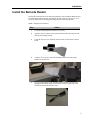
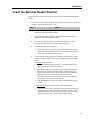
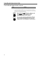
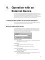
Title: ( BIO-RAD LOGO-B/W) Creator: Twister Barcode Reader Interface Guide P/N 400-0174 Copyright This document is published by Bio-Rad Laboratories. Copyright 1998 Bio-Rad Laboratories. All rights reserved. Reproduction in whole or part is prohibited. Trademarks The Bio-Rad logo is a registered trademark of Bio-Rad Laboratories. Twister is a trademark of Zymark Corporation. Microsoft is a registered trademark of Microsoft Corporation. Windows is a trademark of Microsoft Corporation. All other trademarks and registered trademarks are of their respective holders. Contents The information in this document may contain typographical errors or technical inaccuracies and is subject to change without notice. Modifications and additions may also be made to the products described in this document at any time. Statement of Proper Use The Twister is designed to be used in a laboratory environment. The Twister is integrated through hardware and software with an external microplate processing device, such as a reader, washer, or dispenser. The Twister automates the processing of microplates by the external device, providing increased walk-away time. The Twister software is designed to run under Windows 95 and Windows NT4.0. WARNING Use this product only in the manner described in this manual. When used other than as specified, the safety protections may be impaired. DANGER Risk of electric shock! TO REDUCE THE RISK OF ELECTRIC SHOCK, DO NOT REMOVE COVER. NO USER SERVICEABLE PARTS INSIDE. REFER TO QUALIFIED SERVICE PERSONNEL. Contact Us Bio-Rad Technical Services Department Open Monday–Friday, 8:00 a.m. to 4:00 p.m., Pacific Standard Time. Phone: (800) 424-6723, option 2, option 3 (510) 741-6576 Fax: (510) 741-5802 E-mail: [email protected] (U.S.) [email protected] (International) FCC NOTE This device complies with Part 15 of the FCC (United States Federal Communications Commission) Rules. Operation is subject to the following two conditions: This device may not cause harmful interference and must accept any interference received, including interference that may cause undesired operation. Changes or modifications to this equipment not expressly approved by the party responsible for compliance could void the user’s authority to operate the equipment. iii Table of Symbols DANGER These symbols are intended to draw your attention to particularly important information and alert you to the presence of hazards as indicated. Some of these symbols may not appear in the manual or on the product: An imminently hazardous situation, which, if not avoided, will result in death or serious injury. WARNING A potentially hazardous situation, which, if not avoided, could result in death or serious injury. NOTE A cautionary statement; operating tip, or maintenance suggestion, which may result in instrument damage if not followed. Hazardous voltage, risk of shock injury. Risk of body parts, hair, jewelry or clothing getting caught in a moving part. Risk of puncture injury. Risk of eye injury, wear safety glasses. Risk of fire. Risk of poison. Risk of explosion. iv Table of Symbols These symbols are intended to draw your attention to particularly important information and alert you to the presence of hazards as indicated. Some of these symbols may not appear in the manual or on the product: Hazardous fumes. Hot surface, risk of burns. Ground symbol. CE compliance mark. Output. Input. Signifies that the unit has passed safety tests for grounding, high voltage spikes and voltage leakage. F Helpful hints, additional information. Equipment Labels Equipment labels are color coded as follows: Yellow: Caution, risk of danger Red: Stop Blue: Mandatory action Green: Safe condition or information v Table of Contents 1. INTRODUCTION .............................................................................................1 PREINSTALLATION REQUIREMENTS.....................................................................................1 Tools Required ...............................................................................................................1 Twister Setup Required ..................................................................................................1 ASSEMBLY OVERVIEW .......................................................................................................1 2. INSTALLATION ..............................................................................................3 Installation Warnings ......................................................................................................3 Installation Notes ............................................................................................................3 UNPACK THE INTERFACE KIT ..............................................................................................4 PARTS LIST.......................................................................................................................4 INSTALL THE BARCODE READER .........................................................................................5 INSTALL THE BARCODE READER INTERFACE SOFTWARE ......................................................7 START THE TWISTER SOFTWARE .......................................................................................8 TEACH THE BARCODE READER POSITION ...........................................................................9 3. OPERATION WITH THE ULTRAMARK .......................................................11 LOADING THE MICROPLATES IN THE PROPER ORIENTATION ...............................................11 4. OPERATION WITH AN EXTERNAL DEVICE...............................................13 LOADING THE MICROPLATES IN THE PROPER ORIENTATION ...............................................13 BARCODE PARAMETERS SCREEN .....................................................................................13 CHOOSE THE BARCODE PARAMETERS ..............................................................................14 GLOSSARY .............................................................................................................15 INDEX ......................................................................................................................17 vii 1. Introduction The Twister/Barcode Reader Interface Kit enables the Twister to use a barcode reader to read and record the barcodes on each microplate in the run. The Barcode Reader Interface Kit includes a Symbol barcode reader (which attaches to the Lid Storage Platform) and the software necessary to set the barcode reading options in each run. Preinstallation Requirements Tools Required Phillips head screwdriver Standard screwdriver Twister Setup Required Lid Storage Platform (properly installed and configured) Twister software Version 2.0 or above Barcode Reader Interface software compatible with Twister software V2.0 or above Assembly Overview After the Twister has been installed and configured (following the instructions in the Twister User Guide), you are ready to install and configure the barcode reader. This guide includes the following procedures for unpacking and installing the Barcode Reader Interface Kit: Unpack the Interface Kit Install the Barcode Reader Install the Barcode Reader Interface Software Configure the Twister Software 1 2. Installation Installation Warnings WARNING • Turn the Twister power OFF before beginning these procedures. • Use only the tools listed in this manual to perform the steps described in the instructions. • Never perform any operation on the instrument in an environment where potentially damaging liquids or gases are present. • Do not loosen/tighten any screws or touch parts other than those specifically designated in the instructions. Doing so may cause misalignment and could void the instrument warranty. • Never force any component to fit if it will not do so easily. Installation Notes NOTE 3 Twister/Barcode Reader Interface Guide Unpack the Interface Kit Step Action 1 First, inspect the shipping carton for damage. 2 Remove all components from the shipping carton and verify that all parts are included. (See the Parts List below.) If any parts are missing, contact Bio-Rad. See Contact Us at the front of this manual for more information. 3 Retain the shipping carton and packing materials. If the contents should need to be returned for repair, use the original packing materials and shipping carton. If the shipping carton has been damaged in transit, it is particularly important to retain it for inspection by the carrier in case there has been damage to the contents. Parts List The Twister Barcode Reader Interface Kit includes the following items: Symbol LS 1220 Barcode Reader Mounting Bracket and Hardware Power Cable and Power Supply Manual Trigger and Cable 9-pin to 25-pin Barcode Reader communications cable 25-pin to 9-pin adapter cable Barcode Reader Interface Guide (this document) Barcode Reader Interface software disk Symbol LS1220 Product Reference Guide 4 Installation Install the Barcode Reader The barcode reader attaches to the Lid Storage Platform. The Lid Storage Platform must be installed and configured before installing the barcode reader. See the Twister User's Guide for instructions on installing and configuring the Lid Storage Platform. Tools: Phillips head screwdriver Step Action 1 Locate the mounting bracket and the four #4 screws. 2 Align the four screw holes on the bottom of the barcode reader with the four holes in the mounting bracket. 3 Using the four #4 screws, attach the barcode reader to the bracket as shown below. 4 Using the two #8 screws, attach the mounting bracket to the Lid Storage Platform as shown below. 5 One end of the barcode reader communications cable has a split cable for plugging in the manual trigger (shown below). Insert the 9-pin plug on this end into the back of the barcode reader. 5 Twister/Barcode Reader Interface Guide Install the Barcode Reader, Continued Step Action 6 The 25-pin end of the barcode reader communications cable has a socket for the power cable. Plug the power cable into this socket, as shown below. 7 Plug the 25-pin end of the barcode reader cable into the 25-pin end of the adapter cable. 8 Plug the other end of the adapter cable (9-pin) into port A on the back of the Twister. Then plug the power cable into an appropriate power source. (See the Symbol LS 1220 Product Reference Manual for power requirements.) 9 Plug the manual trigger cable into the split cable on the back of the barcode reader. 10 To test the reader, locate the "Set Defaults" barcode on page 6-2 of the Symbol LS 1220 Product Reference Manual. Hold this barcode in front of the reader, and press the manual trigger. Hold the page far enough away from the reader (i.e., behind the platform) so that you can scan the laser over the barcode until you hear a "beep." NOTE 11 6 If the test barcode does not scan, verify that all communications cables and power cords are securely plugged into the Twister, the computer, the device, and the barcode reader. Review the Symbol LS 1220 Product Reference Manual (included in this interface package) for other features and functions of the barcode reader. Installation Install the Barcode Reader Interface Software The Barcode Reader Interface software enables the Twister software to communicate with and control the barcode reader. Step Action 1 Turn ON the computer. Start Windows, if it is not already running. 2 Click the Windows Start button to display the Start Menu. 3 Select Settings, and then click on Control Panel to open the Control Panel Folder. 4 Double-click the Add/Remove Programs icon to display the Add/Remove Programs dialog box. 5 On the Install/Uninstall tab, click the Install button. 6 Insert disk #1 of the Barcode Reader Interface software into the computer’s 3.5” disk drive, and then click the Next button. 7 If the program a:\BarcodeEnable.exe (or b:\BarcodeEnable.exe if the 3.5-inch drive is drive B) is not found, click the Browse button to find the setup.exe file manually. 8 Click the Finish button to begin installing the Barcode Reader Interface software. 9 Follow the prompts to complete the software installation. 7 Twister/Barcode Reader Interface Guide Start the Twister Software Step Action 1 Switch ON the Twister. 2 Double-click the Twister V2.0 icon on the Windows desktop. OR Select the Bio-Rad Twister V2.0 program group from the Windows Start button, then click on Twister V2.0. The Twister software starts, the Twister Splash Screen is displayed, and the software attempts to communicate with the Twister. 3 The Twister checks all COM Ports and attempts to communicate with the Twister. If an error message is displayed, check that the Twister is plugged in and turned on. If the Twister has power (the green Power indicator light on the front of the Twister is lit), and communication still cannot be established, contact Bio-Rad for further assistance. See Contact Us at the front of this manual for more information. When the Twister software establishes communication with the Twister, the Twister Main Menu is displayed. 8 Installation Teach the Barcode Reader Position Before the barcode reader can be used, the Twister must be taught the Barcode Reader Position. F The barcodes on your plates should be the same size and in the same location on all the plates. Do not mix plate types or sizes. Step Action 1 From the Twister Main Menu, click the Positional Training button to display the Positional Training window. 2 In the Positional Training window, click the Barcode Reader button to display the Train Barcode Reader window. 3 Place one bar-coded microplate in the main Input rack on the Twister (Position 4) with the barcode facing the front of the Twister. 4 Click the OK button in the dialog box. F 5 The Twister moves to the Home position and initializes the barcode reader. The Twister arm then retrieves the microplate from position 4 and moves to the Barcode reader position. You can train the reader position either manually or automatically. (Note: Manual training will result in more precise alignment of the reader and the plates.) To manually train the position: a) Hold down the manual trigger button (i.e., the button attached to the cable) and note where the scan beam shines. b) Move the microplate up and down and left and right using the arrow buttons in the Train Barcode Reader window, and then trigger the barcode reader until the laser scans the barcode. The laser should be aligned with the center of the barcode. When the barcode is successfully scanned, the barcode reader will beep. Keep adjusting until the laser scans the center of the barcode. c) Click the OK button to display the settings in the Positional Training window. To automatically train the position, click the Auto Locate button. F The Twister will move the microplate slowly until the barcode reader reads the barcode, and then return the microplate to position 4. The Train Barcode Reader window will close and the rotary and vertical offsets will be displayed in the Positional Training window. 9 Twister/Barcode Reader Interface Guide Teach the Barcode Reader Position, Continued Step 10 Action 6 Save the settings and close the Positional Training window. 7 Click the Save Plate Data Button to save the current settings to the plate displayed in the Plate Description textbox. If the plate is the current default, the Twister will be updated automatically. NOTE You must now exit the Twister software and then restart it to download your new positional settings to the Twister. NOTE You are now ready to go back to the Twister User Guide and install either the Extended Capacity Kit or the Ultramark or other device. 3. Operation with the Ultramark The Barcode Reader, the Twister, and the Ultramark are all operated through Bio-Rad's Microplate Manager software, which is included with the Ultramark. When you perform a plate run, each barcode is scanned and recorded in a plate file in Microplate Manager. See the Microplate Manager User Guide for details. Loading the Microplates in the Proper Orientation When using the barcode reader with the Twister, the microplates must be loaded in the rack so the barcodes on the plates will face the barcode reader. 11 4. Operation with an External Device This chapter provides general information about operating the Barcode Reader with an external device other than the Ultramark. The Barcode Reader enables the Twister to read the barcode on each microplate and log the decoded barcodes in a log file in a userspecified location. Certain device interfaces may offer other options for using the decoded barcodes. See the interface guide for the specific device for available options. Loading the Microplates in the Proper Orientation When using the barcode reader with the Twister, the microplates must be loaded in the rack so the barcodes on the plates will face the barcode reader. Barcode Parameters Screen After the Barcode Reader Interface Kit is installed, the Barcode Parameters screen is displayed when setting the run options in the interface software for the specific device. The Barcode Parameters screen is typically displayed at the bottom of the Parameters Selection screen, but may appear in a different location. Log Barcodes checkbox When checked, the Twister reads the barcodes on each microplate and records the decoded barcodes in a text file. Log File Path The path and directory where the log file will be saved. Browse Button Opens the Browse dialog box to choose the log file path. Create New Log File Option When selected, the decoded barcodes are stored in a new log file and the previous log file is over-written. Append to Existing File Option When selected, the decoded barcodes from the run are added to the end of the log file, and previous data is not over-written. 13 Twister/Barcode Reader Interface Guide Choose the Barcode Parameters The Barcode Parameters screen is displayed in the Run Configuration window. Use this screen to read the barcode labels on the microplates in the run and record the barcodes in a log file. If barcode reading is not desired in a run, verify the Log Barcodes checkbox is not checked, and click the Next button at the bottom of the screen to display the next screen in the Run Configuration window. If barcode reading is desired: Step 14 Action 1 Click the Log Barcodes checkbox to select it. (The checkbox displays a check mark.) 2 In the Log File Path textbox, enter the desired path for the logging file OR Click the Browse button and select the desired directory. 3 Click the Create New Log File option to over-write the previous log file, or click the Append to Existing File option to add the new decoded barcodes to the end of an existing log file. 4 Click the Next button at the bottom of the screen to display the next screen in the Run Configuration window. Glossary Extended Capacity The Twister with the Expansion Kit has a capacity of up to 80 microplates without lids, or up to 60 microplates with lids. Toppers can be used on the microplates without lids. This configuration uses 5 racks (4 Input Racks and one Output Rack). Lid A flat cover placed on top of a microplate to prevent evaporation and/or contamination of the samples in the plate. Twister can process plates with a lid on each plate or with a lid only on the top plate in the stack. F When using a lid only on the top plate, the lower plates in the stack are protected by the plate above them. Rotary Home The Twister arm's furthest position of travel in a clockwise direction. Standard Capacity The standard capacity of the Twister is up to 20 microplates without lids, or up to 15 plates with lids. A topper can be used on the stack of 20 microplates. This configuration uses 2 storage racks (one Input Rack and one Output Rack). Storage Rack An aluminum rack used to store microplates. Topper A lid or an empty microplate placed on the top of a stack of microplates to prevent evaporation and/or contamination of the samples in the top plate. F When using a topper on the stack of microplates, the lower plates in the stack are protected by the plate above them. Vertical Home The Twister arm's highest vertical position. 15 Index A Append to Existing File Option........................ 10 Assembly Overview ........................................................ 2 B Barcode Parameters Choosing ...................................................... 11 Barcode Parameters Screen.............................. 10 Barcode Reader.................................................. 4 Barcode Reader Position Teaching......................................................... 7 C Choose the Barcode Parameters....................... 11 Communication Cable Barcode Reader.............................................. 4 Configure Twister Software ............................................ 6 Create New Log File Option ............................ 10 D Damage .............................................................. 3 I Installation Barcode Reader.............................................. 4 Barcode Reader Interface Software................ 5 Notes .............................................................. 1 Warnings ........................................................ 1 Introduction........................................................ 1 L Log Barcodes Checkbox .................................. 10 Log File Path Textbox...................................... 10 M Manual Trigger Cable ........................................ 4 Mounting Bracket............................................... 4 O Operation............................................................ 9 P Parts List ............................................................ 3 Power Cable ....................................................... 4 R Required Space .............................................................. 2 Tools .............................................................. 2 S Software Configuration ................................................. 6 Installation...................................................... 5 Starting ........................................................... 6 Space.................................................................. 2 Start the Twister Software.................................. 6 T Teach the Barcode Reader Position ................... 7 Tools .............................................................. 2, 4 Twister Software ................................................ 6 U Unpack the Interface Kit .................................... 3 Load the Microplates ......................................... 9 17


![TSQ Series Getting Started Guide Version C [FR]](http://vs1.manualzilla.com/store/data/006357565_1-ae930521dae4517a45cdbc191dde2ba3-150x150.png)