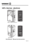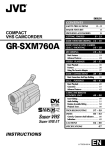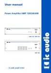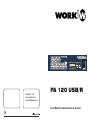
1
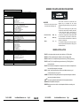
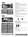
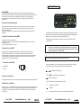
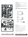
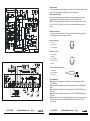
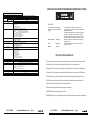
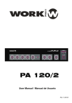
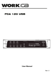
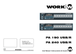
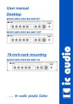
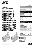
R
100 V LINE PUBLIC ADDRESS AMPLIFIER
-25 18-
BASS
TREBLE
AUX
CD
Digital MP3 Player Recorder
ON OFF
VOL
SD MMC
MIC 1
Equipson, S.A.
www.equipson.es
[email protected]
MIC 2
-160 - d0B
MASTER
MIC 3
MIC 4
REC
VOL
RPT SD USB
LINE
PA 120 USB/R
User Manual / Instrucciones de Usuario
POWER
PUBLIC ADDRESS AMPLIFIER
W/ USB-SD INTERFACE
AMPLIFICADOR DE MEGAFONIA
CON INTERFAZ USB-SD
ENGLISH
Page 1
ESPAÑOL
Página 9
This symbol on the product or on its packaging indicates that this product
shall not be trated as household waste. Instead it shall be handed over to
the applicable collection point for the recycling of electrical an electronic
equipment. By ensuring this product is disposed of correctly, you will help
prevent potential negative consequences for the environment and human
health, which could otherwise be caused by inappropriate waste handling
of this product. The recycling of amterials will help to conserve natural
resources. For more detailed information sabout recycling of this product,
please contact your local city office, your household waste disposal service
or the shop where you purchased the product.
Este símbolo en su equipo o embalaje, indica que el presente producto
no puede ser tratado como residuos domésticos normales, sino que deben
entregarse en el correspondiente punto de recogida de equipos electrónicos
y eléctricos. Asegurándose de que este producto es desechado
correctamente, Ud. está ayudando a prevenir las consecuencias negativas
para el medio ambiente y la salud humana que podrían derivarse de la
incorrecta manipulación de este producto. EL reciclaje de materiales
ayuda a conservar las reservas naturales. Para recibir más información,
sobre el reciclaje de este producto, contacte con su ayuntamiento, su
punto de recogida más cercano o el distribuidor donde adquirió el producto.
WARNING:THIS APPLIANCE MUST BE EARTHED
ESPECIFICACIONES TECNICAS
Tipo
Modelo
Alimentación
Bateria
Potencia
:
de Salida
Amplificador mezclador con interfaz USB/SD
PA 120 USB /R
AC115V / 230V , 50 / 60Hz ± 10% Conmutable
DC 24V (10% desviación max.)
Alimentación
:
Max
Típica
Salidas
Entradas
Frecuencia de Respuesta
Distorsión Armónica
Relación senal/ruido
Controles de Tono
Controles
Indicadores
Consumo de potencia AC
Consumo de potencia DC
Sirena
Prioridad
Dimensiones ( H×W ×D )
Peso
Color
Opciones de montaje
RISK OF ELECTRIC SHOCK
DO NOT OPEN
180W
120W
Salidas de Altavoz:
8 ohms Musica/Voz: ,100V
Voz:
100V
Tape output: 350mV 4.7KOhm
Pre output: 1V , 600 Ohms
MoH output: 8 Ohm 1W/ 600 Ohm ,1V balanceado.
Mic1/2:Ajust sens. (1mV~200mV),250 Ohms balanceado con phantom seleccionable.
,Balanceado sin phantom.
Mic3/4:Mic - 1mV, 250O
Phantom
- 1mV, 250 Ohm ,balanceado con alimentación phantom
Line
- 100mV, 47KOhm ,balanceado sin alimentación phantom
V
CD:500m ,47KOhm ,desbalanceado
Aux:200mV,47KOhm ,desbalanceado
TEL : 0.1~1V,600 Ohm ,ajustable, balanceado
Power in:1V,47KOhm ,desbalanceado
Mic1~Mic4: 60Hz ~ 15KHz ± 3dB
Aux/CD : 50Hz ~ 20KHz ± 3dB
TEL : 100Hz ~ 15KHz ± 3dB
Menos de 1% a 1KHz,potencia nominal
Todos los controles de volumen en sentido antihorario 80 dB por debajo de la potencia tipica
Mic1 ~ 4: 60dB por debajo de la potencia tipica
70dB por debajo de la potencia tipica
TEL :
Line
: (Aux/CD) 70dB por debajo de la potencia tipica
Graves :
± 10 dB a 100Hz
Agudos:
± 10 dB a 10KHz
Mic1~Mic4 control de volumen
Line(Aux/CD) control de volumen
Master control de volumen
TEL control de nivel de entrada
MOH control de nivel de salida
Controles de Tono (Graves,Agudos)
Conmutador de sirena on/off
Selector Line / phantom / mic
AC 115V / 230V Selector de red
Indicador de red (LED),Indicadores de nivel de salida (5 LEDS)
360 W
8A
Sirena de dos tonos (Senal
Ding/Dong precediendo una llamada)
Nivel de prioridad (Usando el conector DIN Mic1~4, )
Tel / Emer
Mic1 Mic2 Mic3 Mic4 Aux/C D
1 6
5 4
3 2
Nivel de prioridad (Usando el terminal de prioridad)
Tel / Emer Mic1 Mic2 Mic3 Mic4 Aux/CD
6
2 2
2 2 1
88 ×430 ×300 mm
Aprox 10 kg.
Negro
Sobremesa o rack 19”
IMPORTANT
The wires in the mains lead are coloured
in accordance with the following code:
Green and Yellow:
Earth
Blue:
Neutra (N)
Brown :
Live
(E)
(L)
As the colours of the wires in the mains lead of this
apparatus may not correspond with the coloured
markings identifying the terminals in your plug proceed as
follows:
The wire which is coloured green and yellow must be
connected to the terminal which is marked by the letter E
or by the safety earth symbol or coloured green and
. The wire which is coloured blue must be yellow
connected to the terminal which is marked with the letter
N or coloured black. The wire which is coloured brown
must be connected to the terminal which is marked with
the letter L or coloured red.
If a 13 Amp (B.S.1363) plug or any other type of plug is
used,a 5 Amp fuse must be fitted either in the plug or at
the distribution board.
GENERAL INSTALL ATION
DO NOT run microphone cables near mains, data, telephone or 100V line cables.
DO NOT run 100V line cables near data, telephone or other low voltage cables.
DO NOT exceed 90% of the amplifiers output power when using 100V line (speech only).
DO NOT exceed 70% of the amplifiers output power when using 100V line (high level
background music).
DO NOT use re-entrant horn loudspeakers for background music unless the loudspeaker has
been specifically designed for this purpose.
AVOID
jointing the microphone cable, when this is unavoidable make sure a good
screened connector is used, e.g. XLR.
ALWAYS use a balanced or floating low impedance microphone terminating into a balanced
input on long microphone cable runs.
ALWAYS use a mains grade double insulated cable for the loudspeaker cable runs.
ENSURE that all loudspeakers are in-phase.
ENSURE that there are no short circuits on the loudspeaker line before connecting to the
amplifier.
PA 120 USB/R
User Manual/Manual de uso
Pag 16
PA 120 USB/R
User Manual/Manual de uso
Pag 1
11
FRONT PANEL
8
7
12
13
6
9
R
100 V LINE PUBLIC ADDRESS AMPLIFIER
-25 18-
TREBLE
BASS
AUX
CD
Digital MP3 Player Recorder
ON OFF
VOL
REC
SD MMC
MIC 1
MIC 3
MIC 2
1
-160 - d0B
MASTER
MIC 4
3
2
4
RPT SD USB
POWER
10
5
7. Master Tone Control (Bass)
8. Master Tone Control (Treble)
9. Master Volume Control
10. Power On / Off switch
11. Power On / Off indicator LED
12. Output level indicator LED
13. USB/SD Interface
19
Baja Impedancia ( 8 ohms)
Esta salida permite la conexión de altavoces de baja impedancia, la carga mínima debe ser de 8 ohmios,
cuando dos o más altavoces deban ser conectados, asegúrese de que se conectan de forma que logre
los 8 ohmios necesarios.
Conectando un mezclador a un amplificador de potencia
Este amplificador puede ser conectado desde a la salida PRE out de un mezclador a la entrada Power In.
Pueden conectarse más amplificadores conectando la salida de uno a la entrada de otro. De esta manera
pueden conectase hasta 3 amplificadores.
Puerta de ruido VCA
El mezclador está equipado con un VOX en la sección master. El nivel de entrada que se requiere para
abrir la puerta de ruido de ajusta con el potenciómetro S601 situado en la placa frontal interna. Cuando
use la puerta de ruido, la relacion S/N será superior a 75 dB para entradas de MIC y 80 dB para entradas
Aux/CD.
REAR PANEL
18
Nota: Use sólo bafles de línea 100V.
La unidad dispone de dos salidas. La salida marcada como “Music/Speech”, lleva siempre la salida,
reproduciendo cualquier señal que entre en el amplificador. La salida marcada “Speech only”, reproduce
sólo una señal durante la condición de prioridad, así habrá una salida para esta conexión cuando el
micrófono esté en prioridad, esto significa que sólo la sirena y la señal procedente de uno de estos
micros estará presente en esta salida.
VOL
LINE
1. Mic1 Volume Control
2. Mic2 Volume Control
3. Mic3 Volume Control
4. Mic4 Volume Control
5. Line Volume Control
6. Aux / CD Selector Switch
Conexión de Altavoces
Configurando el Amplificador de potencia
20
21
22
23
24
PHANTOM
LINE
MIC
PHANTOM
LINE
MIC
25
26
28 29
27
230V~
115V~
1V 8
600
Apparatus delivered
Connected for 230v~
1W
+
P
+
COM
8
100V
SW401
PRE OUT
COM
100V
MIC 4
3
5
1. Earth Connection Screw
2. DC power supply terminals
3. Loudspeaker output terminals
4. Power input (RC A phono)
5. T ape output (2X RCA phono)
6. CD input (2X RC A phono)
7. Aux input (2X RCA phono)
8. Mic4 input (XLR-phone / balanced)
9. Mic4 input (DIN / balanced)
10. Mic3 input (XLR-phone / balanced)
11. Mic3 input (DIN / balanced)
12. Mic2 input (XLR / balanced)
13. Mic2 input Sens. control
14. Mic2 input (DIN / balanced)
15. Mic1 input (XLR / balanced)
PA 120 USB/R
SW404
1V
TEL/EMER
SENS VR
2
SW403
~
500mV
LINE FUSE
1
0
100mV
MONITOR OUTPUT
MUSIC/SPEECH
DC 24V
~
6
7
8
MIC 3
9
10
MIC 2
11
12
13
PAB-1
SENS VR
Configurando la sensibilidad de entrada
MIC 1
14
15
16
17
16. Mic1 input Sens. control
17. Mic1 input (DIN / balanced)
18. AC fuse holder
19. Mains voltage ( 115V/ 230V) selector switch
20. Mains input socket
21. Pre output (RCA phono)
22. Mic4 (Line/Phantom/Mic) selector switch.
23. Mic3 (Line/Phantom/Mic) selector switch.
24. Monitor output Level control
25. Monitor output terminals
26. Priority switch terminals
27. TEL/EMER input terminals
28. TEL/EMER input level control
29. Chime On/Off switch
User Manual/Manual de uso
Pag 2
El amplificador tiene 3 sensibilidades seleccionables ( 1V, 500 mV, 100 mV) localizadas en la placa (Sw401).
La sensibilidad por defecto es de 500m V.
Configurando en amplificador ( Conectando más amplificadores de potencia)
(Selector de modo localizado en la placa)
(SW403)
(SW404)
AMPLIFICADOR
STAND ALONE
MASTER
ESCLAVO
Funcionando una sola unidad
Para funcionamiento con una sola unidad, configure el selector Sw403, Sw404 ,localizados en la placa
en la posición “STAND ALONE”.
Funcionando hasta tres unidades
Para dos o 3 unidades, una de ellas debe ser designada como unidad Master. Todas las demás deben
ser conmutadas a modo “SLAVE” (esclavo)
PA 120 USB/R
User Manual/Manual de uso
Pag 15
USB/SD INTERFACE
Sirena ON/OFF
2. Dependiendo de la posición del conmutador “chime” situado en la parte trasera de la unidad, el
funcionamiento de las entradas MIC1-4 (Conector DIN), activará la sirena (Señal Ding-Dong, precediendo
una llamada). El volumen por defecto está configurado en 8 dB(40V). El valor es suficiente para
muchas aplicaciones. Si quiere alterar este valor, ajuste con el potenciómetro Vr303 situado en la
placa principal.
Digital MP3 Player / Recorder
VOL
Conexión de Teléfono/Emergencia
SD MMC
Esta entrada es para anuncios de emergencia y no se ve afectada por el control de volumen Master.
Este volumen puede ser configurado desde el control de volumen situado en el panel trasero (no
puede ser configurado a 0).
La entrada de emergencia tiene la prioridad más alta, todas las otras entradas tendrán menor rango
de prioridad.
Conexión de la salida de monitor (MOH)
Dos salidas de monitor en el panel trasero.
(I) 600 ohms/1V para alimentar el sistema EPABX. Nivel de salida ajustable. Consulte con el manual
del EPABX para su uso.
(II) 8 ohms, 1W para aplicaciones de monitor.
Conexión de Línea (Aux/CD)
El equipo dispone de una entrada auxiliar que puede ser usada para conectar otras fuentes de
señal como sintonizadores de radio, CD o Cassettes. Un mando ubicado en el panel frontal, le
permite seleccionar la fuente deseada. El control de nivel de línea funciona en cada entrada. Seleccione
la fuente musical que desea usando en conmutador y gire el mando “LINE” en sentido horario para
incrementar el valor o antihorario para disminuirlo.
REC
RPT
VOL
SD USB
This interface allows to play MP3 files from USB port or SD card slot. Changing the source only
pushing one button. The information is showed in the LCD display, allowing to navigate through
folders ans files. It incorporates volume control and REPEAT function.
The interface includes a recorder function, allowing to save the mixing information into SD
card or USB driver.
NOTE: It is only allows to do play or record application over one of USB/SD devices, by
this way, it is not possible to play a file from the USB port and to record the mix in
the SD card. So, first select the operation (PLAY or REC) and after select the source
where this application will occur (SD or USB).
NOTE: The maximum capacity of SD card or USB driver is 32 GB.
Conexiones conector RCA
One common application is to use the record fuction as message recording with microphone
into a SD card, being very easy to select the adequeate message and to play it.
Casquillo: Malla
Pin: Señal
CASQUILLO
To navigate between folders and files
PIN
VOL
Conexión de salida Tape
Conecte un previo o mesa al amplificador de potencia. Si se usa un compresor/limitador, ecualizador u otro
dispositivo externo, conecte el “PRE OUT” a la entrada del procesador externo y la salida del procesador
a “POWER IN”, en la cadena de la señal, “PRE OUT” va después del control de tonos y el control de
volumen master.
PA 120 USB/R
User Manual/Manual de uso
Pag 14
Allows to setup the volume of the played file
Switch on /off the interface
Este conector standard RCA, suministra una salida para la conexión de una pletina o grabador de cassette.
Entrada Power y Salida Pre
VOL
SD USB
Select the audio source (USB port or SD card slot)
RPT
Repeat function of played file
Play/Pause
REC
Record function. Allows to record the mix information into USB/SD device
PA 120 USB/R
User Manual/Manual de uso
Pag 3
Conexiones de red
El transformador de alimentación ha sido diseñado para su uso a 115V o 230V, seleccionable con el
conmutador situado en el panel trasero.
Conexión de la batería de 24V DC
+12V (50mA)
Cuando use baterías externas, conecte a tierra el amplificador mediante el terminal. La estabilidad
del sistema se incrementa con esta conexión.
NOTA: El cable de red debe de disponer de un fusible de fundido rápido ( 120W : 15A). Cuando
conecte las baterías, compruebe la polaridad.
SW
CHIME ON/OFF
CONTROL
VCA
CHIME SIGNAL
+VCC
Pre AMP
MIC1
MASTER
VOX
MUTE
Pre AMP
Conexión del micrófono
VOLUME
CONTROL
Las entrada MIC1-4 disponen de conector jack estéreo 1/4” balanceado y de conector XLR, situados
en el panel trasero ( con alimentación phantom seleccionable). Cablee los conectores de la siguiente
manera.
+VCC
LINK
Pre ANP
Pre AMP
MIC2
MUTE
LINE OUT
RELAY
PRIORITY
+VCC
SYSTEM
CONTROL
Pre OUT
100V
POWER IN
8OHM
Pre AMP
XLR (Funcionamiento Balanceado)
COM
MIC3
MUTE
PIN1: Malla
PIN2: Señal (vivo)
PIN3: Señal (retorno)
RECTIFIER
+VCC
TRANS.
FUSE
FUSE
Pre AMP
115V/230V
DC24V
MIC4
2
1
3
MUTE
600OHM
MOH DRIVER
DIN (Funcionamiento Balanceado)
COM
8OHM
Pre AMP
Pre AMP
AUX
TEL
PIN1: Señal (vivo)
PIN2: Masa
PIN3: Señal (retorno)
PIN4: Control de prioridad
PIN5: Masa
MUTE
CD
PA120/2 PRO
VOX
BUS
3
1
5
2
4
JACK 1/4” (Funcionamiento Balanceado)
GND
GND
Punta: Señal (vivo)
Aro: Señal (retorno)
Casquillo: Malla
Casquillo aro punta
115V~
230V~
600
Apparatus delivered
Connected for 230v~
PHANTOM
LINE
MIC
1V 8
1W
+
+
COM
8
100V
~
0
~
PHANTOM
LINE
MIC
MONITOR OUTPUT
MUSIC/SPEECH
DC 24V
P
TEL/EMER
Micrófono de prioridad
PRE OUT
COM
100V
LINE FUSE
MIC 4
MIC 3
SENS VR
SENS VR
MIC 2
MIC 1
MIC1 dispone de prioridad de palabra que se sobrepone a las señales de MIC2-4 y entrada de línea pero
NO a la entrada TEL/EMER.
MIC2 se sobrepone a las entradas MIC3-4 y Línea pero NO a la entrada TEL/EMER ni MIC1.
MIC3 se sobrepone a la entrada MIC4 y Línea pero NO a la entrada TEL/EMER ni MIC1, MIC2.
MIC4 se sobrepone a la entrada de Línea pero NO a la entrada TEL/EMER ni MIC1,MIC2, MIC3.
Las entradas MIC3,4 disponen de selector aliment. Phantom en el panel trasero. Las
entradas MIC1,2 se encuentran en la placa interna (SW401,SW402)
PA 120 USB/R
User Manual/Manual de uso
Pag 4
PA 120 USB/R
User Manual/Manual de uso
Pag 13
Mains Connection
The supply transformer has been designed for use on either 115Vac or 230 Vac, selected by slide
switch on rear panel. The amplifier is factory set at 230 Vac mains voltage.
+12V (50mA)
SW
CHIME ON/OFF
CONTROL
VCA
CHIME SIGNAL
+VCC
Battery Connection (24Vdc)
When using external batteries, earth the amplifier via the screw terminal because of the high
voltages present. Electrical stability of the system is increased by earthing the case.
NOTE: The connection cable must be fitted with an in-line fuse. quick blow type (30W : 5A, 60W :
8A, 120W : 15A, 240W : 20A, 480W : 40A). When Connecting batteries please ensure correct
.polarit y
Pre AMP
MIC1
MASTER
VOX
MUTE
Pre AMP
VOLUME
CONTROL
+VCC
LINK
Pre ANP
Pre AMP
MIC2
MUTE
LINE OUT
RELAY
PRIORITY
+VCC
SYSTEM
CONTROL
Pre OUT
100V
POWER IN
8OHM
Pre AMP
COM
MIC3
MUTE
RECTIFIER
+VCC
TRANS.
FUSE
FUSE
Pre AMP
Microphone Connection
Mic1~4 inputs are balanced standard 1/4” stereo jack, DIN and XLR Socket on the rear panel
(With selectable phantom power). Wiring is as follows:
115V/230V
DC24V
MIC4
MUTE
600OHM
MOH DRIVER
COM
8OHM
Pre AMP
Pre AMP
AUX
TEL
MUTE
CD
XLR (Balanced Operation)
Pin1 : Screen
2
Pin2 : Signal (live)
1
3
Pin3 : Signal (return)
PA120/2 PRO
VOX
BUS
DIN (Balanced operation)
Pin1 : Signal (live)
Pin2 : GND
Pin3 : Signal (Return)
3
Pin4 : Priority Control
1
5
Pin5 :GND
2
4
1/4” Stereo Jack Plug (Balanced operation)
GND
GND
Tip : Signal (live)
Ring : Signal (Return)
115V~
Sleeve : Screen
230V~
600
Apparatus delivered
Connected for 230v~
PHANTOM
LINE
MIC
1V 8
1W
+
P
~
DC 24V
+
COM
8
100V
~
PHANTOM
LINE
MIC
MONITOR OUTPUT
MUSIC/SPEECH
0
TEL/EMER
PRE OUT
COM
100V
LINE FUSE
MIC 4
MIC 3
SENS VR
SENS VR
MIC 2
MIC 1
MAX 6W X 20
PA 120 USB/R
User Manual/Manual de uso
Pag 12
Priority Microphone
Mic1 input has VOX priority which will override Mic2~4 and Line input signals but NOT the
TEL / EMER input.
Mic2 input which will override Mic3~4 and Line input signals but NOT the TEL/EMER and Mic1
Inputs.
Mic3 input which will override Mic4 and Line input Signals but NOT the TEL/EMER Mic1 and
Mic2 Inputs.
Mic4 input which will override Line input Signals only but NOT the TEL/EMER Mic1, Mic2, and
Mic3 Inputs.
Mic3~4 input are (DIN, phone / XLR) with Selectable phantom power located on the rear panel
and wire as above. Mic1~2 input are with Selectable phantom power located on the PCB
(sw401, sw402)
PA 120 USB/R
User Manual/Manual de uso
Pag 5
INTERFAZ USB/SD
Chime on/off
1. Switching the manual priority terminals on the rear panel will activate the chime function.
2. Depending on the position of the “chime” switch on the rear of the amplifier. switching on
Microphone 1~4 (DIN Socket) will activate the chime (Ding-Dong attention signal, preceding
a call). The default Volume of the chime is set at 8dB(40V). Which will be Sufficient in most
applications. If required the Volume Can be altered by adjusting the potention meter
(VR303, Chime) on the main PCB of the unit.
Digital MP3 Player / Recorder
VOL
Telephone/Emergency Connection
The emergency input is for emergency announcements / signals and is not affected by the
master volume control. The volume can be setted by the volume control on the rear panel
(can not be set to zero).
The emergency input has the highest priorit y , all other units will be overruled.
Monitor output (MOH) Connection
Two monitor outputs are provided on the rear panel.
(i) 600O / 1V. to feed an EPABX system. Output level adjustable. Please consult your EPABX
handbook to utilise this facilit y.
(ii) 8O, 1W for monitoring applications.
Line (Aux/CD) Connection
The equipment provides an auxiliary input which may be used for connecting other signal
sources such as a Radio Tuner, CD or Cassette player. A slide switch is located on the front
panel for selection of, Aux and CD. The line level Control operates on each of the input
sources. To ope rate select the desired music source using the slide switch and turn the “Line”
control clockwise to increase the volume or anticlockwise to reduce the volume.
The Aux / CD input sockets are standard RC A phono, two sockets are supplied and these are
linked together internall y, this allows stereo signal source to be used without the need to
obtain a special lead, however you may wish to check with the manufacturer of the signal
source to ensure that no damage will result if the left and right output channels are put in
parallel.
RC A Phono plug connections
SD MMC
REC
RPT
VOL
SD USB
Este interfaz permite ejecutar ficheros MP3 desde el puerto USB o el slot para tarjeta SD, cambiando
la fuente, simplemente pulsando un botón. La información es mostrada en la pantalla LCD, facilitando
la navegación entre carpetas y ficheros. Incorpora controles de volumen y función REPEAT.
El interfaz incluye función de grabación, permitiendo almacenar la información de la mezcla
en una tarjeta SD o un dispositivo USB.
NOTA: Sólo puede realizarse la aplicación de reproducción o grabación sobre uno de los
dispositivos, de esta manera no se puede ejecutar un fichero por el puerto USB y grabar
la mezcla en la tarjeta SD. Así, primero se selecciona la función a realizar (PLAY o REC),
y luego se selecciona la fuente donde va a tener lugar esa aplicación (SD o USB).
NOTA: La capacidad máxima de la tarjeta SD o el dispositivo USB a conectar es de 32 GB.
Una aplicación común es utilizar la función record para la grabación de mensajes con el micrófono
dentro de la tarjeta SD, siendo muy fácil seleccionar posteriormente el mensaje adecuado y
reproducirlo.
Sleeve- Screen
Pin- Signal
Para navegar entre carpetas y ficheros.
Tape Output Connection
These standard RC A phono sockets provide a mixed output suitable for connection to a tape or
Cassetter.recorde
VOL
Power in and pre out
Connects the mixer/preamplifier stage to the power amplifier stage. The connecting link must
be plugged in for normal operation as a mixer/amplifier. If a compressor/limiter, equalizer, or
other external signal processor is used in the sound system, connect the “PRE OUT ’ to the
SD USB
Selecciona la fuente de audio (USB port o slot para tarjeta SD)
RPT
Función REPEAT del fichero en ejecución.
input of the external processor and the output of the processor to “POWER IN” In the signal chain, “PRE
OUT” is after the tone controls and the master volume control.
PA 120 USB/R
User Manual/Manual de uso
Pag 6
VOL
Permite configurar el volumen del fichero en ejecución.
Pulsador para el encendido/apagado del interfaz.
Play/Pause
REC
Función grabación. Permite grabar la información de la mezcla en el dispositivo USB/SD.
PA 120 USB/R
User Manual/Manual de uso
Pag 11
11
PANEL FRONTAL
8
7
12
13
6
9
R
100 V LINE PUBLIC ADDRESS AMPLIFIER
-25 18-
TREBLE
BASS
AUX
CD
Digital MP3 Player Recorder
ON OFF
VOL
REC
SD MMC
MIC 1
MIC 3
MIC 2
1
-160 - d0B
MASTER
MIC 4
3
2
VOL
RPT SD USB
POWER
LINE
4
10
5
Control de volumen
1. Mic1
2. Mic2
Control de volumen
3. Mic3
Control de volumen
4. Mic4
Control de volumen
Control de volumen
5. Line
6.Selector CD/Aux
19
115V~
20
21
22
23
24
PHANTOM
LINE
MIC
PHANTOM
LINE
MIC
25
26
28 29
27
230V~
600
Apparatus delivered
Connected for 230v~
1V 8
1W
+
P
~
0
MONITOR OUTPUT
MUSIC/SPEECH
DC 24V
+
COM
8
100V
Low Impedance (8 Ohm )
This output allows connection of standard low impedance loudspeakers, the minimum load impedance
must be 8 Ohm, when two or more loudspeakers are use ensure that they are wired in such a way that the
load impedance is between 8 Ohm and 16 Ohm.
Connecting a Mixer Amplifier to a Power Amplifier
These amplifier can be connected using phono to phono leads from the mixer amplifier PRE out to the
power amplifier input phono socket. further power amplifier Can be connected by connecting from the
output of first power amplifier to the input of the second. up to three power amplifier can be connected in
this way.
If the Two Zone feature is required. the manual priority terminals must be used. connecting the priority
terminals from the mixer amplifier to the first power amplifier. up to three power amplifier can be
connected in this way.
7. Master Control de tonos(Graves)
8. Master Control de tonos (Agudos)
9. Master Control de volumen
10.Interruptor de red
11. LED indicador de red
12.LED indicador de nivel de salida
13. Interfaz USB/SD
PANEL TRASERO
18
Loudspeaker Connection
Note: Use only 100V Line Loudspeakers
Two loudspeaker outputs are provided. The output marked ‘Music/speech gives an output at all times,
reproducing any signal input into the amplifier. The output marked ‘Speech Only’ will only reproduce a
signal during a priority condition, therefore an output from this connection will be present when
Microphone is in a priority condition. this means that only the ‘Ding Dong’ chime and the signal from one
of these microphone inputs will be presented to this output.
VC A noise gate
The mixer amplifier are equipped with a VOX in master section. The input level which is required to
open the noise gate (S601 on the VR PCB-fixed on the front panel). When using the noise gate ( on )
then the S/N ratio can get more than 75dB for MIC inputs and 80dB for Aux / CD inputs.
Power amplifier setting
~
TEL/EMER
PRE OUT
COM
100V
SW403
SENS VR
LINE FUSE
SENS VR
100mV
500mV
MIC 4
MIC 3
MIC 2
SW404
1V
MIC 1
SW401
5
1.
2.
3.
4.
5.
6.
7.
8.
9.
10.
11.
12.
13.
14.
15.
Tornillo de conexión a tierra
Terminales de alimentación DC
Terminales de salida de altavoz
Entrada Power (RCA phono)
Salida Tape ( 2x RCA phono)
Entrada CD (2x RCA phono)
Entrada AUX (2x RCA phono)
Entrada MIC4 (XLR balanceado)
Entrada MIC4 (DIN balanceado)
Entrada MIC3 (XLR balanceado)
Entrada MIC3 (DIN balanceado)
Entrada MIC2 (XLR balanceado)
Entrada MIC2 Control sensibilidad
Entrada MIC2 (DIN balanceado)
Entrada MIC1 (XLR balanceado)
PA 120 USB/R
6
7
8
16.
17.
18.
19.
20.
21.
22.
23.
24.
25.
26.
27.
28.
29.
9
10
11
12
13
14
15
16
17
Entrada MIC1 Control sensibilidad
PAB-1
l
Input Sensitivity Setting
The amplifier has three ( 1V, 500mV, 100mV) Selectable input Sensitivity located on the PCB (SW401).
The sensitivity of amplifier are factory Set to 500m V.
l
Amplifier Settings (connecting more power amplifiers)
Entrada MIC1 (DIN balanceado)
Portafusible de red
Selector de red 115/220V
Conector de red
Salida Pre (RCA phono)
MIC4, selector Line/Phantom/Mic
MIC3, selector Line/Phantom/Mic
Control de nivel de salida de monitor
Terminales de salida de monitor
Terminales de prioridad
Terminales de entrada TEL/EMER
Control de nivel de entrada TEL/EMER
Conmut. On/off de la sirena
User Manual/Manual de uso
Pag 10
(mode selector switch located on the PCB)
(SW403)
(SW404)
(AMPLIFIER)
STAND ALONE
MASTER
SLAVE
Single unit operation
For single unit operation, set the mode selector switch (SW403,SW404) Located on the PCB to
the “ STAND ALONE”position.
Three unit operation
two or three unit operation, one unit must be designated the master unit, this can be done by
For
the mode selector switch to the “ MASTER “ position. All other units must be switched to “SL AVE”
mode.
PA 120 USB/R
User Manual/Manual de uso
Pag 7
ATENCION. ESTE PRODUCTO DEBE SER CONECTADO A TIERRA
Technical Specifications
Type
Model
Mains Voltage
Battery Voltage
Supply
Output
:
power
Public Address Mixer Amplifier w/ USB-SD interface
PA 120 USB /R
Max
Rated
:
RISK OF ELECTRIC SHOCK
DO NOT OPEN
AC 115V / 230V , 50 / 60Hz ± 10% Switchable
DC 24V (MAX 10% diviation)
Outputs
Inputs
Frequency response
Total harmonic distortion
Signal to noise ratio
Tone Controls
Controls
Indicators
AC power consumption
DC power consumption
Chime
Priority
Dimentions ( H ×W ×D )
Weight
Color
Mounting options
180W
120W
Speaker outputs:
Music/speech: 8 Ohm ,100V
Speech: 100V
Tape output: 350mV 4.7KOhm
Pre output: 1V, 600 Ohm
MoH output: 8 Ohm I wat t / 600 Ohm ,1V balanced.
Mic1/2:Sens. Adj (1mV~200mV),250 Ohm balanced with phantom power selectable.
Mic3/4:Mic - 1mV, 250Ohm ,balanced without phantom power.
Phantom
- 1mV, 250 Ohm ,balanced with phantom power.
Line
- 100mV, 47KOhm ,balanced without phantom power.
CD:500mV,47K Ohm ,unbalanced
Aux:200mV,47K Ohm ,unbalanced
TEL : 0.1~1V,600 Ohm, adjustable, balanced
Power in:1V ,47K Ohm ,unbalanced
Mic1~Mic4: 60Hz ~ 15KHz ± 3dB
Aux/CD : 50Hz ~ 20KHz ± 3dB
TEL : 100Hz ~ 15KHz ± 3dB
Less than1% at 1KHz,rated power
All Volume Controls C.C.W. : 80dB below rated power
Mic1 ~ 4: 60dB below rated power
TEL : 70dB below rated power
Line
: (Aux/CD) 70dB below rated power
Bass : ±10 dB at 100Hz
Treble: ±10 dB at 10KHz
Mic1~Mic4 volume control
Line(Aux/CD) volume control
Master volume control
TE L input level control
MOH output level control
Tone controls (Bass,Treble)
Chime on/off switch
Line / phantom / mic selector switch
AC 115V / 230V voltage Selector switch
Power indicator (LED),output level indicators (5 LEDS)
360 watts
8A
Two tone chime (Ding-done attention signal preceding a call).
Priority level (Using for Mic1~4, the 5 pole DIN connector)
Mic1 Mic2 Mic3 Mic4 Aux/C D
Tel / Emer
6
5 4
3 2
1
Priority level (Using for “priority” screw terminal)
Tel / Emer Mic1 Mic2 Mic3 Mic4 Aux/CD
6
2 2
2
2 1
88 ×430 ×300 mm
Approx 10 kg
Black
Table top or 19” rack mountable
IMPORTANTE
Los cables de alimentación están
coloreados de acuerdo al siguiente
código:
Verde - Amarillo:
Tierra (E)
Azul:
Neutro (N)
Marrón:
Fase (L)
Si los colores de los cables en el aparato, no se
corresponden con los marcados en el enchufe, proceda
de la siguiente manera:
El cable amarillo/verde debe ser conectado al terminal
marcado con la letra E. En cable coloreado en azul
debe ser conectado al terminal marcado con la letra N
o pintado de negro. El cableado coloreado en marrón
debe ser conectado al terminal marcado con la letra L
o pintado en rojo.
Si se usa un enchufe de 13 A, es conveniente el uso
de un fusible de 5 A.
INSTRUCCIONES GENERALES
NO utilice cables de micrófono cerca de alimentaciones de red, datos, teléfonos o líneas de 100V.
NO utilice líneas de 100V cerca de cables de datos, teléfono u otros de baja tensión.
NO exceda el 90% de la potencia de salida de los amplificadores cuando use línea 100V(Palabra).
NO exceda el 70% de la potencia de salida de los amplificadores cuando use línea 100V(Música).
UTILICE para música ambiente únicamente altavoces diseñados específicamente para ese uso.
VIGILE las conexiones de los cables como por ejemplo el apantallamiento de conectores XLR.
USE siempre micrófonos balanceados o de baja impedancia.
USE cable de doble aislante para hacer funcionar los altavoces.
ASEGURESE de que los altavoces están en fase
ASEGURESE de que no hay cortocircuitos en la línea de altavoces antes de conectar el amplificador.
PA 120 USB/R
User Manual/Manual de uso
Pag 8
PA 120 USB/R
User Manual/Manual de uso
Pag 9