1
Honeywell International Inc.
23500 W 105th Street
Olathe, KS 66061
U.S.A
CAGE: 22373
Telephone: (800) 601-3099 (U.S.A./Canada)
Telephone: (602) 365-3099 (International)
AV8OR Handheld
User’s Guide
Printed in U.S.A.
Pub. No. D200803000008
Revised March 2012
July 2008
Page T-1
© Honeywell International Inc. Do not copy without express permission of Honeywell
Honeywell Bendix/King AV8OR Handheld User’s Guide
Honeywell-Confidential
THIS COPYRIGHTED WORK AND ALL INFORMATION
ARE THE PROPERTY OF HONEYWELL
INTERNATIONAL INC., CONTAIN TRADE SECRETS
AND MAY NOT, IN WHOLE OR IN PART, BE USED,
DUPLICATED, OR DISCLOSED FOR ANY PURPOSE
WITHOUT PRIOR WRITTEN PERMISSION OF
HONEYWELL INTERNATIONAL INC. ALL RIGHTS
RESERVED.
Honeywell Materials License Agreement
The documents and information contained herein ("the
Materials") are the proprietary data of Honeywell
International Inc. and Honeywell Intellectual Properties Inc
(collectively "Honeywell"). These Materials are provided for
the exclusive use of Honeywell Service Centers;
Honeywell-authorized repair facilities; operators of
Honeywell aerospace products subject to an applicable
product support agreement, their wholly ownedsubsidiaries or a formally designated third party service
provider thereunder; and direct recipients of Materials from
Honeywell's Aerospace Technical Publication Distribution.
The terms and conditions of this License Agreement
govern your use of these Materials, except to the extent
that any terms and conditions of another applicable
agreement with Honeywell regarding the operation,
maintenance, or repair of Honeywell aerospace products
conflict with the terms and conditions of this License
Agreement, in which case the terms and conditions of the
other agreement will govern. However, this License
Agreement will govern in the event of a conflict between its
terms and conditions and those of a purchase order or
acknowledgement.
1. License Grant - If you are a party to an applicable product
support agreement, a Honeywell Service Center agreement, or
an authorized repair facility agreement, Honeywell hereby grants
you a limited, non-exclusive license to use these Materials to
operate, maintain, or repair Honeywell aerospace products only
in accordance with that agreement. If you are a direct recipient of
these Materials from Honeywell's Aerospace Technical
Publication Distribution and are not a party to an agreement
related to the operation, maintenance or repair of Honeywell
Title
Page T- 2
D200803000008
Rev 5 Mar 2012
© Honeywell International Inc. Do not copy without express permission of Honeywell
Honeywell Bendix/King AV8OR Handheld User’s Guide
aerospace products, Honeywell hereby grants you a limited, nonexclusive license to use these Materials to maintain or repair the
subject Honeywell aerospace products only at the facility to which
these Materials have been shipped ("the Licensed Facility").
Transfer of the Materials to another facility owned by you is
permitted only if the original Licensed Facility retains no copies of
the Materials and you provide prior written notice to Honeywell.
2. Rights In Materials - Honeywell retains all rights in these
Materials and in any copies thereof that are not expressly granted
to you, including all rights in patents, copyrights, trademarks, and
trade secrets. No license to use any Honeywell trademarks or
patents is granted under this License Agreement.
3. Confidentiality - You acknowledge that these Materials
contain information that is confidential and proprietary to
Honeywell. You agree to take all reasonable efforts to maintain
the confidentiality of these Materials.
4. Assignment And Transfer - This License Agreement may be
assigned to a formally designated service designee to the extent
allowed under an applicable product support agreement or
transferred to a subsequent owner or operator of an aircraft
containing the subject Honeywell aerospace products. However,
the recipient of any such assignment or transfer must assume all
of your obligations under this License Agreement. No assignment
or transfer shall relieve any party of any obligation that such party
then has hereunder.
5. Copies of Materials - Unless you have the express written
permission of Honeywell, you may not make or permit making of
copies of the Materials. Notwithstanding the foregoing, you may
make copies of only portions of the Material for your internal use.
You agree to return the Materials and any copies thereof to
Honeywell upon the request of Honeywell.
6. Term - This License Agreement is effective until terminated as
set forth herein. This License Agreement will terminate
immediately, without notice from Honeywell, if you fail to comply
with any provision of this License Agreement or will terminate
simultaneously with the termination or expiration of your
applicable product support agreement, authorized repair facility
agreement, or your formal designation as a third party service
provider. Upon termination of this License Agreement, you will
return these Materials to Honeywell without retaining any copies
and will have one of your authorized officers certify that all
Materials have been returned with no copies retained.
D200803000008
Rev 5 Mar 2012
© Honeywell International Inc. Do not copy without express permission of Honeywell
Title
Page T- 3
Honeywell Bendix/King AV8OR Handheld User’s Guide
7. Remedies - Honeywell reserves the right to pursue all
available remedies and damages resulting from a breach of this
License Agreement.
8. Limitation of Liability - Honeywell does not make any
representation regarding the use or sufficiency of the Materials.
THERE ARE NO OTHER WARRANTIES, WHETHER WRITTEN
OR ORAL, EXPRESS, IMPLIED OR STATUTORY, INCLUDING,
BUT NOT LIMITED TO, (i) WARRANTIES ARISING FROM
COURSE OF PERFORMANCE, DEALING, USAGE, OR TRADE,
WHICH ARE HEREBY EXPRESSLY DISCLAIMED, OR (ii)
WARRANTIES AGAINST INFRINGEMENT OF INTELLECTUAL
PROPERTY RIGHTS OF THIRD PARTIES, EVEN IF
HONEYWELL HAS BEEN ADVISED OF ANY SUCH
INFRINGEMENT. IN NO EVENT WILL HONEYWELL BE LIABLE
FOR ANY INCIDENTAL DAMAGES, CONSEQUENTIAL
DAMAGES, SPECIAL DAMAGES, INDIRECT DAMAGES, LOSS
OF PROFITS, LOSS OF REVENUES, OR LOSS OF USE, EVEN
IF INFORMED OF THE POSSIBILITY OF SUCH DAMAGES. TO
THE EXTENT PERMITTED BY APPLICABLE LAW, THESE
LIMITATIONS AND EXCLUSIONS WILL APPLY REGARDLESS
OF WHETHER LIABILITY ARISES FROM BREACH OF
CONTRACT, WARRANTY, TORT (INCLUDING BUT NOT
LIMITED TO NEGLIGENCE), BY OPERATION OF LAW, OR
OTHERWISE.
9. Controlling Law - This License shall be governed and
construed in accordance with the laws of the State of New York
without regard to the conflicts of laws provisions thereof. This
license sets forth the entire agreement between you and
Honeywell and may only be modified by a writing duly executed
by the duly authorized representatives of the parties.
Copyright - Notice
Copyright 2010, Honeywell International Inc. All rights reserved.
Honeywell is a registered trademark of Honeywell International Inc.
All other marks are owned by their respective companies.
Title
Page T- 4
D200803000008
Rev 5 Mar 2012
© Honeywell International Inc. Do not copy without express permission of Honeywell
Honeywell Bendix/King AV8OR Handheld User’s Guide
HONEYWELL CUSTOMER SUPPORT
For more information, including details regarding your warranty, visit
bendixking.com/av8or.
For technical support of this product please contact your local
Bendix/King Dealer. To locate the Bendix/King Dealer nearest you
visit bendixking.com/av8or.
For additional support, contact Honeywell Customer & Product
Support: at:
US & Canada:
1-877-712-2386
All other countries:
1-913-712-2613
Fax:
1-913-712-5697
HONEYWELL AEROSPACE TECHNICAL
PUBLICATIONS
If you have access to the Internet, go to the Honeywell Online
Technical Publications Web site at
https://portal.honeywell.com/wps/portal/aero to:
• Download or see publications online
• Make an order for a publication
• Tell Honeywell of a possible data error in a publication.
• If you do not have access to the Honeywell Online Technical
Publications web site and need technical publications information:
• Send an e-mail message to the complete customer care center
at:[email protected]
• Send a fax or speak to a person at the Customer and Product
Support contact numbers
D200803000008
Rev 5 Mar 2012
© Honeywell International Inc. Do not copy without express permission of Honeywell
Title
Page T- 5
Honeywell Bendix/King AV8OR Handheld User’s Guide
This Page
Intentionally Left Blank
Title
Page T- 6
D200803000008
Rev 5 Mar 2012
© Honeywell International Inc. Do not copy without express permission of Honeywell
Honeywell Bendix/King AV8OR Handheld User’s Guide
Revision History and Instructions
Manual:
AV8OR Handheld User’s Guide
Revision:
5 - Mar 2012
Summary
Revised hyperlinks in document.
D200803000008
Rev 5 Mar 2012
Record of Revisions
Page RR- 1
© Honeywell International Inc. Do not copy without express permission of Honeywell
Honeywell Bendix/King AV8OR Handheld User’s Guide
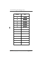
Record of Revisions
Record of Revisions
Page RR- 2
REVISION
NUMBER
REVISION
DATE
0
Jul, 2008
1
Sept,2008
2
Dec, 2008
3
Apr, 2009
4
Jan, 2011
5
Mar, 2012
D200803000008
Rev 5 Mar 2012
© Honeywell International Inc. Do not copy without express permission of Honeywell
Honeywell Bendix/King AV8OR Handheld User’s Guide
Table of Contents
1.
GETTING STARTED
Introduction
Unit Overview
Displays and Controls
Supplied software and Equipment
Optional Equipment
Charging the internal battery
Understanding Terms
Turning AV8OR on/off
AV8OR Sleep Mode
Turn Sleep Mode On and Off
Main Menu
Getting satellite signals
View GPS status from Settings
GPS Signal Strength
Current Position
GPS Data Flow
Satellite Acquisition Reset
1-1
1-1
1-2
1-3
1-5
1-6
1-7
1-8
1-9
1-10
1-10
1-10
1-11
1-11
1-12
1-12
1-13
1-13
2.
AVIATION MODE OPERATION
Basic Operation
Aviation Mode
Program Startup
Demo Mode
Aviation Main Menu Page
VFR Moving Map Function
Main Map Display Window
Fast Access
Image overlays
Map page Pointer/Non-Pointer:
Data Fields
VFR Moving Map Operation
Map Zooming
Map View
Smart Profile
Auto Zoom
Change View
Airports
Rnwys Tab
Comms Tab
2-1
2-1
2-1
2-1
2-4
2-5
2-10
2-10
2-12
2-13
2-16
2-18
2-25
2-25
2-26
2-26
2-27
2-29
2-31
2-32
2-34
D200803000008
Rev 5 Mar 2012
Table of Contents
Page TC-1
© Honeywell International Inc. Do not copy without express permission of Honeywell
Honeywell Bendix/King AV8OR Handheld User’s Guide
Table of Contents (cont)
Fuel Tab
Svcs Tab
Local Tab
NEAREST – Select Nearest Destination
Nearest Airports
Nearest VORs
Nearest User Wpts
Nearest Towns and Cities
Waypoint Alert
Turn Anticipation
DIRECT-TO Navigation
Create a Direct-To course from the Map
Create a Direct-To course from the keyboard entry
(No Flight Plan)
Re-center aircraft when Direct-To is already enabled
Bypass a WPT with a flight plan active
Enter a Direct-To WPT with a flight plan active.
PTR MENU
Create a User Waypoint
Center the Map around Pointer Position
PTR MENU – DIRECT-TO Navigation
To select a user defined point on the map:
PTR MENU – OBS Navigation
To select a NAVAID point on the map:
To select a user defined point on the map:
Center Map
Center To WPT/Center Aircraft
Selectable GPS Data Source
AUTONAV
STOP WATCH
Flight Plan Function
User WPTS
User Waypoint Icons
User Airport Entry
Creating New Flight Plan using the Virtual Keyboard
Inserting Victor Airways into Flight Plan
Smart Airways
Creating New Flight Plan using MAP Selections
Stored Flight Plans Processing
EDIT FPLAN
DATA VIEW Mode
Table of Contents
Page TC-2
2-34
2-36
2-36
2-37
2-39
2-41
2-41
2-42
2-43
2-44
2-45
2-45
2-46
2-48
2-49
2-50
2-52
2-52
2-54
2-55
2-56
2-56
2-56
2-57
2-58
2-58
2-59
2-60
2-61
2-62
2-62
2-64
2-65
2-66
2-70
2-72
2-73
2-77
2-78
2-78
D200803000008
Rev 5 Mar 2012
© Honeywell International Inc. Do not copy without express permission of Honeywell
Honeywell Bendix/King AV8OR Handheld User’s Guide
Table of Contents (cont)
MAP VIEW Mode
FPLAN ADMIN
COPY FPLAN
NEW FPLAN
INVERT FPLAN
DELETE FPLAN
FLY FPLAN
Active Flight Plan
Flight Logging
Text Format (Bendix/King) flight log
Jeppesen FliteStar flight log
Google Earth flight log
Memory Map flight log
Weather Function
Hardware Accessory
Receiving Weather Data
XM Weather Information Products
NEXRAD Composite Reflectivity (USA and Canada)
NEXRAD Legend
NEXRAD Map Setup
Graphical METARs (USA and Canada)
Graphical PIREPs (USA only)
Graphical AIRMETs (USA only)
Graphical SIGMETs (USA only)
Graphical Conv-SIGMETs (USA only)
Graphical Winds Aloft (USA only)
Graphical Winds Aloft Soft Keys
Winds Aloft Legend
Select Flight Level
Graphical Freezing Level
Text METARs (USA and Canada)
Text TAFs (USA and Canada)
Text PIREPs (USA only)
Text AIRMETs (USA only)
Text SIGMETs (USA only)
Text Conv-SIGMETs (USA only)
Legend
XM Overlays
Graphical Metar Overlay
Graphical TFR Overlay
Lightning Overlay
D200803000008
Rev 5 Mar 2012
2-79
2-79
2-80
2-80
2-80
2-81
2-82
2-83
2-84
2-84
2-85
2-85
2-85
2-86
2-86
2-86
2-88
2-90
2-90
2-91
2-93
2-95
2-97
2-100
2-102
2-104
2-105
2-105
2-106
2-107
2-108
2-109
2-110
2-111
2-112
2-113
2-114
2-115
2-116
2-116
2-118
Table of Contents
Page TC-3
© Honeywell International Inc. Do not copy without express permission of Honeywell
Honeywell Bendix/King AV8OR Handheld User’s Guide
Table of Contents (cont)
Cloud Top Overlay
Storm Cell Overlay
Traffic Function
Hardware Accessory
Traffic Main Page
Fields on The Traffic Page:
Traffic Setup
Flight Level
Enable/Disable Pop-UP
Taxiways FUNCTION
Chart View Page
Charts/Procedure Page
Select Charts to View Menu
PANEL FUNCTION
Panel Page
Auxiliary FUNCTION
Messages Page
Messages Soft Keys
Checklist
Wind Vector Calculator Page
Weight and Balance Page
Data Entry C.G. Graph
Layout
Profile
Envelope
Creating a new Weight and Balance Section
System Setup Function
System Setup Menu
General System Setup
Map Setup
Navigation Setup
Data Field Setup
Flight Plan Data Setup
Demo Mode Setup
Device Setup Page
Status Page
Refresh Mode
NMEA Output Setup
Transmit Default NMEA Sentences:
Transmit Selected NEMA Sentences
Table of Contents
Page TC-4
2-118
2-119
2-120
2-120
2-121
2-121
2-122
2-123
2-123
2-125
2-125
2-126
2-127
2-128
2-128
2-130
2-130
2-132
2-133
2-135
2-136
2-137
2-139
2-140
2-140
2-142
2-143
2-145
2-145
2-146
2-148
2-153
2-156
2-158
2-159
2-161
2-162
2-167
2-168
2-169
2-169
D200803000008
Rev 5 Mar 2012
© Honeywell International Inc. Do not copy without express permission of Honeywell
Honeywell Bendix/King AV8OR Handheld User’s Guide
Table of Contents (cont)
Shut Down
3.
2-171
AUTOMOTIVE MODE OPERATION
Warnings and Safety information
Map Updates
Glossary
Getting Started
Simple and Advanced modes
Soft Keys and Controls on the screen
Using keyboards
Additional Controls
Using the Map
Checking the Details of a Map Location
Manipulating the Map
Status Information and Hidden Controls on the Map
Using the Cursor (the selected map location)
Advanced Functions
Smart Zoom
Position Markers
Current GPS Position and Lock-on-Road
Returning to Normal Navigation
Selected Location (Cursor)
Original Position in the Cursor Menu
Daytime and night color schemes
Color scheme in tunnels
Route Calculation and Recalculation
Itinerary
Track Logs
Route demonstration
POI (Points of Interest)
Saving POI
Managing POI
Road Safety Cameras
Saving Road Safety Cameras
Camera Warning
Camera Types
Camera Directions
Speed limit warning
Advanced Features in GoDrive Version 8.3
ROUTE Navigation
Selecting the Destination of a Route
D200803000008
Rev 5 Mar 2012
3-1
3-1
3-2
3-2
3-4
3-6
3-8
3-10
3-11
3-13
3-13
3-14
3-17
3-23
3-24
3-24
3-25
3-25
3-26
3-26
3-27
3-27
3-27
3-28
3-28
3-30
3-31
3-31
3-32
3-32
3-32
3-33
3-33
3-33
3-35
3-36
3-37
3-38
3-38
Table of Contents
Page TC-5
© Honeywell International Inc. Do not copy without express permission of Honeywell
Honeywell Bendix/King AV8OR Handheld User’s Guide
Table of Contents (cont)
Selecting the Cursor as the destination ........................... 3-39
Entering an address or part of an address ...................... 3-39
Entering an Address (Europe) .........................................3-40
Entering an Address (North America, Australia) ............. 3-42
Entering an Address if house numbering is restarted ..... 3-44
Enter an Address without knowing the district/suburb .... 3-45
Selecting an Intersection as the Destination ................... 3-47
Selecting a City Center as the Destination ...................... 3-49
Entering an Address with a Postal Code ......................... 3-50
Tips on Entering Addresses Quickly ............................... 3-51
Selecting the destination from your Favorites ................. 3-52
Selecting the destination from the POIs ..........................3-52
Selecting the destination with saved POI search
criteria ..............................................................................3-54
Selecting the destination from the History .......................3-55
Selecting the destination by entering its coordinate ........ 3-55
Creating a Multi-point Route (Inserting a Via Point) ........... 3-56
Creating a Multi-point Route (Append a New
Destination) ........................................................................ 3-57
Editing the Route ................................................................ 3-58
Viewing Whole route on the Map (Fit to Screen) ............... 3-59
Watching the Simulation of the Route ................................ 3-59
Enabling Safety Mode ........................................................ 3-60
Pausing the Active Route ................................................... 3-60
Deleting the Next Via Point from the Route ....................... 3-60
Deleting the Active Route ................................................... 3-61
Using Track Logs ............................................................... 3-61
Recording the travelled path (creating a Track Log) ....... 3-61
Simulating a Track Log on the map ................................. 3-62
Changing the color of a Track Log ..................................3-62
Saving a Route ................................................................3-62
Loading a Saved Route ...................................................3-63
Reference book (Advanced mode) ....................................... 3-64
Map Screen ........................................................................ 3-65
Icons on the map .............................................................3-69
Battery, GPS Position Quality, Vehicle Type Indicator .... 3-70
Status Indicator Strip .......................................................3-72
Next two Route Events (Turn Preview fields) .................. 3-73
Objects on the map ............................................................ 3-74
Streets and Roads ...........................................................3-74
Elements of the Active Route ..........................................3-75
Table of Contents
Page TC-6
D200803000008
Rev 5 Mar 2012
© Honeywell International Inc. Do not copy without express permission of Honeywell
Honeywell Bendix/King AV8OR Handheld User’s Guide
Table of Contents (cont)
Detour menu .................................................................... 3-77
Cursor menu .................................................................... 3-77
Position menu .................................................................. 3-80
Route Information screen ................................................ 3-81
Trip Information screen.................................................... 3-84
Trip Computer screen ...................................................... 3-88
Quick menu...................................................................... 3-89
GPS data screen ............................................................. 3-91
Find menu ........................................................................ 3-94
Route menu ..................................................................... 3-95
Manage Menu .................................................................. 3-97
Manage Saved Routes ................................................. 3-97
Manage History ............................................................. 3-98
Manage Track Logs ...................................................... 3-98
Manage Favorites .......................................................... 3-100
Manage POIs .............................................................. 3-100
Manage Saved Search Criteria................................... 3-102
User Data Management .............................................. 3-103
Settings Menu ................................................................ 3-104
Map Screen Settings .................................................. 3-106
Sound Settings............................................................ 3-107
Route Planning Options .............................................. 3-108
Regional Settings ........................................................ 3-111
Navigation Settings ..................................................... 3-113
Warning Settings......................................................... 3-114
GPS Settings .............................................................. 3-116
Menu Settings ............................................................. 3-116
Device Settings ........................................................... 3-117
Track Log Settings ...................................................... 3-118
4.
MULTIMEDIA.......................................................................... 4-1
Music Player............................................................................ 4-1
Photos ..................................................................................... 4-2
Movie player ............................................................................ 4-3
Ebook Reader ......................................................................... 4-5
XM Tuner ................................................................................ 4-6
XM Weather and Radio Setup ............................................. 4-6
XM Radio Tuning.................................................................. 4-7
Downloading Multimedia Files ................................................ 4-8
5.
SYSTEM SETTINGS .............................................................. 5-1
D200803000008
Rev 5 Mar 2012
Table of Contents
Page TC-7
© Honeywell International Inc. Do not copy without express permission of Honeywell
Honeywell Bendix/King AV8OR Handheld User’s Guide
Table of Contents (cont)
GPS Status .............................................................................5-1
Backlight Brightness ............................................................... 5-1
Backlight control bar ............................................................. 5-2
Backlight shutdown setting ................................................... 5-2
Volume .................................................................................... 5-2
Enable/disable audio output ................................................. 5-3
Volume control bar ............................................................... 5-3
System Info .............................................................................5-3
Bluetooth ................................................................................. 5-4
Service Providers Page ..................................................... 5-7
DUN Setup Page ............................................................... 5-8
DUN Favorite Provider Selection Page ............................. 5-8
Initial Setup ........................................................................... 5-9
6.
APPENDIX .............................................................................. 6-1
Acronyms and Abbreviations .................................................. 6-1
Downloading/Uploading files from/To PC ............................... 6-4
Connection to An External GPS Source ................................. 6-7
Bendix/King KLN-94 ............................................................. 6-7
Garmin© GNS 430/430W/530/530W ................................... 6-7
Connection to An External Weather Source ........................... 6-9
Bendix/King KDR-610 Setup ................................................ 6-9
WxWorx XM Weather Receiver Serial Setup ..................... 6-11
WxWorx XM Weather Receiver Bluetooth Setup ............... 6-12
Connection to An External Traffic Source ............................. 6-16
Zaon XRX - Serial Setup .................................................... 6-16
Configuration of the Zaon XRX........................................6-16
Configuration of AV8OR ..................................................6-16
Zaon XRX - Bluetooth Setup .............................................. 6-17
External Flight Plans .............................................................6-17
Jeppesen FliteStar© PC Application .................................. 6-17
Subscriptions and Updates ...................................................6-18
Bendix/King Subscriptions:................................................. 6-18
GoFly Navigation Data Subscriptions .............................. 6-18
GoFly Fuel Pricing and Airport Services ......................... 6-19
Other Subscriptions: ........................................................... 6-19
GoFly Airport Diagrams: ..................................................6-19
GoFly XM Weather: .........................................................6-19
GoDrive Automotive Maps...............................................6-19
Updates: ............................................................................. 6-19
Table of Contents
Page TC-8
D200803000008
Rev 5 Mar 2012
© Honeywell International Inc. Do not copy without express permission of Honeywell
Honeywell Bendix/King AV8OR Handheld User’s Guide
List of Illustrations
Figure 1-2: AV8OR - Multimedia
1-1
Figure 1-3: AV8OR Controls
1-2
Figure 1-4: Charging with AV8OR turned off
1-7
Figure 1-5: Charge is completed
1-8
Figure 1-6: AV8OR Power Up
1-9
Figure 1-7: AV8OR Power off
1-10
Figure 1-8: AV8OR Sleep Mode
1-10
Figure 1-9: Main Menu
1-11
Figure 1-10: Settings Page
1-11
Figure 1-11: GPS Signal Strength Page – Locked and Unlocked1-12
Figure 1-12: GPS Information of Current position
1-12
Figure 1-13: GPS Data flow
1-13
Figure 1-14: GPS Reset
1-13
Figure 2-1: Initial Title Page
2-1
Figure 2-2: Self Test Failed
2-2
Figure 2-3: Self Test Failed Caution
2-2
Figure 2-4: SELF TEST COMPLETED Page
2-3
Figure 2-5: Final Title Page
2-3
Figure 2-6: Demo Mode
2-4
Figure 2-7: Map Page
2-5
Figure 2-8: Main Menu Page
2-5
Figure 2-9: Flight Plan – Flight Plan Index Page
2-6
Figure 2-10: Panel Page
2-6
Figure 2-11: Weather – Weather Map Page
2-7
Figure 2-12: Traffic Main Page
2-8
Figure 2-14: Messages – Messages Info Page
2-9
Figure 2-15: System Setup – System Setup Menu page
2-9
Figure 2-16: Main Map Display Page
2-10
Figure 2-17: Map – No position data CAUTION
2-12
Figure 2-18: Map – No Altitude Available CAUTION
2-12
Figure 2-19: Fast Access
2-13
Figure 2-20:Topo On Map - Overlay Setup
2-15
Figure 2-21: Map – Non-pointer Map mode
2-16
Figure 2-22: Map – Pointer Map mode
2-17
Figure 2-23: Map – Pointer Tag Window / Title Window
2-17
Figure 2-24: Map – Without soft keys
2-17
Figure 2-25: Map – Map View Setup
2-26
Figure 2-26: Map – Smart Profile On
2-27
Figure 2-27: Smart Profile – Airspace Vertical Boundaries
2-27
Figure 2-29: Auto Zoom Suspended
2-28
Figure 2-30: Map – Topo On
2-29
D200803000008
Rev 5 Mar 2012
Table of Contents
Page TC-9
© Honeywell International Inc. Do not copy without express permission of Honeywell
Honeywell Bendix/King AV8OR Handheld User’s Guide
List of Illustrations (cont)
Figure 2-31: Map – Relative Terrain
Figure 2-32: Map – Topo Off
Figure 2-33: Airport – MORE INFO
Figure 2-34: Airport – Rnwys Page
Figure 2-35: Airports – Extended Centerline on Map page
Figure 2-36: Airports – Deselect Runway
Figure 2-37: Airport – Comms Page
Figure 2-38: Airport – Fuel Page
Figure 2-39: Nearby Fuel Price Comparison
Figure 2-40: Airport – Svcs Page
Figure 2-41: Airport – Local Page
Figure 2-42: Map – Nearest Database Selection
Figure 2-43: Map – Direct-To OFF
Figure 2-44: Nearest Airports
Figure 2-45: Map – Airport Filter
Figure 2-46: Nearest VORs
Figure 2-47: Nearest User Waypoints
Figure 2-48: Nearest Towns and Cities
Figure 2-49: Waypoint Alert
Figure 2-50: Turn Anticipation
Figure 2-51: Map – Select a NAVAID
Figure 2-52: Map – Direct To a NAVAID
Figure 2-53: Map – Navigate to a NAVAID point
Figure 2-54: Map – Virtual Keyboard
Figure 2-55: Map – Entered Waypoint Info
Figure 2-56: Re-center aircraft – Step 1
Figure 2-57: Step 1 Bypass a WPT
Figure 2-58: Bypass a WPT – Step 2
Figure 2-59: Bypass a WPT – Step 3
Figure 2-60: Bypass a Waypoint Step 4
Figure 2-61: Enter a New WPT with Flight Plan Active
Figure 2-62: Enter New WPT – Select KEYBD Soft key
Figure 2-63: Enter New WPT Ident
Figure 2-64: New Direct-To Active.
Figure 2-65: Map –PTR MENU – Save Waypoint
Figure 2-66: Map – User Defined Waypoint
Figure 2-67: User Waypoint – MORE INFO
Figure 2-68: PTR Menu – Center to Map
Figure 2-69: Pointer Menu
Figure 2-70: Map Centered on Pointer
Figure 2-71: Map – Navigate to a user defined WPT
Table of Contents
Page TC-10
2-30
2-31
2-32
2-32
2-33
2-33
2-34
2-35
2-35
2-36
2-37
2-38
2-39
2-39
2-40
2-41
2-42
2-43
2-44
2-44
2-45
2-46
2-46
2-47
2-47
2-48
2-49
2-49
2-50
2-50
2-51
2-51
2-52
2-52
2-53
2-53
2-54
2-54
2-55
2-55
2-56
D200803000008
Rev 5 Mar 2012
© Honeywell International Inc. Do not copy without express permission of Honeywell
Honeywell Bendix/King AV8OR Handheld User’s Guide
List of Illustrations (cont)
Figure 2-72: OBS Course to NAVAID
2-56
Figure 2-73: Map –OBS Start
2-57
Figure 2-74: Map – OBS Navigation
2-57
Figure 2-75: Map – OBS Configuration
2-58
Figure 2-76: Map – Center to WPT
2-59
Figure 2-77: Map – Center Aircraft
2-59
Figure 2-78: Stop Watch Data Field
2-61
Figure 2-79: Flight Plan Index Page
2-62
Figure 2-80: Flight Plan – User Waypoint List
2-63
Figure 2-81: Flight Plan – New/Edit User Waypoint
2-63
Figure 2-82: Flight Plan – WPT Range and Bearing Config
2-64
Figure 2-83: Select User Waypoint Icon
2-64
Figure 2-84: User Airport Entry Page 1
2-65
Figure 2-85: User Airport Entry Page 2
2-65
Figure 2-86: Flight Plan – Index Page with no Flight Plan
2-66
Figure 2-87: New Flight Plan Page
2-67
Figure 2-88: Virtual Keyboard
2-67
Figure 2-89: Enter Waypoint Identifier
2-68
Figure 2-90: Waypoint Entry Window
2-68
Figure 2-91: All WPTs Entered into Flight Plan
2-69
Figure 2-92: Flight Plan Saved
2-69
Figure 2-93: Stored Flight Plan
2-70
Figure 2-94: Stored Plan
2-70
Figure 2-95: Select Airway Segment
2-71
Figure 2-96: Select Entry and Exit Points
2-71
Figure 2-97: Updated Flight Plan with Victor Airway
2-72
Figure 2-98: Smart Airways Entry Screen
2-72
Figure 2-99: Smart Airways - Segment Details
2-73
Figure 2-100: Flight Plan Index
2-74
Figure 2-101: New Flight Plan Page
2-74
Figure 2-102: Flight Plan – Map Selection of WPTs
2-75
Figure 2-103: Flight Plan – Waypoint Detail
2-75
Figure 2-104: Flight Plan – Selected Waypoint Detail Information2-76
Figure 2-105: Flight Plan – Stored Flight Plan with a Waypoint 2-76
Figure 2-106: Flight Plan – Save Waypoint
2-77
Figure 2-107: Flight Plan – Flight Plan Accepted
2-77
Figure 2-108: Flight Plan Index Page
2-78
Figure 2-109: Flight Plan – DATA VIEW
2-78
Figure 2-110: Flight Plan Selected WPT from Map
2-79
Figure 2-111: Flight Plan – FPLAN ADMIN
2-79
Figure 2-112: Flight Plan – COPY FPLAN
2-80
D200803000008
Rev 5 Mar 2012
Table of Contents
Page TC-11
© Honeywell International Inc. Do not copy without express permission of Honeywell
Honeywell Bendix/King AV8OR Handheld User’s Guide
List of Illustrations (cont)
Figure 2-113: Invert Flight Plan – Step 1
2-80
Figure 2-114: Invert Flight Plan – Step 2
2-81
Figure 2-115: Invert Flight Plan – Step 3
2-81
Figure 2-116: Delete Flight Plan
2-82
Figure 2-117: Flight Plan – FLY FPLAN
2-82
Figure 2-118: Flight Plan – Active Flight Plan
2-83
Figure 2-119: WX – No Data Received
2-88
Figure 2-120: WX – Non-pointer mode
2-88
Figure 2-121: WX – Choose Product
2-89
Figure 2-122: WX – NEXRAD with Cloud and Coverage Overlay2-90
Figure 2-123: NEXRAD Legend
2-91
Figure 2-124: WX NEXRAD Map – Overlay Setup
2-91
Figure 2-125: WX – NEXRAD & Storm Cells Overlay
2-92
Figure 2-126: Graphical TFRs
2-92
Figure 2-127: TFR Popup Window
2-93
Figure 2-128: TFR MORE INFO Window
2-93
Figure 2-129: WX – Graphical METARs
2-94
Figure 2-130: WX: – Graphical METARs Data Box
2-95
Figure 2-131: WX: – Text METARs Page
2-95
Figure 2-132: WX – Graphical PIREPs
2-96
Figure 2-133: WX – Graphical PIREPs Popup Window
2-96
Figure 2-134: WX – Graphical PIREPs Legend
2-97
Figure 2-135: WX – Text PIREPs
2-97
Figure 2-136: WX – AIRMETs
2-98
Figure 2-137:WX – Graphical AIRMET Popup Window
2-99
Figure 2-138:WX: – Graphical AIRMET LEGEND
2-99
Figure 2-139: WX – Text AIRMET Page
2-100
Figure 2-140: WX – Graphical SIGMETs
2-100
Figure 2-141: WX – Graphical SIGMET Popup Window
2-101
Figure 2-142: WX – Graphical SIGMET Legend
2-101
Figure 2-143: WX – Text SIGMETs
2-102
Figure 2-144: WX – Graphical Conv SIGMETs
2-102
Figure 2-145: WX – Graphical CONV SIGMET Popup
2-103
Figure 2-146: WX – Graphical Conv SIGMET Legend
2-103
Figure 2-147: WX – Text CONV SIGMETs Page
2-104
Figure 2-148: Graphical Winds Aloft
2-104
Figure 2-149: Graphical Winds Aloft – Speed and Direction
2-105
Figure 2-150: Winds Aloft Legend
2-106
Figure 2-151: Select Flight Level
2-106
Figure 2-152: Graphical Freezing Level Page
2-107
Figure 2-153: Freezing Level - Pointer Tag Window
2-107
Table of Contents
Page TC-12
D200803000008
Rev 5 Mar 2012
© Honeywell International Inc. Do not copy without express permission of Honeywell
Honeywell Bendix/King AV8OR Handheld User’s Guide
List of Illustrations (cont)
Figure 2-154: Freezing Level Legend
2-108
Figure 2-155: WX – Text METARs
2-108
Figure 2-156: WX – Text TAFs
2-109
Figure 2-157: WX –Text PIREPs
2-110
Figure 2-158: Text AIRMETs
2-111
Figure 2-159: Text SIGMETs
2-112
Figure 2-160: Text Conv-SIGMETs
2-113
Figure 2-161: WX – Pointer mode
2-114
Figure 2-162: WX – Legend Info
2-115
Figure 2-163: Topo On Map – Overlay Setup
2-115
Figure 2-164: Graphical Metar Overlay on Map Page
2-116
Figure 2-165: TFR Overlay
2-117
Figure 2-166: TFR Overlay – Popup
2-117
Figure 2-167: TFR Overlay – MORE INFO
2-118
Figure 2-168: Lightning Strikes on Map Page
2-118
Figure 2-169: Cloud Top Overlay on Nexrad Page
2-119
Figure 2-170: WX –Storm Cells Overlay on Nexrad Page
2-119
Figure 2-171: Traffic Main Page
2-121
Figure 2-172: Traffic Page – Traffic Setup
2-122
Figure 2-173: Traffic page – Enable Pop-Up
2-123
Figure 2-174: Traffic page – Disable Pop-Up
2-124
Figure 2-175: Chart View Page - No Airport Diagrams Loaded 2-125
Figure 2-176: Charts/Procedure Page
2-126
Figure 2-177: Chart View Page with Airport Selected Page
2-126
Figure 2-178: Chart View Page with Airport Selected Page
2-127
Figure 2-179: Messages
2-128
Figure 2-180: Panel Page: New Waypoint Selected
2-129
Figure 2-181: Messages
2-130
Figure 2-182: Checklist Page
2-134
Figure 2-183: Checklist Page
2-135
Figure 2-184; Wind Vector Calculation Page
2-135
Figure 2-185: Enter Magnetic Heading
2-136
Figure 2-186: Weight and Balance Page
2-137
Figure 2-187: W&B Data Entry Page with Profile and Envelope Tabs
Filled Out
2-138
Figure 2-188: W&B - FILE Options Page
2-138
Figure 2-189: W&B COG Graph with Profile and Envelope Tabs
Filled Out
2-139
Figure 2-190: W&B - Aircraft Loaded Beyond C.G. Limits
2-140
Figure 2-191: W&B Layout Page with Profile and Envelope Tabs
Filled Out
2-140
D200803000008
Rev 5 Mar 2012
Table of Contents
Page TC-13
© Honeywell International Inc. Do not copy without express permission of Honeywell
Honeywell Bendix/King AV8OR Handheld User’s Guide
List of Illustrations (cont)
Figure 2-192: W&B Profile Page
2-141
Figure 2-193: W&B Envelope Page
2-142
Figure 2-194: System Setup – System Setup Menu Page
2-145
Figure 2-195: System Setup – General System Setup Options 2-146
Figure 2-196: System Setup – Setting values
2-146
Figure 2-197: System Setup – Map System Setup Options
2-148
Figure 2-198: Map System Setup -- Select Map Layer
2-150
Figure 2-199: Map System Setup – Point Feature Setup
2-151
Figure 2-202: Map System Setup – Overlay Setup 1
2-152
Figure 2-203: System Setup – Navigation Setup
2-153
Figure 2-204: System Setup – Data Field Setup
2-156
Figure 2-205: System Setup – Wide windows Data Field
2-158
Figure 2-206: System Setup – Flight Plan Data Setup
2-158
Figure 2-207: System Setup – Demo Mode Setup
2-159
Figure 2-208: System Setup – Demo Mode Setup Ident Setting2-160
Figure 2-209: System Setup – Demo Mode Setup Ident Details2-160
Figure 2-210: System Setup – Device Setup Menu
2-161
Figure 2-211: System Setup – Status Page
2-162
Figure 2-212: System Setup – Internal GPS Status
2-163
Figure 2-213: System Setup – External GPS Status
2-163
Figure 2-214: System Setup – Common Map Data Sources
2-164
Figure 2-215: System Setup – Software and Database Version2-164
Figure 2-216: System Information Page
2-165
Figure 2-217: Traffic Status Page
2-165
Figure 2-218: System Setup – Weather Status Page
2-166
Figure 2-219: NMEA Output Setup Page
2-168
Figure 2-220: Exit Go Fly Warning Screen
2-171
Figure 2-221: Go Fly exit screen
2-171
Figure 3-1: AV8OR Main Menu
3-4
Figure 3-2: Simple Mode
3-5
Figure 3-3: Advanced Mode
3-5
Figure 3-4: Map Screen
3-13
Figure 3-5: Itinerary
3-29
Figure 3-6: Guidance Stripes
3-37
Figure 3-7: Highway Signposts
3-37
Figure 3-8: Enter an Address (Europe)
3-40
Figure 3-9: Find an Address – USA
3-42
Figure 3-10: Map Screen Advanced Mode
3-65
Figure 3-11: Route Information Screen
3-81
Figure 3-12: Trip Information Screen
3-84
Figure 3-13: Quick Menu
3-89
Table of Contents
Page TC-14
D200803000008
Rev 5 Mar 2012
© Honeywell International Inc. Do not copy without express permission of Honeywell
Honeywell Bendix/King AV8OR Handheld User’s Guide
List of Illustrations (cont)
Figure 3-14: GPS Status
Figure 3-15 Settings Menu
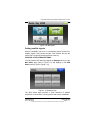
Figure 4-1: Multimedia Menu
Figure 4-2: Music Player – Searching for a Music File
Figure 4-3: Music Player – Playing Music
Figure 4-4: Photo Browser – Searching for a Photo
Figure 4-5: Photo Browser – Viewing a Photo
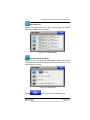
Figure 4-6: Movie Player – Searching for a Movie
Figure 4-7: Movie Player – Playing a Movie
Figure 4-8: EBook Reader – Searching for a Book
Figure 4-9: Ebook Reader
Figure 4-10: XM Radio Page
Figure 4-12: XM Categories Page
Figure 5-1: Settings Page
Figure 5-2: Backlight Page
Figure 5-3: Volume Control
Figure 5-4: System Info Screen
Figure 5-5: Bluetooth Manager Page
Figure 5-6: Bluetooth – Add Device Page
Figure 5-7: BlueTooth – Pair Device Page
Figure 5-8: Bluetooth – Passkey Requested Page
Figure 5-9: Bluetooth – Service Providers Page
Figure 5-10: Bluetooth – DUN Setup Page
Figure 5-11: Bluetooth – DUN Favorite Provider Page
Figure 5-12: Initial Setup Menu Page
Figure 6-1: Connection to USB port.
Figure 6-2: Configure AV8OR as external drive
Figure 6-3: External GPS Setup Screen
Figure 6-4: Weather Setup – KDR-610
Figure 6-5: WxWorx XM Weather Setup
Figure 6-6: WxWorx Bluetooth Receiver Setup
Figure 6-7: Bluetooth Manager Page
Figure 6-8: Add Bluetooth Device
Figure 6-9: BlueTooth – Pair Device
Figure 6-10: BlueTooth Passkey Required
Figure 6-11: BlueTooth Connecting
Figure 6-12: Bluetooth WxWorx Connection Established
Figure 6-15: Device Setup Page – Traffic
Figure 6-16: Navigation Data Subscription Coverage
Figure 6-17: AV8OR Handheld Upgrade Screen
D200803000008
Rev 5 Mar 2012
3-92
3-104
4-1
4-2
4-2
4-3
4-3
4-4
4-4
4-5
4-5
4-6
4-8
5-1
5-2
5-3
5-4
5-4
5-5
5-6
5-7
5-7
5-8
5-9
5-9
6-4
6-5
6-8
6-9
6-11
6-12
6-13
6-13
6-14
6-14
6-15
6-15
6-17
6-18
6-20
Table of Contents
Page TC-15
© Honeywell International Inc. Do not copy without express permission of Honeywell
Honeywell Bendix/King AV8OR Handheld User’s Guide
List of Tables
Table 1-1 Displays and Controls
Table 1-3 Optional Equipment
Table 1-4: Battery Charge Level
Table 2-1: Image Overlays on Primary Maps
Table 2-2 Course Deviation Limits
Table 2-3 Calculated Time En Route
Table 2-4 Time Zones
Table 2-5 Relative Terrain
Table 2-6 Graphical AIRMET Types
Table 2-7 Messages
Table 3-1: Simple Mode versus Advanced Mode
Table 3-2: Soft keys and controls on the screen
Table 3-3: Using Keyboards
Table 3-4: Additional Controls
Table 3-5: Controls to manipulate the Map
Table 3-6: Itenerary Screen
Table 3-7: Road Safety Cameras
Table 3-8: Navigation Menu
Table 6-1 Directory Structure
Table 6-2 KLN 94 Pinouts
Table 6-3 GNS 430/430W/530/530W Pinouts
Table 6-4 KDR 610 Pinouts
Table of Contents
Page TC-16
1-3
1-6
1-7
2-14
2-19
2-20
2-23
2-30
2-98
2-130
3-6
3-8
3-10
3-11
3-14
3-29
3-34
3-64
6-5
6-8
6-8
6-10
D200803000008
Rev 5 Mar 2012
© Honeywell International Inc. Do not copy without express permission of Honeywell
Honeywell Bendix/King AV8OR Handheld User’s Guide
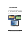
1.
GETTING STARTED
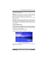
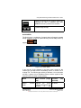
INTRODUCTION
Thank you for choosing the Honeywell AV8OR Handheld, a MultiFunction Display (MFD) that integrates a GPS, Navigation Database,
Graphical Terrain, Traffic and XM Weather/Radio into a single, easy
to use, portable aviation device. In addition to the benefits for
aviation use, this device also contains a complete compliment of
automotive navigation and multi-media features for use when not in
your aircraft. To get the most out of your new navigation system,
read this manual completely to learn the features for your unit.
Figure 1-1: AV8OR - In the Air or On the Ground
Figure 1-2: AV8OR - Multimedia
D200803000008
Rev 5 Mar 2012
Getting Started
Page 1-1
© Honeywell International Inc. Do not copy without express permission of Honeywell
Honeywell Bendix/King AV8OR Handheld User’s Guide
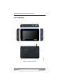
UNIT OVERVIEW
Figure 1-3: AV8OR Controls
Getting Started
Page 1-2
D200803000008
Rev 5 Mar 2012
© Honeywell International Inc. Do not copy without express permission of Honeywell
Honeywell Bendix/King AV8OR Handheld User’s Guide
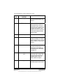
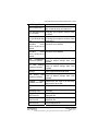
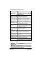
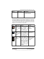
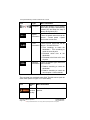
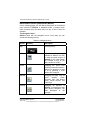
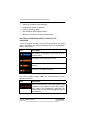
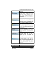
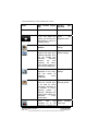
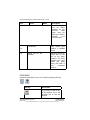
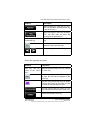
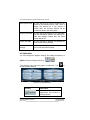
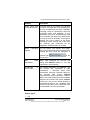
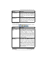
DISPLAYS AND CONTROLS
The table below describes the AV8OR displays and controls that are
displayed in Figure 1-3:
Table 1-1 Displays and Controls
FIG
NO
1
DISPLAY OR
CONTROL
Touch screen
2
POWER key
3
MENU key
4
LED charging status
indicator
Shows the status of the
charging system while the unit
is being charged.
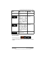
5
SD slot and SD card
The SD slot holds a SD card
which contains the aviation
and automotive navigation
software.
6
LOCK tab
The LOCK tab disables all
controls and stops the touch
screen from responding to
taps.
7
6 VDC power
connector
This connector lets the unit
receive power from an AC or
an automotive DC.
D200803000008
Rev 5 Mar 2012
DESCRIPTION
4.3 inch TFT touch screen.
The resolution is 480 x 272
pixels.
The POWER key is used to
turn the unit on and off and
also can put the unit into
Sleep mode and wake the unit
from Sleep mode.
The MENU key returns the
user to the main menu from
any program in the unit.
Getting Started
Page 1-3
© Honeywell International Inc. Do not copy without express permission of Honeywell
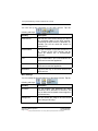
Honeywell Bendix/King AV8OR Handheld User’s Guide
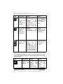
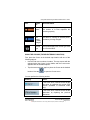
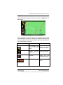
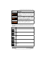
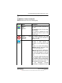
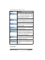
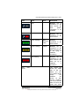
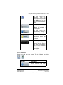
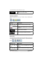
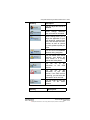
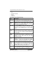
FIG
NO
8
DISPLAY OR
CONTROL
Microphone
9
USB/Serial port
10
AV-IN port
11
Headset jack
12
Volume control knob
The volume control controls
the volume of the sound
through the rear speaker or
the Headset jack if a headset
is plugged in.
13
External GPS antenna
jack
The remote GPS antenna jack
allows the user to plug in the
remote GPS antenna that is
supplied with the unit for
better satellite reception.
14
Stylus
The stylus allows the user to
precisely tap the touch screen.
Getting Started
Page 1-4
DESCRIPTION
The microphone is used for
Bluetooth connections to cell
phones.
This is used for a standard
USB connection to a PC to
download movies, pictures, Ebooks and new updates to the
navigational software. Also
used for a RS 232 connection
to external hardware with an
optional cable.
Future expansion
The headset jack accepts a
standard headphone miniature
stereo adapter so the user can
listen to music or movies from
the unit.
D200803000008
Rev 5 Mar 2012
© Honeywell International Inc. Do not copy without express permission of Honeywell
Honeywell Bendix/King AV8OR Handheld User’s Guide
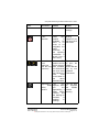
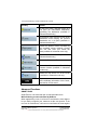
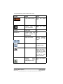
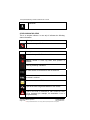
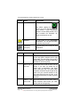
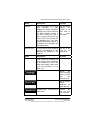
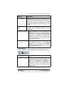
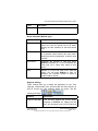
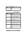
FIG
NO
15
DISPLAY OR
CONTROL
Removable battery
cover
16
Internal speaker
17
Reset button
DESCRIPTION
A replaceable battery is
included with the unit. An
optional battery with a longer
life is also available. The serial
number for the unit is located
on the case under the battery.
AV8OR has an Internal
speaker for music, movies,
routing instructions.
The reset button reboots the
AV8OR unit.
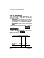
Supplied software and Equipment
The SD card on the AV8OR Handheld comes preloaded with a
navigation map for the GoFly program and the GoDrive program.
Different maps for different regions are available. Please visit the
bendixking.com/av8or website to browse the available regions,
purchase a replacement SD card for your current region or to
purchase a SD card for a different region.
For Automotive map subscriptions and software updates, visit the
naviextras.com website.
See the Subscriptions and Updates section on page 6-18 for more
information.
D200803000008
Rev 5 Mar 2012
Getting Started
Page 1-5
© Honeywell International Inc. Do not copy without express permission of Honeywell
Honeywell Bendix/King AV8OR Handheld User’s Guide
The AV8OR Handheld comes with the standard equipment that
follows:
Table 1-2 Standard Equipment
ITEM
1
PART NUMBER
066-01207-0099
2
3
005-03702-0002
005-03702-0003
4
5
6
7
8
9
10
005-03702-0004
005-03702-0005
005-03702-0007
005-03702-0009
005-03702-0010
005-03702-0012
005-03702-0013
DESCRIPTION
GPS Base Display Unit, with 800
mAh Battery and battery mounting
bracket
12-28 VDC Adaptor
120/220 VAC Adapter (with electrical
plug)
PC/USB Cable
Carrying Bag
Aviation Mount
Automotive Windshield Mount
Earphone
CD – User manual
Quick Reference Guide
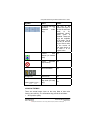
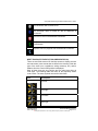
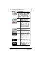
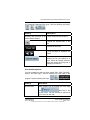
Optional Equipment
The following accessories are available for the AV8OR:
Table 1-3 Optional Equipment
ITEM
1
2
PART NUMBER
005-03702-0006
005-03702-0014
3
4
005-03702-0008
005-03702-0017
DESCRIPTION
Remote GPS Antenna
1600 mAh Battery, (with mounting
bracket)
Automotive Dashboard Mount
RS232 Cable
NOTE: The list of optional equipment may change in the future. For
the latest list of options or to order a part, please visit the
bendixking.com/av8or website.
Getting Started
Page 1-6
D200803000008
Rev 5 Mar 2012
© Honeywell International Inc. Do not copy without express permission of Honeywell
Honeywell Bendix/King AV8OR Handheld User’s Guide
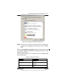
Charging the internal battery
Before using this unit for the first time or when replacing the internal
battery with a new battery, the internal battery in the AV8OR must be
charged.
Find the power connector (7) on the right side of the unit. Refer
to Figure 1-3.
Recharge the unit by either using the DC power adapter or the
120/220V AC adapter.
The LED charging indicator (4) on the unit shows a yellow light while
the unit is charging.
Figure 1-4: Charging with AV8OR turned off
When the unit is completely charged, the yellow light changes to a
green light. If the unit is turned on while charging, the charging
animation in the top right portion of the screen also displays a green
battery with full bars.
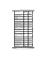
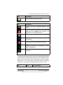
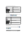
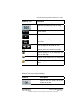
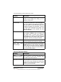
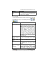
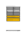
The table below shows the different charge levels.
Table 1-4: Battery Charge Level
Status
Full
Good
Medium
D200803000008
Rev 5 Mar 2012
Charge
Level
> 75%
> 50% & <
75%
> 25% & <
Number of bars on
icon
5
4
Color
Green
Green
3
Yellow
Getting Started
Page 1-7
© Honeywell International Inc. Do not copy without express permission of Honeywell
Honeywell Bendix/King AV8OR Handheld User’s Guide
Status
Charge
Level
50%
> 5% & <
25%
< 5%
Low
Critical
NOTE:
Number of bars on
icon
Color
2
Yellow
1
Red
Battery recycling is encouraged. When replacing the
battery, dispose the old battery in accordance with Local
and National Disposal Regulations.
Figure 1-5: Charge is completed
This section explains how to enter and select information with the
AV8OR.
Understanding Terms
The AV8OR unit is designed to allow quick, convenient selection of
navigation options and data entry. As you progress through this
user’s manual, you are directed to tap a specific soft key or highlight
a field on the screen. In order to highlight a field, just touch the field
on the screen.
Touch or Tap: Use your finger or the AV8OR stylus to touch the
screen on the soft key and remove it quickly
Double tap: Use your finger or the stylus to touch the screen twice
on a field. The double tap is used to open a menu selection box.
Getting Started
Page 1-8
D200803000008
Rev 5 Mar 2012
© Honeywell International Inc. Do not copy without express permission of Honeywell
Honeywell Bendix/King AV8OR Handheld User’s Guide
Pan: Touch the screen and move your finger or stylus across the
screen while continuing to touch the screen. This allows you to scroll
the map and change settings.
Highlight: Touch on the screen to select the desired individual
fields. Moving the highlight to a desired location allows the user to
make a selection, begin data entry, or scroll through a list.
Field: The location on a page where data or an option can be
entered and shown.
Scroll Bar: When viewing a list of items that is too long to show on
the screen, a scroll bar appears along the right side of the list. To
scroll through a list, hold your finger or stylus on the scroll bar and
move your finger or stylus up or down and the list of items will move
up or down too.
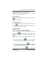
Turning AV8OR on/off
The first time your new AV8OR is turned on, the GPS receiver must
collect satellite data and establish its present location. Before you
turn on the unit, make sure that it has a clear and unobstructed view
of the sky to receive satellite signals.
1. Ensure that the “Lock” switch is unlocked.
2. Hold the Power Key down until the blue screen shows.
Figure 1-6: AV8OR Power Up
3. To turn off the AV8OR, press and hold the Power Key until
POWER OFF screen shows.
D200803000008
Rev 5 Mar 2012
Getting Started
Page 1-9
© Honeywell International Inc. Do not copy without express permission of Honeywell
Honeywell Bendix/King AV8OR Handheld User’s Guide
Figure 1-7: AV8OR Power off
AV8OR SLEEP MODE
AV8OR can be put into sleep mode as shown in the figure below.
AV8OR, while in sleep mode, continues to run in a low power mode.
Figure 1-8: AV8OR Sleep Mode
TURN SLEEP MODE ON AND OFF
1. To put the unit in Sleep mode, press and quickly release the
Power soft Key until Sleeping shows on the screen for a moment,
then the screen goes blank.
2. To wake up the unit, press and quickly release the Power soft
Key.
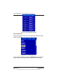
Main Menu
After the logo startup page shows, the MAIN MENU is displayed.
Getting Started
Page 1-10
D200803000008
Rev 5 Mar 2012
© Honeywell International Inc. Do not copy without express permission of Honeywell
Honeywell Bendix/King AV8OR Handheld User’s Guide
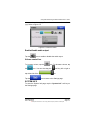
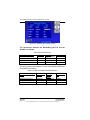
Figure 1-9: Main Menu
Getting satellite signals
When the AV8OR is turned on, it automatically begins to search for
satellite signals. This process can take a few minutes. Be sure the
device has a clear and unobstructed view of the sky.
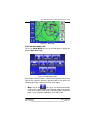
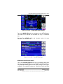
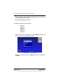
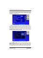
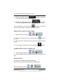
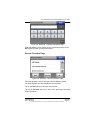
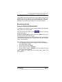
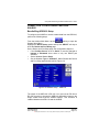
VIEW GPS STATUS FROM SETTINGS
You can monitor GPS status by tapping the Settings soft key on the
Main Menu page (refer to Figure 1-9, and tapping on the GPS
Status soft key (refer to Figure 1-10).
Figure 1-10: Settings Page
The GPS Status page provides a visual reference of satellite
acquisition, receiver status, current position and a reset mechanism.
D200803000008
Rev 5 Mar 2012
Getting Started
Page 1-11
© Honeywell International Inc. Do not copy without express permission of Honeywell
Honeywell Bendix/King AV8OR Handheld User’s Guide
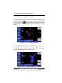
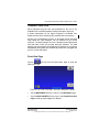
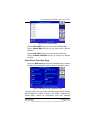
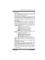
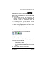
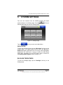
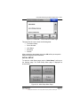
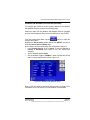
GPS Signal Strength
The GPS Signal Strength page is the default page for GPS Status.
As the receiver locks onto satellites, a bar appears for each satellite.
The bar shows the signal strength for each satellite. The bar
changes color from grey to blue when the satellite is locked.
Figure 1-11: GPS Signal Strength Page – Locked and Unlocked
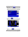
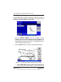
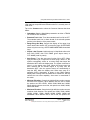
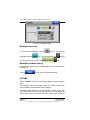
Current Position
Tapping this soft key displays the longitude, latitude, altitude (ALT)
and UTC time information for the current position when the device
has acquired a GPS satellite lock.
Figure 1-12: GPS Information of Current position
Getting Started
Page 1-12
D200803000008
Rev 5 Mar 2012
© Honeywell International Inc. Do not copy without express permission of Honeywell
Honeywell Bendix/King AV8OR Handheld User’s Guide
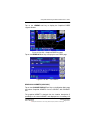
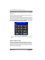
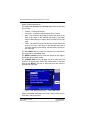
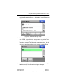
GPS Data Flow
Tapping this soft key shows the GPS national marine electronics
association (NMEA) data in real-time.
Figure 1-13: GPS Data flow
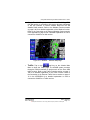
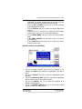
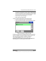
Satellite Acquisition Reset
Tapping this soft key causes the GPS engine to reset. If the unit has
difficulty acquiring satellites, tapping the GPS reset soft key will clear
the GPS engine memory.
Figure 1-14: GPS Reset
Tap the
soft key to return to the Settings page.
D200803000008
Rev 5 Mar 2012
Getting Started
Page 1-13
© Honeywell International Inc. Do not copy without express permission of Honeywell
Honeywell Bendix/King AV8OR Handheld User’s Guide
This Page
Intentionally Left Blank
Getting Started
Page 1-14
D200803000008
Rev 5 Mar 2012
© Honeywell International Inc. Do not copy without express permission of Honeywell
Honeywell Bendix/King AV8OR Handheld User’s Guide
2.
AVIATION MODE OPERATION
NOTE: Chapter 2 documents the 02/05 version of the Go Fly
program. The version number is shown at the bottom left
corner of the Initial Title Page (Figure 2-1) upon startup. If
using
an
earlier
version,
go
to
you
are
bendixking.com/av8or for instructions on how to update
your AV8OR to the latest version.
BASIC OPERATION
This section introduces how to start the aviation mode navigation,
and what the status of the program is during the initialization
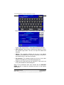
process.
Aviation Mode
On the Main Menu page, tap the
Aviation mode navigation program.
icon to start the
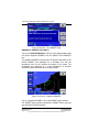
PROGRAM STARTUP
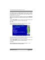
While the Aviation mode is starting, a startup title page is displayed,
as shown in the figure below.
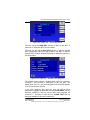
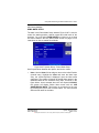
Figure 2-1: Initial Title Page
A self-test status window is displayed under the title box. The selftest checks to make sure the internal navigation, cartography and
terrain databases are correct. While the self-test is checking these
databases, the window header SELF TEST IN PROGRESS is
displayed in yellow.
D200803000008
Rev 5 Mar 2012
Basic Operation
Page 2-1
© Honeywell International Inc. Do not copy without express permission of Honeywell
Honeywell Bendix/King AV8OR Handheld User’s Guide
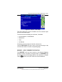
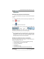
A green check mark is placed to the right of each test item as it is
checked.
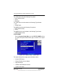
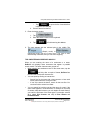
If the initial self-test fails, the unit is unable to continue operating
safely. A red
is displayed in place of the check mark and the first
soft key changes to HELP, as shown in the figure below.
Figure 2-2: Self Test Failed
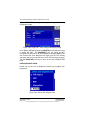
When the HELP soft key is tapped, a caution message is displayed
as shown in the figure below.
Figure 2-3: Self Test Failed Caution
The unit should be turned off and then turned back on. If
AV8OR still fails the self-test, please contact customer support.
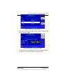
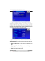
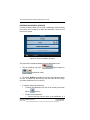
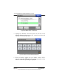
If the self-test finishes successfully, the self-test window header
changes to SELF TEST COMPLETED in green, as shown in the
figure below.
Basic Operation
Page 2-2
D200803000008
Rev 5 Mar 2012
© Honeywell International Inc. Do not copy without express permission of Honeywell
Honeywell Bendix/King AV8OR Handheld User’s Guide
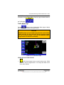
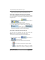
Figure 2-4: SELF TEST COMPLETED Page
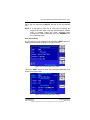
The SELF TEST COMPLETED page shows for 2 seconds then the
final title page is displayed as shown in the figure below.
Figure 2-5: Final Title Page
The final title page shows the subscription expiration dates of the
present database, installed charts and the data providers in a
scrollable window (if needed). Use the AV8OR as an aid to
situational awareness only when the database is current.
The software level is shown on the bottom left side of the screen
(current software level is 02/05).
For additional information on the present software and database
versions, please go to the System Setup page and tap on the Status
Page soft key to bring up the System Status Menu. Highlight the
Software and Database Versions and tap the Select soft key to
show the present software and database versions.
D200803000008
Rev 5 Mar 2012
Basic Operation
Page 2-3
© Honeywell International Inc. Do not copy without express permission of Honeywell
Honeywell Bendix/King AV8OR Handheld User’s Guide
The user can browse the Bendix/King web page at
bendixking.com/av8or to see if a newer version of the software or
database is available.
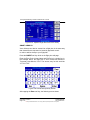
If the OK soft key is pushed to acknowledge the Jeppesen database,
the Aviation Map page is displayed, as shown in Figure 2-7: Map
Page.
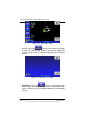
Figure 2-7If the DEMO MODE soft key is tapped, then AV8OR will
enter a simulation mode.
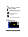
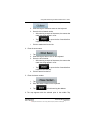
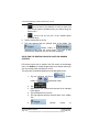
DEMO MODE
Demo Mode lets the user become familiar with handling the AV8OR
system on the ground by running in a simulation mode. When the
AV8OR is in Demo Mode, it performs the same as when it is
receiving valid sensor signals to use the various functions. Demo
Mode can only be activated on the final title page during startup, as
shown in
Figure 2-5. After tapping the DEMO MODE soft key, the simulator
shows a caution page which must be acknowledged before
continuing, as shown in the figure below.
Figure 2-6: Demo Mode
Tap the OK soft key to acknowledge the caution and then the Map
page is displayed.
Basic Operation
Page 2-4
D200803000008
Rev 5 Mar 2012
© Honeywell International Inc. Do not copy without express permission of Honeywell
Honeywell Bendix/King AV8OR Handheld User’s Guide
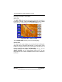
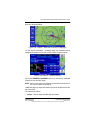
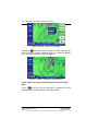
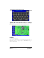
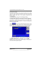
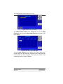
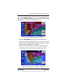
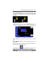
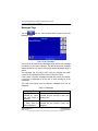
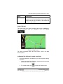
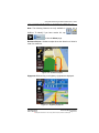
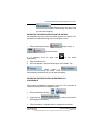
Figure 2-7: Map Page
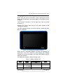
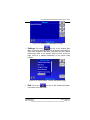
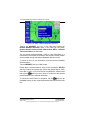
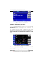
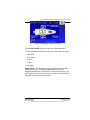
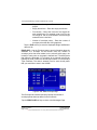
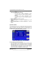
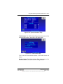
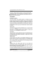
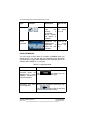
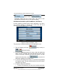
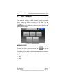
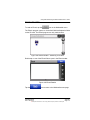
AVIATION MAIN MENU PAGE
Tap on the MAIN MENU soft key on the Map page to display the
Aviation Main Menu Page.
Figure 2-8: Main Menu Page
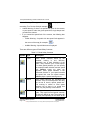
An example of each function in Aviation Mode appears below. Each
function has a specific use and is discussed later in this guide. The
following figures are each of the function’s first pages.
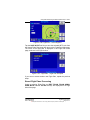
•
Map: Tap on the
soft key on the Aviation Main Menu
to return to the Moving Map page. The Map mode is the primary
mode of the system. Refer to the VFR Moving Map Function on
page 2-10 for a detailed explanation of the MAP mode.
D200803000008
Rev 5 Mar 2012
Basic Operation
Page 2-5
© Honeywell International Inc. Do not copy without express permission of Honeywell
Honeywell Bendix/King AV8OR Handheld User’s Guide
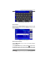
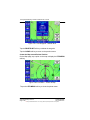
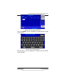
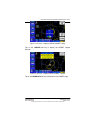
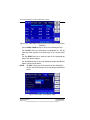
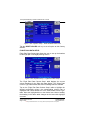
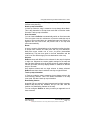
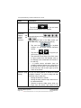
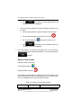
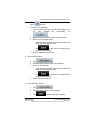
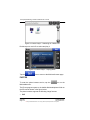
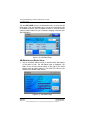
•
Flight Plans: Tap on the
soft key on the Aviation
Main Menu to show the Flight Plan Index page. The Flight Plan
Index page allows user Waypoints (WPT) and flight plans be
edited and/or created. Refer to the Flight Plan Function section
on page 2-62 for a detailed explanation of the use of flight plans.
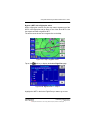
Figure 2-9: Flight Plan – Flight Plan Index Page
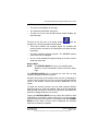
•
Panel: Tap on the
soft key on the Aviation Main Menu
to show the Panel page. Refer to the PANEL FUNCTION section
on page 2-128 for a detailed explanation of the Panel Page.
Figure 2-10: Panel Page
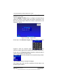
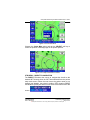
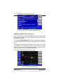
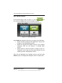
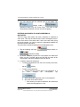
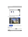
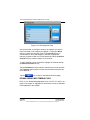
•
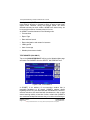
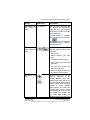
Weather: Tap on the
soft key on the Aviation Main
Menu to show the Weather page (if weather is enabled in Device
Basic Operation
Page 2-6
D200803000008
Rev 5 Mar 2012
© Honeywell International Inc. Do not copy without express permission of Honeywell
Honeywell Bendix/King AV8OR Handheld User’s Guide
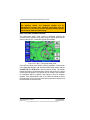
Setup). The AV8OR system connects with a Bendix/King KDR610 XM receiver or a WxWorx XM receiver through a Bluetooth
or RS 232 interface to receive weather data from the XM
Satellite Radio network. Refer to the Weather Function section
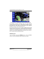
on page 2-86 for a detailed explanation of the Weather function.
Refer to the Connection to An External Weather Source section
in the Appendix on page 6-9 for a detailed explanation on how to
connect the AV8OR to an XM receiver.
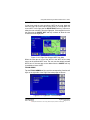
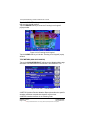
Figure 2-11: Weather – Weather Map Page
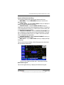
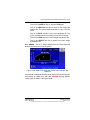
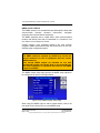
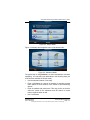
•
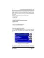
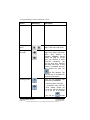
Traffic: Tap on the
soft key on the Aviation Main
Menu to show the Traffic page. The AV8OR system connects
through a RS-232 interface to devices such as the Zaon XRX
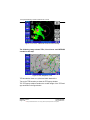
traffic receiver. Refer to the Traffic Function section on page 2120 for a detailed explanation of the Traffic function. Refer to
the Connection to An External Traffic Source section on page 616 in the APPENDIX for a detailed explanation on how to
connect the AV8OR to a Traffic receiver.
D200803000008
Rev 5 Mar 2012
Basic Operation
Page 2-7
© Honeywell International Inc. Do not copy without express permission of Honeywell
Honeywell Bendix/King AV8OR Handheld User’s Guide
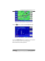
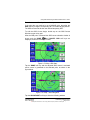
Figure 2-12: Traffic Main Page
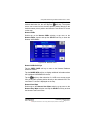
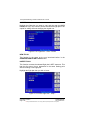
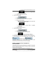
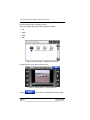
• Taxiway: Tap on the
soft key on the Aviation Main Menu
to show the Taxiway page. Refer to the Taxiways FUNCTION
section on page 2-125 for a detailed explanation of the Taxiway
function
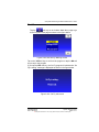
Figure 2-13: Taxiways – Info Page
soft key on the Aviation Main
• Auxiliary: Tap on the
Menu to show the Messages page. Refer to the Messages Page
section on page 2-130 for a detailed explanation of the Message
function.
Basic Operation
Page 2-8
D200803000008
Rev 5 Mar 2012
© Honeywell International Inc. Do not copy without express permission of Honeywell
Honeywell Bendix/King AV8OR Handheld User’s Guide
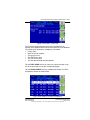
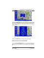
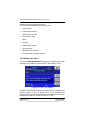
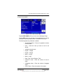
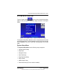
Figure 2-14: Messages – Messages Info Page
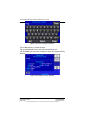
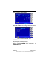
•
Settings: Tap on the
soft key on the Aviation Main
Menu to show the Settings page. Use the System Setup Menu to
setup map, navigation, data fields, flight plan and other display
preferences. Refer to the System Setup Function section on
page 2-145 for a detailed explanation of the system setup
function.
Figure 2-15: System Setup – System Setup Menu page
•
Exit: Tap on the
soft key on the Aviation Main Menu
to exit back to the Main Menu.
D200803000008
Rev 5 Mar 2012
Basic Operation
Page 2-9
© Honeywell International Inc. Do not copy without express permission of Honeywell
Honeywell Bendix/King AV8OR Handheld User’s Guide
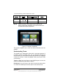
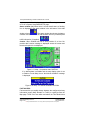
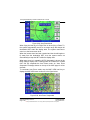
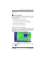
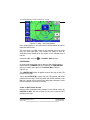
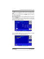
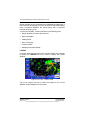
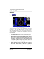
VFR MOVING MAP FUNCTION
The AV8OR features a real-time moving map that can do much more
than just plot your course. The core capability of AV8OR MAP mode
function is its intuitive mapping and navigation function, which is
capable of displaying highly detailed, vectored (point and line) maps.
This detailed vector data includes road over flown data, street
address data, airspace boundaries, airports, Navigational Aid
(NAVAID)s, lakes, rivers, coastlines, cities, highways and terrain
elevation data used to help situational awareness.
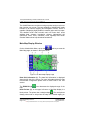
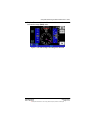
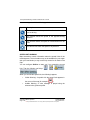
Main Map Display Window
On the Aviation Main Menu, tap on the
Main Map page, as shown in the figure below.
soft key to enter the
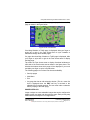
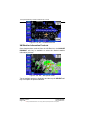
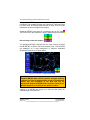
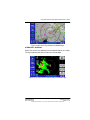
Figure 2-16: Main Map Display Page
Data field information (1): The data field information is displayed
along the left side of the screen. For more information about the data
field window configuration please refer to Data Fields in the next
section.
The ZOOM IN (2)
icon decreases the displayed range of the
map.
North Pointer (3): In the upper left corner of the Map display is a
North pointer. The pointer has a triangle shape
. The north pointer
always points north to help orient the map view. Double tapping on
VFR Moving Map Function
Page 2-10
D200803000008
Rev 5 Mar 2012
© Honeywell International Inc. Do not copy without express permission of Honeywell
Honeywell Bendix/King AV8OR Handheld User’s Guide
the north pointer toggles the map orientation between North Up and
the Track Up mode.
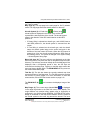
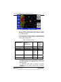
Map Page (4): The map page is the main page for Go Fly aviation
mode. The map page shows the aircraft position on the map.
Aircraft Symbol (5): A Fixed wing
or Rotary wing
aircraft symbol is displayed in the center of the screen that
represents the actual position of the aircraft. The aircraft symbol
points in the direction of the GPS track based on a valid GPS
position fix.
• If Rotary Wing is selected as aircraft type, and AV8OR loses a
valid GPS position fix, the aircraft symbol is removed from the
screen.
• If Fixed Wing is selected as the aircraft type, and the aircraft
stops, the aircraft symbol stays on the screen and point in the
direction of the last known GPS track. When the GPS speed is
greater than 3 kts, the aircraft symbol follows the GPS track as
the heading source. The symbol is changed in the System Setup
– General System Setup page.
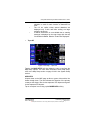
Menu Soft keys (6): The menu soft keys are displayed on the right
side of the screen. They allow the user to navigate through the menu
directory. The soft keys are shown initially when the Map page is first
displayed. After a configurable period of time, the soft keys are
removed from the Map page. Tapping on the Map page causes the
menu soft keys to display again. The MAIN MENU soft key returns to
the Aviation Main Menu page.
Title Bar (7): The title bar shows the currently selected map view
across the bottom of the Map page. The Title Bar area also provides
fast access to primary pages. For more information on how fast
access works, refer to the Fast Access section on page 2-12.
The ZOOM OUT (8)
map.
icon increases the displayed range of the
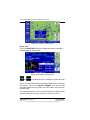
Map Range (9): The current range (labeled RNG
) is displayed
in the range tag window in the lower left corner of the display. The
range distance unit (nautical miles, statute miles or kilometers) is
configured in the System Setup-GENERAL SYSTEM SETUP page.
Range is measured on the map as the distance from the center of
the aircraft symbol to the outer ring around the aircraft. The inner
D200803000008
Rev 5 Mar 2012
VFR Moving Map Function
Page 2-11
© Honeywell International Inc. Do not copy without express permission of Honeywell
Honeywell Bendix/King AV8OR Handheld User’s Guide
ring is at one-half the displayed range value. These rings are turned
on or off in System Setup-MAP SETUP page.
Status window (10): When there is a new aircraft status, a flashing
icon is displayed in the status window in the left bottom of the data
window column
. The status window also shows the battery
condition and the status of the XM weather receiver (if installed) and
traffic information (if installed) .
.
Caution: When AV8OR has lost its GPS position fix, a blue “No
position data” caution message is displayed across the screen and
the aircraft symbol is not displayed.
Figure 2-17: Map – No position data CAUTION
If no altitude data is available and the map display option is set
to Relative Terrain Map, then a “No Altitude Available” message
is displayed.
Figure 2-18: Map – No Altitude Available CAUTION
FAST ACCESS
Fast access lets you rapidly change between the configured primary
information pages (Map, Weather or Traffic) or rapidly access the
Map page. There is an area within and above the Title Window that
VFR Moving Map Function
Page 2-12
D200803000008
Rev 5 Mar 2012
© Honeywell International Inc. Do not copy without express permission of Honeywell
Honeywell Bendix/King AV8OR Handheld User’s Guide
you can use to change to a different page or jump back to the Map
page as shown in the figure below.
Figure 2-19: Fast Access
If the Map, Weather or Traffic page, is displayed, slide your finger or
stylus left or right in the Fast Access area to cycle forwards or
backwards through the available pages.
If a page other than Map, Weather or Traffic page is displayed, slide
your finger or stylus left or right in the Fast Access area to display
the Map page.
Tap within the Fast Access area to display directional windows on
each side of the Fast Access area as shown in the figure above. The
directional windows show which page will be displayed if you touch
and slide your finger or stylus in that direction.
The following pages do not have Fast Access availability.
• Start Up pages
• Main Menu
• Exit
• Any page that has an edit selection window. (This is a menu list
that is displayed when the EDIT soft key is touched or the
editable field is double touched. The user must make a selection
before jumping to the MAP page)
IMAGE OVERLAYS
Image overlays are user selectable images that can be configured to
display on the map page and other primary maps. Each primary map
allows different overlays to be configured for it.
D200803000008
Rev 5 Mar 2012
VFR Moving Map Function
Page 2-13
© Honeywell International Inc. Do not copy without express permission of Honeywell
Honeywell Bendix/King AV8OR Handheld User’s Guide
The following table lists the image overlays that can be displayed on
the primary maps:
• Flight Plan: When there is an active flight plan, the legs and
turning points of the flight plan are shown (Including Direct-To).
• Traffic: When a traffic device has a connection with AV8OR and
has been enabled, traffic icons are displayed on the map page, if
available.
• Flight Log Trail: Flight log points are plotted when the flight log
overlay has been enabled for the current map scale.
The following overlays require a current XM weather subscription
and a connection to a XM weather receiver to be displayed.
• Metar: If a meteorological aviation report (METAR) is available,
the METAR icon shows on the map.
• TFR: If a TFR is available, a yellow and black dashed TFR
boundary is displayed on the page.
• Lightning: If lightning strike data is available, lightning strike
icons are displayed on the page.
• Precip Type: If precipitation type data is available, the precip
type icon is displayed on the page.
• Nexrad Coverage: If Nexrad coverage is available, it is displayed
on the page.
• Cloud Top: If cloud top data is available, it is displayed on the
page.
• Storm Cell: If storm cell data is available, it is displayed on the
page.
The table below show which overlays are available for each primary
map: An “X” in the column indicates that the overlay is available for
the primary page at the top of the column
Table 2-1: Image Overlays on Primary Maps
Flight
Topo
On Map
Topo
Off Map
Nexrad
Map
X
X
X
VFR Moving Map Function
Page 2-14
Metar,
Pirep,
Winds
Aloft
Maps
X
Airmet
Sigmet
Maps
X
D200803000008
Rev 5 Mar 2012
© Honeywell International Inc. Do not copy without express permission of Honeywell
Honeywell Bendix/King AV8OR Handheld User’s Guide
Plan
Traffic
Flight
Log Trail
Metar
TFR
Lightning
Precip
Type
Nexrad
Cloud
Top
Storm
Cell
Topo
On Map
Topo
Off Map
Nexrad
Map
Metar,
Pirep,
Winds
Aloft
Maps
Airmet
Sigmet
Maps
X
X
X
X
X
X
X
X
X
X
X
X
X
X
X
X
X
X
X
X
X
X
X
Overlays are configured in the Map Setup section. The Topo On
Map Overlay page is shown in the figure below.
Figure 2-20:Topo On Map - Overlay Setup
Refer to the Map Setup section on page 2-148 for more information
on how to configure the image overlays.
D200803000008
Rev 5 Mar 2012
VFR Moving Map Function
Page 2-15
© Honeywell International Inc. Do not copy without express permission of Honeywell
Honeywell Bendix/King AV8OR Handheld User’s Guide
CAUTION
The lightning strikes and displayed weather are for
informational purposes only. Weather information from the
XM receiver is not real time and the displayed weather images
should not be used for tactical flying.
MAP PAGE POINTER/NON-POINTER:
The Non-pointer MAP mode screen is displayed showing the
aircraft’s current position on the map using the aircraft symbol in the
center of the screen, if valid GPS signals are available.
Figure 2-21: Map – Non-pointer Map mode
If the soft keys have been hidden, touching anywhere on the screen
in the Main Map Window, will activate a black arrow pointer and the
CLEAR PTR and PTR MENU soft keys will be shown. The pointer
follows the finger or stylus around the screen until the finger or stylus
is lifted from the screen. The pointer can be moved in any direction
to interrogate WPTs or specific map features, such as: airports,
airspace, user defined WPTs and so on. While the pointer is active
the map stops moving to permit easier pointer access to objects, and
the aircraft moves over the map.
VFR Moving Map Function
Page 2-16
D200803000008
Rev 5 Mar 2012
© Honeywell International Inc. Do not copy without express permission of Honeywell
Honeywell Bendix/King AV8OR Handheld User’s Guide
Figure 2-22: Map – Pointer Map mode
In Pointer Map mode, the pointer tag window displays the pointer
position in the currently selected coordinate system. Below the
pointer tag window, the title window component displays the bearing
and distance of the pointer relative to the aircraft’s position.
Figure 2-23: Map – Pointer Tag Window / Title Window
The pointer is removed from the screen after 30 seconds of no
further input (touching and dragging of the pointer).
Auto-Hide Soft keys: When the map mode is displayed without
touching any control, the on-screen soft key labels are removed from
the screen after a period of time that is configurable, as shown
in Figure 2-24. The default time is 30 seconds.
Figure 2-24: Map – Without soft keys
D200803000008
Rev 5 Mar 2012
VFR Moving Map Function
Page 2-17
© Honeywell International Inc. Do not copy without express permission of Honeywell
Honeywell Bendix/King AV8OR Handheld User’s Guide
For configuration of the Auto-Hide Soft keys, please refer to
the General System Setup section on page 2-146 in the System
Setup section.
The labels are redisplayed when the user touches the screen. This
feature maximizes the visible area for mapping. This feature can be
disabled by setting the Auto-Hide Keys on the Map Mode Page to
OFF in the General System Setup page (Refer to the General
System Setup section on page 2-146).
DATA FIELDS
Up to four data windows can show at a time on the left side of the
map page. Up to 9 data windows can be configured for display. The
five data windows that do not show on the page are displayed by
dragging the data windows up or down to show the data fields that
are off screen.
Data fields are selected in the System Setup Menu, Refer to
the Data Field Setup section on page 2-156.
The Data Fields that follow can be selected for display on the map
page.
Altitude Data Field
The Altitude data field displays the highest priority
enabled GPS altitude source.
Bearing Data Field
The Bearing data field displays the bearing of the
current destination WPT for the aircraft position in degrees relative to
magnetic north.
Course Deviation Indicator (CDI) Data Field
The Course Deviation Indicator data field displays the
perpendicular distance from the aircraft position to the desired track.
The triangle in the center displays whether the aircraft is going TO or
FROM the destination WPT. If the triangle points upwards, the
aircraft is going TO the destination. If the triangle points downwards,
the aircraft is going FROM the destination.
The table below displays the full scale limits for the CDI.
VFR Moving Map Function
Page 2-18
D200803000008
Rev 5 Mar 2012
© Honeywell International Inc. Do not copy without express permission of Honeywell
Honeywell Bendix/King AV8OR Handheld User’s Guide
Table 2-2 Course Deviation Limits
Units
Nautical miles
Statute miles
Kilometers
Available CDI limits
0.3 nm, 1.0 nm and 5.0 nm
0.4 sm, 1.0 sm and 5.0 sm
0.6 km, 2.0 km and 10.0 km
Departure Time Data Field
The departure time data field displays the departure
time when the ground speed of the aircraft is 20 knots or higher. The
time is displayed in HH:MM format. The time is dashed if there is no
departure time available.
Destination Waypoint Ident Data Field
The DEST WPT data field displays the ident of the final
destination waypoint.
If the waypoint ident is unavailable then dashes are displayed.
When a waypoint identifier is displayed in the data field, the waypoint ident
data window is an “active” data window. Double tap” on the data window to
go to the waypoint information page.
The waypoint ident is truncated to fit into the size of the data
window.
Distance to Waypoint Data Field
The distance to waypoint data field displays the
distance from the aircraft to the destination waypoint. The distance is
displayed in the currently selected units for distance.
Desired Track Data Field
The desired track data field displays the magnetic angle
from the start waypoint to the destination waypoint as an integer
value
En-Route Safe Altitude Data Field
The en-route safe altitude data field displays the highest
“minimum off-route altitude” along the track line between the start
D200803000008
Rev 5 Mar 2012
VFR Moving Map Function
Page 2-19
© Honeywell International Inc. Do not copy without express permission of Honeywell
Honeywell Bendix/King AV8OR Handheld User’s Guide
and destination waypoints. The ESA is displayed in the currently
selected altitude units.
Estimated Time of Arrival for Next Leg Data Field
The ETA LEG data field displays the calculated arrival
time calculated as the distance to the next waypoint, divided by the
ground speed, plus the current time.
Estimated Time of Arrival Data Field
The estimated time of arrival data field displays the
calculated arrival time calculated as the distance to the destination
waypoint, divided by the ground speed, plus the current time.
Estimated Time En-Route for next Leg Data Field
The ETE LEG data field displays the calculated time en
route as the distance to the next waypoint, divided by the ground
speed. If the ETE is greater than 10 minutes then the format is
HH:MM. If HH is less than 10 then no leading zeroes are displayed.
Otherwise the format is MM:SS, with leading zeroes displayed. If the
ETE is invalid or greater than 24 hours then “--:--“ is displayed.
Estimated Time En-Route Data Field
The estimated time en-route data field displays the
calculated time en route as the distance to the destination waypoint,
divided by the ground speed. If the ETE is greater than 10 minutes
then the format is HH:MM. If HH is less than 10 then no leading
zeroes are displayed. Otherwise the format is MM:SS, with leading
zeroes displayed. If the ETE is invalid or greater than 24 hours then
“--:--“ is displayed.
Examples are shown in the following table:
Table 2-3 Calculated Time En Route
1hr 55 min
1min:55 sec
24 min :
35 sec
VFR Moving Map Function
Page 2-20
1
01
:
:
00
:
55
55
24
35
D200803000008
Rev 5 Mar 2012
© Honeywell International Inc. Do not copy without express permission of Honeywell
Honeywell Bendix/King AV8OR Handheld User’s Guide
Flight Time Data Field
The flight time data field displays the current flight
duration in HH:MM format. The flight timer displays the current time
in flight or, if the flight has ended, the duration of the flight just
ended. The flight timer begins counting when the ground speed
exceeds 20 knots. The flight timer continues until the unit shuts
down, or until the ground speed has been below 3 knots for 5
minutes. If the ground speed exceeds 20 knots after the flight time
had previously stopped then the flight time continues from the
previous flight time.
Groundspeed Data Field
The ground speed data field displays the current aircraft
ground speed in the configured units.
Minimum Safe Altitude Data Field
The minimum safe altitude data field displays the
minimum off-route altitude (from the Jeppesen MORA database.) at
the current aircraft position.
The MSA value is displayed in the currently selected units for
altitude.
If the position is invalid then the MSA value is displayed as dashes.
Near Position Data Field
The near position data field displays the current aircraft
position relative to a near-by database feature that is determined by
the user configuration.
If the displayed distance to the nearest selected database feature is
less than 0.1, in the currently selected distance units, then the
position is described as ‘AT’ the database feature.
If the distance is 0.1 or more then the compass bearing from the
database feature is also displayed.
D200803000008
Rev 5 Mar 2012
VFR Moving Map Function
Page 2-21
© Honeywell International Inc. Do not copy without express permission of Honeywell
Honeywell Bendix/King AV8OR Handheld User’s Guide
The bearing is one of sixteen compass bearings (e.g. ENE, NE, and
SSW).
The icon, used to display the database item on the map, is displayed
immediately below the ident.
The ident is displayed to the maximum width displayable in the
selected data window size.
Present Position Data Field
The present position data field displays the coordinates
of the aircraft position in the currently selected coordinate system.
If the present position is unknown then dashes are displayed.
Stop Watch Data Field
The Stop Watch data field displays the current value of
the Stop Watch in MM:SS format.
The time counts up from 00:00 when enabled (started) and the text
color changes to yellow.
The time stops counting when disabled and the text color changes to
white.
The time is displayed as --:-- in white text when the window is first
displayed.
The largest value that can show is 99:59 at which time it rolls over to
00:00.
Double tap on the STP WTCH data field to start, stop or clear the
timer.
Time Data Field
The time data field displays the current system time in
the selected time zone.
The selected time zone abbreviation is displayed in the data window
title, after the word TIME.
If the time is unavailable then dashes are displayed.
The table below lists the time zones that are selectable:
VFR Moving Map Function
Page 2-22
D200803000008
Rev 5 Mar 2012
© Honeywell International Inc. Do not copy without express permission of Honeywell
Honeywell Bendix/King AV8OR Handheld User’s Guide
Table 2-4 Time Zones
Time Zone
Abbreviation
LCL
UTC
GST
GDT
ATS
ATD
EST
EDT
CST
CDT
MST
MDT
PST
PDT
AKS
AKD
HAS
HAD
SST
SDT
Description
Local
time
–
user
configurable offset from
UTC
Universal time
Greenland Standard Time
Greenland Daylight Saving
Time
Atlantic Standard Time
Atlantic Daylight Saving
Time
Eastern Standard Time
Eastern Daylight Saving
Time
Central Standard Time
Central Daylight Saving
Time
Mountain Standard Time
Mountain Daylight Saving
Time
Pacific Standard Time
Pacific Daylight Saving
Time
Alaska Standard Time
Alaska Daylight Saving
Time
Hawaii Standard Time
Hawaii Daylight Saving
Time
Samoa Standard Time
Samoa Daylight Saving
Time -
Offset
from UTC
User
defined
0:00
-3:00
-2:00
-4:00
-3:00
-5:00
-4:00
-6:00
-5:00
-7:00
-6:00
-8:00
-7:00
-9:00
-8:00
-10:00
-9:00
-11:00
-10:00
Track Angle Error Data Field
The track angle error data field displays the difference
between the desired track and the current aircraft track over ground
in integer degrees. An arrow indicates the direction to steer to
reduce the track angle error.
D200803000008
Rev 5 Mar 2012
VFR Moving Map Function
Page 2-23
© Honeywell International Inc. Do not copy without express permission of Honeywell
Honeywell Bendix/King AV8OR Handheld User’s Guide
Track Angle Data Field
The track angle data field displays the track angle of
the aircraft over the ground in integer degrees relative to magnetic
north.
Mini Traffic-Targets Data Window
The mini traffic-targets data field displays a reduced
representation of the main traffic display within a double height data
field. All of the traffic targets are displayed relative to the nose of the
aircraft. The traffic-targets only show when the Map page is in
“Track Up” mode. This prevents confusion between the main Map
page display and the mini traffic display.
The mini traffic-targets data window displays targets out to 6 nm (7
sm or 10 km).
If the main image display is set to North-Up, the message “NOT
SHOWN IN NORTH UP” is displayed within the data window.
If the currently configured traffic unit has failed the message “FAIL” is
displayed in yellow text in the center of the mini traffic-targets data
window.
If the traffic unit has been removed from the system the message
“NOT INSTALLED” is displayed in white text in the center of the mini
traffic-targets data window and no traffic-targets are displayed.
Track To Steer Data Field
The track to steer data field displays the calculated
optimum track over ground angle to be flown to achieve the desired
track to the destination waypoint as an integer value relative to
magnetic north.
Wind Vector Data Field
The wind vector data field displays the wind speed and
direction the wind is from in the presently selected speed units.
VFR Moving Map Function
Page 2-24
D200803000008
Rev 5 Mar 2012
© Honeywell International Inc. Do not copy without express permission of Honeywell
Honeywell Bendix/King AV8OR Handheld User’s Guide
The arrow represents the direction of the wind relative to true north
(direction the window is from. (As the aircraft direction changes, the
wind direction arrow follows the direction of the aircraft)
If there is a valid Track then the wind direction is be displayed as
Magnetic North otherwise displayed as True North.
If no valid wind vector data is available then “NOT AVAILABLE” is
displayed in the wind vector window.
Waypoint Ident Data Field
The waypoint ident data field displays the ident of the
current destination waypoint.
If the waypoint ident is unavailable then dashes are displayed.
When a waypoint identifier is displayed in the data field, the waypoint
ident data window is an “active” data field. Tap the waypoint ident
data field twice to display the MORE INFO window for this waypoint.
The waypoint ident is truncated to fit into the size of the data window.
Cross Track Error Data Field
The cross track error data field displays the magnitude
of, and direction to steer, to reduce the perpendicular distance
between the aircraft position and the desired track. An arrow is
displayed to the right of the cross track error value indicating the
direction to steer to reduce the cross track error.
VFR Moving Map Operation
MAP ZOOMING
ZOOM IN or ZOOM OUT changes the current map range to the next
value. Holding either soft key smoothly increments or decrements
(changes the range by 10 percent) through the ranges permitting the
user to stop at almost any range value desired. Pushing the opposite
ZOOM soft key steps the range in the opposite direction. The map
range value will be displayed on the RNG label.
The ZOOM IN and ZOOM OUT soft keys disappear when the
maximum or minimum limit is reached.
When the pilot operates the unit outside of the data base region
contained on the SD card and zooms into a range that requires the
high resolution terrain data, the pilot will see a purple background
screen color and a message stating “Outside Database Region”.
D200803000008
Rev 5 Mar 2012
VFR Moving Map Function
Page 2-25
© Honeywell International Inc. Do not copy without express permission of Honeywell
Honeywell Bendix/King AV8OR Handheld User’s Guide
This warning and alert is issued at all zoom levels where the high
resolution terrain data is not available.
MAP VIEW
The MAP VIEW soft key allows the user to select the information to
be shown on the map. Tapping the MAP VIEW soft key on the MAIN
MAP DISPLAY window brings up the CHANGE VIEW soft key.
Figure 2-25: Map – Map View Setup
Tap the SAVE & EXIT soft key to return to the Map page.
Smart Profile
The Smart Profile mode displays the vertical profile of the flight path
along the route of flight above the title bar. A cross section of the
terrain for the flight is shown on the vertical profile. A dashed line is
shown to represent the altitude of the flight path.
If Smart Profile is OFF, tapping the MAP VIEW soft key ,then the
SMART PROFILE soft key toggles Smart Profile to ON. The map
image shrinks 25% to show the SMART PROFILE on the bottom on
the screen.
VFR Moving Map Function
Page 2-26
D200803000008
Rev 5 Mar 2012
© Honeywell International Inc. Do not copy without express permission of Honeywell
Honeywell Bendix/King AV8OR Handheld User’s Guide
Figure 2-26: Map – Smart Profile On
If Smart Profile is ON tapping the SMART PROFILE soft key toggles
the Smart Profile mode to OFF.
Vertical profiles of airspace vertical boundaries and man-made
obstructions are also displayed in the Smart Profile window.
Figure 2-27: Smart Profile – Airspace Vertical Boundaries
Auto Zoom
The Auto Zoom function automatically changes the zoom level on
the map page. The Auto Zoom function can be turned on or off or
suspended. See the Map Setup section on page 2-148 for
instructions on how to change the Auto Zoom mode.
D200803000008
Rev 5 Mar 2012
VFR Moving Map Function
Page 2-27
© Honeywell International Inc. Do not copy without express permission of Honeywell
Honeywell Bendix/King AV8OR Handheld User’s Guide
Figure 2-28: Auto Zoom Mode
When flying the last leg of a Flight Plan or when flying a Direct To,
the system automatically zooms to a screen range that keeps the
destination WPT within the display area. The system continues to
zoom in to the lowest zoom level.
When the lowest zoom has been reached and the aircraft begins to
fly away from the destination WPT, then the system zooms out
automatically to keep the WPT within the display area.
When auto zoom is in operation AUTO (Automatic) is shown in the
RNG (Range) display field. Pushing either the ZOOM IN or ZOOM
OUT soft key suspends the Auto Zoom mode. An “Auto Zoom
Suspended” message shows on the top of the MAP page for a few
seconds.
To reactivate Auto Zoom mode, tap the MAP VIEW soft key to
display the MAP VIEW menu as shown in the figure below.
Figure 2-29: Auto Zoom Suspended
VFR Moving Map Function
Page 2-28
D200803000008
Rev 5 Mar 2012
© Honeywell International Inc. Do not copy without express permission of Honeywell
Honeywell Bendix/King AV8OR Handheld User’s Guide
An AUTO ZOOM soft key is displayed in the menu. The AUTO
ZOOM soft key only shows when the Auto Zoom mode has been
suspended.
Tap the AUTO ZOOM soft key to resume the Auto Zoom mode. An
“Auto Zoom Active” message shows on the top of the MAP page for
a few seconds.
Change View
Tapping the CHANGE VIEW soft key toggles the display through the
different map types. The Map page defaults to Topo On.
•
Topo On
Figure 2-30: Map – Topo On
•
Relative Terrain
CAUTION
NEVER
USE
THE
TOPOGRAPHIC
ELEVATION
DISPLAYED ON THIS EQUIPMENT AS YOUR SOLE
REFERENCE FOR TERRAIN AVOIDANCE.
D200803000008
Rev 5 Mar 2012
VFR Moving Map Function
Page 2-29
© Honeywell International Inc. Do not copy without express permission of Honeywell
Honeywell Bendix/King AV8OR Handheld User’s Guide
Figure 2-31: Map – Relative Terrain
o
On the Relative Terrain map, the terrain is colored
according to its height relative to the aircraft, as shown
in the following table.
o
A 0.5 nm radius circle around each is colored according
to the height of the obstacle relative to the aircraft, as
shown in the following table.
Table 2-5 Relative Terrain
Relative Terrain
Altitude (feet)
Relative
Obstacle
Altitude (feet)
Color
>= +250
-250 to +249
-750 to –251
-1250 to –751
>= -250
-750 to –251
-1250 to –751
-17500 to –1251
-2000 to –1251
< -2000 to -1751
< -2000
< -2000
Red
Yellow
Yellow
Dark
Green
/Dark
Yellow
Dark
Green
Black
o
o
Dither
Pattern
Percent
Filled
50%
50%
25%
50%
100%
100%
At ranges of 200 nm and less, areas not covered by
the terrain database are displayed using a 50 % red
dithered pattern.
The Relative Terrain Map is rotated and scaled
consistent with the current map location, orientation
and range.
VFR Moving Map Function
Page 2-30
D200803000008
Rev 5 Mar 2012
© Honeywell International Inc. Do not copy without express permission of Honeywell
Honeywell Bendix/King AV8OR Handheld User’s Guide
When terrain data is scaled for display, the highest
elevation is used for each location to determine its
color.
The 0.5 nm radius circles around obstacles are
displayed only if their radii after scaling are large
enough to be shown.
If altitude information is not available then a warning
message is displayed on the map image with the text
“No Altitude Available. Relative Terrain Not Displayed.”
o
o
o
•
Topo Off
Figure 2-32: Map – Topo Off
Tapping the MAP SETUP soft key allows the user to configure the
Map Setup options. For more detail information about Map Setup,
refer to the Map Setup section on page 2-148 in the System Setup
section.
AIRPORTS
Airports show on the MAP page as blue or green circles with a line
drawn through them. The line indicates the direction of the primary
runway at the airport. Blue circles represent VFR airports and green
circles represent IFR airports.
Tap on an airport icon to bring up the MORE INFO soft key.
D200803000008
Rev 5 Mar 2012
VFR Moving Map Function
Page 2-31
© Honeywell International Inc. Do not copy without express permission of Honeywell
Honeywell Bendix/King AV8OR Handheld User’s Guide
Figure 2-33: Airport – MORE INFO
Rnwys Tab
Tap on the MORE INFO soft key to display the Airport Information –
Runways page as shown below.
Figure 2-34: Airport – Rnwys Page
and
range.
icons allow the user to change the airport area map
Tap on a runway listed under the Runway Details menu to highlight
the runway. Tap on the SELECT RUNWAY soft key to cause
extended centerlines to be drawn from both ends of the runway on
the MAP page.
The centerlines extend to 10 nm from each side of the airport symbol
and show whenever the range is less than or equal to 100 nm.
VFR Moving Map Function
Page 2-32
D200803000008
Rev 5 Mar 2012
© Honeywell International Inc. Do not copy without express permission of Honeywell
Honeywell Bendix/King AV8OR Handheld User’s Guide
The extended runway centerlines are displayed in a light blue and
white line as shown below.
Figure 2-35: Airports – Extended Centerline on Map page
.On the Airport Information – Runways page, the selected runway
background changes to blue with a white outline as shown below.
Figure 2-36: Airports – Deselect Runway
Tap on the DESELECT RUNWAY soft key to remove the extended
centerlines from the MAP page.
NOTE: When a new airport is selected, the extended centerlines on
the current airport are turned off.
Additional pages of airport information are shown as tabs across the
top of the page.
The tabs are as follows:
• Rnwys – Shows Airport and Runway information.
D200803000008
Rev 5 Mar 2012
VFR Moving Map Function
Page 2-33
© Honeywell International Inc. Do not copy without express permission of Honeywell
Honeywell Bendix/King AV8OR Handheld User’s Guide
• Comms – Lists the communication frequencies for the airport.
• Fuel – Shows fuel availability and prices for the airport.
• Svcs – Shows available services at the airport.
• Local – Shows local information about the airport.
NOTE: A subscription is required to the “Flight Guide Fuel Pricing
and Airport Services” database to display Fuel Pricing data.
The subscription is available at bendixking.com/av8or.
Daily downloads are available.
Comms Tab
Tap on the Comms tab to display the Airport Information – Comms
page as shown below.
Figure 2-37: Airport – Comms Page
The Comms page shows the following information:
• Airport Identifier
• Type of Approaches available at airport
• Time Zone
• Fuel type available
• Type of Frequency, frequency and whether it is part time or not.
Tap the PREV PAGE soft key to return to the previous page or tap
one of the other tabs to view the corresponding page.
Fuel Tab
Tap on the Fuel tab to display the Airport Information – Fuel Pricing
page as shown below.
VFR Moving Map Function
Page 2-34
D200803000008
Rev 5 Mar 2012
© Honeywell International Inc. Do not copy without express permission of Honeywell
Honeywell Bendix/King AV8OR Handheld User’s Guide
Figure 2-38: Airport – Fuel Page
The Fuel Pricing page displays fuel pricing information for all
facilities at the airport that are listed in the Airport Services database.
The following fuel information is displayed, if available:
• Facility name
• Name of the fuel supplier
• The type(s) of fuel
• The Self Service price
• The Full Service price
• The date that the data was last updated
Tap the PREV PAGE soft key to return to the previous page or tap
one of the other tabs to view the corresponding page.
Tap the SEARCH PRICE soft key to display the Nearby Fuel Price
Comparison window as shown below.
Figure 2-39: Nearby Fuel Price Comparison
D200803000008
Rev 5 Mar 2012
VFR Moving Map Function
Page 2-35
© Honeywell International Inc. Do not copy without express permission of Honeywell
Honeywell Bendix/King AV8OR Handheld User’s Guide
The Nearby Fuel Price Comparison page shows a list of available
fuel types and prices at nearby airports. The list initially shows the
closest airports first. Tap on titles at the top of each column to sort
the airports by the column title.
Tap on an airport identifier to highlight it and then tap the AIRPORT
INFO soft key to display the airport information page for the selected
airport.
Tap the PREV PAGE soft key to return to the previous page or tap
one of the other tabs to view the corresponding page.
Svcs Tab
Tap on the Svcs tab to display the Airport Information – Airport
Services page as shown in the figure below.
Figure 2-40: Airport – Svcs Page
This page displays the services available at each provider on the
airport that are listed in the Airport Services database.
Tap the PREV PAGE soft key to return to the previous page or tap
on of the other tabs to view the corresponding page.
Local Tab
Tap on the Local tab to display the Airport Information – Local
Services page as shown in the figure below.
VFR Moving Map Function
Page 2-36
D200803000008
Rev 5 Mar 2012
© Honeywell International Inc. Do not copy without express permission of Honeywell
Honeywell Bendix/King AV8OR Handheld User’s Guide
Figure 2-41: Airport – Local Page
This page displays the services available near the selected airport
but not on the actual airport.
The local services that display are as follows, if available:
• Accommodations – Hotels/Motels
• Restaurants
• Taxis
• Car Rentals
The distance from the airport is listed for each service.
Tap the PREV PAGE soft key to return to the previous page or tap
on of the other tabs to view the corresponding page.
NEAREST – SELECT NEAREST DESTINATION
The NEAREST soft key gives access to the Nearest Database
Selection window, as shown in the figure below. The NEAREST soft
key lets the user get information about a near selection or navigate
using a
soft key to any WPT within the nearest database.
D200803000008
Rev 5 Mar 2012
VFR Moving Map Function
Page 2-37
© Honeywell International Inc. Do not copy without express permission of Honeywell
Honeywell Bendix/King AV8OR Handheld User’s Guide
Figure 2-42: Map – Nearest Database Selection
Tapping the NEAREST soft key on the Map page shows the
Nearest Database Selection menu. In the menu you can select;
Nearest Airports, Nearest VORs, Nearest User WPTs or Nearest
Towns and Cities as a destination.
The 40 nearest Airports/Helipads, VORs or User Waypoints or a
combination of them that are nearest to the aircraft’s current position
are accessible through the Nearest Database Selection menu.
To select an item as your destination from the Nearest Database
Selection Menu:
Tap the NEAREST soft key in MAP mode.
Double tap the nearest selection or tap it once and tap the SELECT
soft key to select the nearest type. Select the nearest airport, VOR,
User Wpt or Town or City from the list to highlight the selection and
then tap the
soft key to set a direct to course from the aircrafts
present position to the selected destination.
To cancel the active Direct-To navigation, tap the
soft key, tap
the Clear soft key on the virtual keyboard and then tap the Enter soft
key.
VFR Moving Map Function
Page 2-38
D200803000008
Rev 5 Mar 2012
© Honeywell International Inc. Do not copy without express permission of Honeywell
Honeywell Bendix/King AV8OR Handheld User’s Guide
Figure 2-43: Map – Direct-To OFF
Nearest Airports
Double tap on the Nearest Airports selection or tap once on the
Nearest Airports selection and tap the SELECT soft key to show
the Nearest Airports.
Figure 2-44: Nearest Airports
Nearest Airports Soft Keys
Tap the PREV PAGE soft key to return to the Nearest Database
Selection window.
Tap the MORE INFO soft key to display additional information about
the highlighted airport from the list. Tap the
soft key after
selection of an airport to set a new course from the aircraft’s present
D200803000008
Rev 5 Mar 2012
VFR Moving Map Function
Page 2-39
© Honeywell International Inc. Do not copy without express permission of Honeywell
Honeywell Bendix/King AV8OR Handheld User’s Guide
position directly to the selected airport. The new Direct-To course is
displayed on the map.
Tap the AIRPORT FILTER soft key to configure the airport filter by
setting the minimum runway length and surface requirements. The
filter will not allow airports below the minimum requirements to be
displayed in the list.
Figure 2-45: Map – Airport Filter
Double tap on the Minimum length selection to display a numeric
keypad to enter the minimum length.
The
minimum runway length will be rounded to the nearest hundred feet.
Double tap on the Required surface selection to select the type of
surface for the airports you want to filter.
Any or Hard Only can be selected for the required runway surface.
Tap the DONE soft key to accept the changes.
Only airports that match the filter conditions will now show in the
Nearest Airports window.
VFR Moving Map Function
Page 2-40
D200803000008
Rev 5 Mar 2012
© Honeywell International Inc. Do not copy without express permission of Honeywell
Honeywell Bendix/King AV8OR Handheld User’s Guide
When the user has selected (highlighted) the nearest point in the
desired destination list, the user taps the
soft key. The system
sets a new course from the aircraft’s present position directly to the
desired nearest point’s position and shows the new Direct-To course
on the map.
Nearest VORs
Double tap on the Nearest VORs selection or tap once on the
Nearest VORs election and tap the SELECT soft key to show the
Nearest VORs/DMEs.
Figure 2-46: Nearest VORs
Nearest VORs Soft Keys
Tap the PREV PAGE soft key to return to the Nearest Database
Selection window.
Tap the MORE INFO soft key to display additional information about
the highlighted VOR/DME from the list.
Tap the
soft key after selection of a VOR to set a new course
from the aircraft’s present position directly to the selected VOR. The
new Direct-To course is displayed on the map.
Nearest User Wpts
Double tap on the Nearest User Wpts selection or tap once on the
Nearest User Wpts selection and tap the SELECT soft key to show
the Nearest Towns and Cities.
D200803000008
Rev 5 Mar 2012
VFR Moving Map Function
Page 2-41
© Honeywell International Inc. Do not copy without express permission of Honeywell
Honeywell Bendix/King AV8OR Handheld User’s Guide
Figure 2-47: Nearest User Waypoints
Nearest User Waypoints Soft Keys
Tap the PREV PAGE soft key to return to the Nearest Database
Selection window.
Tap the MORE INFO soft key to display additional information about
the highlighted user waypoint from the list.
Tap the
soft key after selection of a user waypoint to set a new
course from the aircraft’s present position directly to the selected
user waypoint. The new Direct-To course is displayed on the map.
NOTE: User waypoints that have a VFR Airport, VOR, Town or City
icon associated with them will also show in the Nearest
Airports, Nearest VOR or Nearest Towns and Cities list as
well as in the Nearest User Waypoints list.
Nearest Towns and Cities
Double tap on the Nearest Towns and Cities selection or tap once
on the Nearest Towns and Cities selection and tap the SELECT
soft key to show the Nearest Towns and Cities.
VFR Moving Map Function
Page 2-42
D200803000008
Rev 5 Mar 2012
© Honeywell International Inc. Do not copy without express permission of Honeywell
Honeywell Bendix/King AV8OR Handheld User’s Guide
Figure 2-48: Nearest Towns and Cities
Nearest Towns and Cities Soft Keys
Tap the PREV PAGE soft key to return to the Nearest Database
Selection window.
Tap the MORE INFO soft key to display additional information about
the highlighted town or city from the list.
Tap the
soft key after selection of a user waypoint to set a new
course from the aircraft’s present position directly to the selected
town or city. The new Direct-To course is displayed on the map.
WAYPOINT ALERT
The Waypoint Alert flashes the next desired track (NEXT DTK) when
the estimated time to the next waypoint is about 20 seconds as
shown in the figure below. Turning to establish the NEXT DTK will
aid in intercepting the next leg of the flight plan.
D200803000008
Rev 5 Mar 2012
VFR Moving Map Function
Page 2-43
© Honeywell International Inc. Do not copy without express permission of Honeywell
Honeywell Bendix/King AV8OR Handheld User’s Guide
Figure 2-49: Waypoint Alert
TURN ANTICIPATION
When Turn Anticipation is enabled in Navigation Setup, it
provides turn guidance to a new course to intercept the next leg of
the flight plan.
Waypoint Alerting begins when the estimated time to the start of the
turn is about 20 seconds. The Waypoint Alert is annunciated by
flashing the next desired track (NEXT DTK) window as shown in the
figure above.
When the computed turn point is reached TURN TO is displayed as
shown in the figure below.
Figure 2-50: Turn Anticipation
VFR Moving Map Function
Page 2-44
D200803000008
Rev 5 Mar 2012
© Honeywell International Inc. Do not copy without express permission of Honeywell
Honeywell Bendix/King AV8OR Handheld User’s Guide
The required bank angle to follow the arc will normally be between 3°
and 25° depending on the aircraft speed and the amount of course
change.
DIRECT-TO NAVIGATION
Direct-To Navigation lets the user set a course line from his current
position to any other position. Direct-To Navigation can be done with
the methods that follow:
•
Create a Direct-To course from the Map.
•
Create a Direct-To course from the keyboard entry.
•
Re-center the aircraft when Direct-To is already enabled
•
Bypass a WPT with a flight plan active
•
Enter a new WPT with a flight plan active.
Create a Direct-To course from the Map
Pan and zoom in/out on the map to find the NAVAID point you want
to set a course to. Tap on the NAVAID point to show its name, more
detail information about the NAVAID point is shown by tapping the
MORE INFO soft key, as shown in the figure below.
Figure 2-51: Map – Select a NAVAID
Tapping the PTR MENU soft key, on the right side of the screen,
shows the
D200803000008
Rev 5 Mar 2012
soft key.
VFR Moving Map Function
Page 2-45
© Honeywell International Inc. Do not copy without express permission of Honeywell
Honeywell Bendix/King AV8OR Handheld User’s Guide
Figure 2-52: Map – Direct To a NAVAID
Tapping the
soft key causes the system to create a new course
from the aircraft’s present position directly to the selected NAVAID
point. The new course line is colored magenta.
Figure 2-53: Map – Navigate to a NAVAID point
Create a Direct-To course from the keyboard entry (No Flight
Plan)
Tap the
soft key from the Map page to display the virtual
keyboard on the screen as shown in the figure below.
VFR Moving Map Function
Page 2-46
D200803000008
Rev 5 Mar 2012
© Honeywell International Inc. Do not copy without express permission of Honeywell
Honeywell Bendix/King AV8OR Handheld User’s Guide
Figure 2-54: Map – Virtual Keyboard
Tap the Esc soft key to return to the Map page.
Tap the Clear soft key to clear the entry you typed in.
The user taps on the keyboard to enter the Ident, name or the
location of the existing NAVAID point. The closest match to the entry
shows on the page as you type in the data. If the closest match is
correct, tap the Enter soft key to accept without having to finish
typing the complete location.
After the Enter key is tapped, a Waypoint Entry screen shows
detailed information about the entered location.
Figure 2-55: Map – Entered Waypoint Info
Tap the CANCEL soft key to cancel the Direct-To and return to the
virtual keyboard page to enter a different location or to Esc back to
the Map page.
D200803000008
Rev 5 Mar 2012
VFR Moving Map Function
Page 2-47
© Honeywell International Inc. Do not copy without express permission of Honeywell
Honeywell Bendix/King AV8OR Handheld User’s Guide
Tap the MORE INFO soft key to see additional information about the
location. If additional pages are available, the NEXT INFO soft key
shows. When finished browsing the additional data, tap the CLEAR
soft key to return to the WayPoint Entry Screen.
Tap the OBS soft key to start an OBS course and show the
magnetic heading from your present position to the WPT
.
Tap the DIRECT TO soft key to accept the entered location. The
system sets a new course from the aircraft’s present position directly
to the entered WPT’s position and shows the new Direct-To course
on the Map.
Re-center aircraft when Direct-To is already enabled
When flying on a course using the Direct-To function, if the aircraft
gets away from the course line on the map, the pilot can easily
create a new course line to the destination from the aircraft’s present
position by using the steps that follow:
Tap the
soft key from the Map page to display the virtual
keyboard. The active Direct-To destination will already be filled in on
the keyboard.
Figure 2-56: Re-center aircraft – Step 1
Tap the Enter soft key to use the entered WPT and re-center the
course line from the aircraft’s present position to the destination.
VFR Moving Map Function
Page 2-48
D200803000008
Rev 5 Mar 2012
© Honeywell International Inc. Do not copy without express permission of Honeywell
Honeywell Bendix/King AV8OR Handheld User’s Guide
Bypass a WPT with a flight plan active
When a flight plan is active, the pilot may want to bypass one of the
WPTs in the flight plan and go direct to one of the other WPTs. Use
the steps that follow to bypass a WPT.
The active course shows as a magenta line on the Map.
Figure 2-57: Step 1 Bypass a WPT
Tap on the
soft key to display the Active Flight Plan page.
Figure 2-58: Bypass a WPT – Step 2
Highlight the WPT in the Active Flight Plan you want to go to next.
D200803000008
Rev 5 Mar 2012
VFR Moving Map Function
Page 2-49
© Honeywell International Inc. Do not copy without express permission of Honeywell
Honeywell Bendix/King AV8OR Handheld User’s Guide
Figure 2-59: Bypass a WPT – Step 3
Tap on the
soft key to create a new course from the aircraft’s
present position to the selected WPT.
Figure 2-60: Bypass a Waypoint Step 4
Enter a Direct-To WPT with a flight plan active.
The active course shows as a magenta line on the Map.
VFR Moving Map Function
Page 2-50
D200803000008
Rev 5 Mar 2012
© Honeywell International Inc. Do not copy without express permission of Honeywell
Honeywell Bendix/King AV8OR Handheld User’s Guide
Figure 2-61: Enter a New WPT with Flight Plan Active
Tap on the
soft key to display the Active Flight Plan page.
Figure 2-62: Enter New WPT – Select KEYBD Soft key
Tap on the KEYBD ENTRY soft key to display the virtual keyboard
entry screen with the next WPT entry already entered.
Enter the new WPT you want to go direct to.
D200803000008
Rev 5 Mar 2012
VFR Moving Map Function
Page 2-51
© Honeywell International Inc. Do not copy without express permission of Honeywell
Honeywell Bendix/King AV8OR Handheld User’s Guide
Figure 2-63: Enter New WPT Ident
Tap on the Enter soft key when done and then tap on the OK soft
key to activate the Direct-To WPT. This will suspend the active flight
plan and create a new course from the aircraft present position to the
selected location. The new course shows in a magenta color.
Figure 2-64: New Direct-To Active.
PTR MENU
Create a User Waypoint
When you tap a NAVAID point or any blank place on the map, the
PTR MENU soft key is displayed. Tap the PTR MENU soft key to
show the pointer menu.
VFR Moving Map Function
Page 2-52
D200803000008
Rev 5 Mar 2012
© Honeywell International Inc. Do not copy without express permission of Honeywell
Honeywell Bendix/King AV8OR Handheld User’s Guide
.
Figure 2-65: Map –PTR MENU – Save Waypoint
Choose the Save Waypoint item, and tap the SELECT soft key, a
user defined WPT is created at the point position on the map with
the name USRXXX. Tap on the waypoint to show the User Waypoint
popup window as shown in the figure below
Figure 2-66: Map – User Defined Waypoint
The User Waypoint popup window lists the waypoint ID and the date
and time the waypoint was created.
Tap on the MORE INFO soft key to display additional information
about the waypoint.
D200803000008
Rev 5 Mar 2012
VFR Moving Map Function
Page 2-53
© Honeywell International Inc. Do not copy without express permission of Honeywell
Honeywell Bendix/King AV8OR Handheld User’s Guide
Figure 2-67: User Waypoint – MORE INFO
Tap the DELETE WPT soft key to delete the waypoint.
Tap the CLEAR soft key to return to the previous menu.
Center the Map around Pointer Position
On the Map page, tap a point on the map to display the PTR MENU
soft key.
Figure 2-68: PTR Menu – Center to Map
Tap on the PTR MENU soft key to show the pointer menu.
VFR Moving Map Function
Page 2-54
D200803000008
Rev 5 Mar 2012
© Honeywell International Inc. Do not copy without express permission of Honeywell
Honeywell Bendix/King AV8OR Handheld User’s Guide
Figure 2-69: Pointer Menu
Choose the Center Map option and tap the SELECT soft key to
center the position of the Map page on the pointer position.
Figure 2-70: Map Centered on Pointer
PTR MENU – DIRECT-TO NAVIGATION
The DIRECT TO shows the course to navigate the aircraft to the
desired WPT directly when the WPT was selected from the pointer
map mode screen. When the user moves the pointer arrow to any
desired map location, the pointer’s position (PTR), bearing (PBRG)
and distance (PDIS) are shown on two lines at the bottom left of the
screen
D200803000008
Rev 5 Mar 2012
VFR Moving Map Function
Page 2-55
© Honeywell International Inc. Do not copy without express permission of Honeywell
Honeywell Bendix/King AV8OR Handheld User’s Guide
To select a user defined point on the map:
If the user taps on a point on the map that is not a NAVAID pointer
stored in database, taps on the PTR MENU soft key and then taps
the
soft key, a temporary WPT named USRXXX is created at
the pointer position on the map and a new course from the aircrafts
present position directly to the selected NAVAID point is created.
The new course line is colored magenta.
Figure 2-71: Map – Navigate to a user defined WPT
PTR MENU – OBS NAVIGATION
To select a NAVAID point on the map:
If the user touches a NAVAID point on the map and taps the PTR
MENU soft key, the OBS soft key will be shown. After the OBS soft
key is tapped, the OBS window shows the magnetic course to the
NAVAID.
Figure 2-72: OBS Course to NAVAID
VFR Moving Map Function
Page 2-56
D200803000008
Rev 5 Mar 2012
© Honeywell International Inc. Do not copy without express permission of Honeywell
Honeywell Bendix/King AV8OR Handheld User’s Guide
To select a user defined point on the map:
If the point the user touches is not a NAVAID point, then after the
OBS soft key is tapped, a temporary WPT is created at that position.
The OBS course ends at that user defined temporary WPT.
To edit the OBS Course Angle, double tap on the OBS Course
Window to open a key pad.
After the OBS point is selected the OBS course selection window is
shown and the DONE,
and CANCEL OBS soft keys are
displayed, as shown in the figure below.
Figure 2-73: Map –OBS Start
Tap the DONE soft key and the adjusted OBS course is activated
and a course is generated to the selected point, as shown in the
figure below.
Figure 2-74: Map – OBS Navigation
Tap the OBS ADJUST soft key to show the following window.
D200803000008
Rev 5 Mar 2012
VFR Moving Map Function
Page 2-57
© Honeywell International Inc. Do not copy without express permission of Honeywell
Honeywell Bendix/King AV8OR Handheld User’s Guide
Figure 2-75: Map – OBS Configuration
Here double tapping on the OBS Course window allows the user to
adjust the OBS course.
The user can fly an OBS course to any selected point even while
flying an active flight plan. This provides the ability to show an
extended runway centerline for any airport or user selected point of
interest.
Cancel the OBS using the
or CANCEL OBS soft keys.
CENTER MAP
In pointer map mode (User taps on the map and a black pointer is
shown and the PTR MENU soft key is tapped), the CENTER MAP
soft key is shown as an option on the Pointer Menu. Refer to
Figure 2-69.
The CENTER MAP option is tapped to center the map on the PTR
position on the map.
Tap on the CLEAR PTR to return clear the PTR position and center
the aircraft on the map. The PTR position will remain centered on the
Map for a period of time and then the Map page changes to show
the aircraft position centered on the Map.
Center To WPT/Center Aircraft
After any kind of navigation was activated, in Non-Pointer mode, the
CENTER TO WPT soft key is shown for the user to view the WPT
position on the map.
VFR Moving Map Function
Page 2-58
D200803000008
Rev 5 Mar 2012
© Honeywell International Inc. Do not copy without express permission of Honeywell
Honeywell Bendix/King AV8OR Handheld User’s Guide
The CENTER TO WPT soft key changes to a CENTER AIRCRAFT
soft key after the CENTER TO WPT soft key is tapped.
The CENTER AIRCRAFT soft key is shown for the user to show the
aircraft’s present position on the map.
Figure 2-76: Map – Center to WPT
Figure 2-77: Map – Center Aircraft
Selectable GPS Data Source
The AV8OR system can receive data from either the internal or an
external GPS Source. When an external source is configured, the
unit uses data from it. Switching to the internal GPS source is
automatic when data from the external source is no longer valid or
available.
D200803000008
Rev 5 Mar 2012
VFR Moving Map Function
Page 2-59
© Honeywell International Inc. Do not copy without express permission of Honeywell
Honeywell Bendix/King AV8OR Handheld User’s Guide
AUTONAV
AutoNav allows the AV8OR to automatically switch between the
external and internal GPS sources when there is more than one
source. AutoNav is enabled in the Navigation Setup Page. See
the Navigation Setup section on page 2-153 for setup instructions.
The AutoNav function is not enabled until both the internal and the
external position source have acquired a valid satellite fix or the Go
Fly program has been running for 4 minutes.
If the external position source is invalid for more than 5 seconds, the
Go Fly program will switch to the internal GPS antenna.
The following sequence of events occurs:
• If the flight plan source is the external GPS, then the flight plan is
captured and cross-referenced to the internal database.
• The following warning message is displayed that requires pilot
confirmation.
• “The external GPS source is no longer available. The GPS
source has been changed to the internal GPS backup. GPS
limited to VFR use only. PRESS OK TO ACKNOWLEDGE”.
• Touching the OK soft key closes the message window.
• If the external GPS source becomes valid again for a period of
more than 5 seconds, the AutoNav function automatically
switches back to the external GPS source.
• The following warning message window is displayed that requires
pilot confirmation.
• “The external GPS source is now available. The GPS source has
been changed to the external GPS source. PRESS OK TO
ACKNOWLEDGE”.
• Tapping the OK soft key closes the message window.
VFR Moving Map Function
Page 2-60
D200803000008
Rev 5 Mar 2012
© Honeywell International Inc. Do not copy without express permission of Honeywell
Honeywell Bendix/King AV8OR Handheld User’s Guide
STOP WATCH
Figure 2-78: Stop Watch Data Field
The stopwatch can be started or stopped only when the
data window shows on the Map screen.
When the stopwatch is stopped, double tap the
start the timer.
When the stopwatch is running, double tap the
icon to
icon to stop
the timer. Double tap the
icon to reset it.
When the stopwatch is active, it continues to count even if the
stopwatch
data
window
is
not
being
displayed.
D200803000008
Rev 5 Mar 2012
VFR Moving Map Function
Page 2-61
© Honeywell International Inc. Do not copy without express permission of Honeywell
Honeywell Bendix/King AV8OR Handheld User’s Guide
FLIGHT PLAN FUNCTION
VFR flight plans can be created in the AV8OR when configured to
use the internal GPS.
Flight plans can also be created on a PC with the Jeppesen
FliteStar© PC application. Refer to the Chapter 7 APPENDIX section
on page 6-1, for more information on how to import a flight plan.
The FLIGHT PLAN function is selected through the Aviation
Main Menu, as shown in
Figure 2-7. Tap on the
Index page.
icon to open the Flight Plans
Figure 2-79: Flight Plan Index Page
Two options are available from the Initial Page, NEW FPLAN and
USER WPTS.
User WPTS
Tapping the USER WPTS soft key shows the current User defined
WPTs list. Refer to Figure 2-80.
Flight Plan Function
Page 2-62
D200803000008
Rev 5 Mar 2012
© Honeywell International Inc. Do not copy without express permission of Honeywell
Honeywell Bendix/King AV8OR Handheld User’s Guide
Figure 2-80: Flight Plan – User Waypoint List
The user can tap the NEW WPT soft key to define a new WPT. A
maximum of 1000 user WPTs can be created.
The user can also tap the EDIT WPT soft key to edit the selected
WPT’s parameters. When the user creates a new WPT or edits an
existing WPT, the User Waypoint Edit page is displayed as shown in
the figure below.
Figure 2-81: Flight Plan – New/Edit User Waypoint
The AV8OR system creates a default: Ident name, Icon, Position,
Comment 1 and Comment 2 parameters for the new WPT. The
default Ident name is in the format USRXXX and the default position
is the current aircraft’s position.
In the User Waypoint Edit page the user can edit all these
parameters. Highlight the Ident item, and the CLEAR IDENT soft key
becomes available to clear the current Ident name. Highlight the
Comment 1 / Comment 2 items and the CLEAR TEXT soft key
becomes available to clear the comment text.
D200803000008
Rev 5 Mar 2012
Flight Plan Function
Page 2-63
© Honeywell International Inc. Do not copy without express permission of Honeywell
Honeywell Bendix/King AV8OR Handheld User’s Guide
Tap the RNG&BRG soft key to display the range and bearing
configuration page.
Figure 2-82: Flight Plan – WPT Range and Bearing Config
In the Range and Bearing page the DELETE soft key allows the user
to delete this WPT. The SAVE&EXIT soft key saves all WPT
configurations and exits to the User Waypoint List page (Note: If the
user entered the User Waypoint Edit page from the VFR moving
map page, then this screen will return to the VFR moving map page.)
Tap the USER WPT soft key to return to the User Waypoint Edit
page.
USER WAYPOINT ICONS
Double tap on the Icon to display the Select use waypoint icon
popup box.
Figure 2-83: Select User Waypoint Icon
Flight Plan Function
Page 2-64
D200803000008
Rev 5 Mar 2012
© Honeywell International Inc. Do not copy without express permission of Honeywell
Honeywell Bendix/King AV8OR Handheld User’s Guide
Use the scroll box to select the icon to use. Double tap on the icon or
tap on the icon and tap the SELECT soft key to use the selected
icon.
NOTE: If a VFR Airport, VOR, City or Town icon is selected, the
waypoint will also show under the Nearest Airport, Nearest
VOR, or Nearest Towns and Cities selections when
searching the Nearest Database using the NEAREST soft
key on the Map page.
User Airport Entry
If a VFR Airport Icon is selected for the Icon field, a NEXT soft key is
displayed on the screen as shown in the figure below.
Figure 2-84: User Airport Entry Page 1
Tap on the NEXT soft key to show the User Airport Edit page 2 as
shown in the figure below.
Figure 2-85: User Airport Entry Page 2
D200803000008
Rev 5 Mar 2012
Flight Plan Function
Page 2-65
© Honeywell International Inc. Do not copy without express permission of Honeywell
Honeywell Bendix/King AV8OR Handheld User’s Guide
On page 2, runway information and communication frequencies can
be set up for the airport.
The Runway Information section includes data fields for the runway
alignment, length, surface and elevation. The Comm Frequencies
section includes data fields for two different frequencies and
frequency types.
Tap SAVE & EXIT to return to the User Waypoints Page.
Creating New Flight Plan using the Virtual Keyboard
A maximum of 100 flight plans can be stored in the AV8OR. Each
flight plan can contain up to 99 WPTs. To create a new flight plan,
perform the following steps.
Tap the
soft key on the Aviation Main Menu Page to show
the Flight Plan Index page. Initially, when no flight plans have been
stored, a blank screen is displayed, as shown in the figure below.
Figure 2-86: Flight Plan – Index Page with no Flight Plan
The NEW FLIGHT PLAN line is highlighted. Tap on the NEW
FPLAN soft key to show the New Flight Plan page. In this page, you
can enter a WPT using the keyboard.
Flight Plan Function
Page 2-66
D200803000008
Rev 5 Mar 2012
© Honeywell International Inc. Do not copy without express permission of Honeywell
Honeywell Bendix/King AV8OR Handheld User’s Guide
Figure 2-87: New Flight Plan Page
Tap on the INSERT soft key to display the virtual keyboard to page
to enter WPTs.
Figure 2-88: Virtual Keyboard
Enter the Ident, name, User Waypoint or location of the first location
on the flight plan.
D200803000008
Rev 5 Mar 2012
Flight Plan Function
Page 2-67
© Honeywell International Inc. Do not copy without express permission of Honeywell
Honeywell Bendix/King AV8OR Handheld User’s Guide
Figure 2-89: Enter Waypoint Identifier
Tap on Esc soft key to cancel the entry.
Tap on the Clear soft key to clear the entry and start over.
Tap the Enter soft key when complete to show the Waypoint Entry
window.
Figure 2-90: Waypoint Entry Window
Flight Plan Function
Page 2-68
D200803000008
Rev 5 Mar 2012
© Honeywell International Inc. Do not copy without express permission of Honeywell
Honeywell Bendix/King AV8OR Handheld User’s Guide
Tap the MORE INFO soft key to view additional data about the WPT.
The NEXT soft key will show if additional pages are available. When
finished, tap the CLEAR soft key to return to the Waypoint Entry
page.
If the WPT is not correct, tap on the CANCEL soft key to return to
the virtual keyboard page.
If the correct WPT is shown, tap on the OK soft key to save the first
WPT on the flight plan.
Tap on the INSERT soft key to add additional WPTs to the flight plan
and do the same steps as shown in the figure above to accept each
WPT until all the WPTs are entered.
Figure 2-91: All WPTs Entered into Flight Plan
Tap on the SAVE & EXIT soft key to save the flight plan. The flight
plan now displays on the Flight Plan Index page.
Figure 2-92: Flight Plan Saved
D200803000008
Rev 5 Mar 2012
Flight Plan Function
Page 2-69
© Honeywell International Inc. Do not copy without express permission of Honeywell
Honeywell Bendix/King AV8OR Handheld User’s Guide
Inserting Victor Airways into Flight Plan
1. Victor Airways can be inserted into any flight plan as it is created
or into a stored Flight Plan when it is edited.
2. Highlight the waypoint where the Victor airway is to be inserted
above.
3. Tap the Insert soft key.
Figure 2-93: Stored Flight Plan
4. Using the virtual keyboard enter the name of the victor airway.
Figure 2-94: Stored Plan
5. Highlight the segment to use and then tap Select Segment.
Flight Plan Function
Page 2-70
D200803000008
Rev 5 Mar 2012
© Honeywell International Inc. Do not copy without express permission of Honeywell
Honeywell Bendix/King AV8OR Handheld User’s Guide
Figure 2-95: Select Airway Segment
6. Using the scrolling arrows select the entry and exit points for the
airway and then tap OK.
Figure 2-96: Select Entry and Exit Points
7. The flight plan will be modified with all of the waypoints between
the entry and exit points as shown in the figure below.
D200803000008
Rev 5 Mar 2012
Flight Plan Function
Page 2-71
© Honeywell International Inc. Do not copy without express permission of Honeywell
Honeywell Bendix/King AV8OR Handheld User’s Guide
Figure 2-97: Updated Flight Plan with Victor Airway
SMART AIRWAYS
Victor Airways can also be entered into a flight plan in the same way
that clearances are requested or issued by approach control.
In order to add an airway to your flight plan:
Press the INSERT soft key while on the flight plan edit page.
Enter the Entry Point, Airway Name and Exit Point in a single line. In
the example below, the flight plan is from Hutchinson Kansas to
Tucumcari, New Mexico, U.S.A. The correct entry for this would be
“ICT V12 TCC”.
Figure 2-98: Smart Airways Entry Screen
After tapping the Enter soft key, the following screen shows:
Flight Plan Function
Page 2-72
D200803000008
Rev 5 Mar 2012
© Honeywell International Inc. Do not copy without express permission of Honeywell
Honeywell Bendix/King AV8OR Handheld User’s Guide
Figure 2-99: Smart Airways - Segment Details
The screen shows the Airway selected and the entry and exit points.
Tap the OK soft key to accept the routing.
Tap the SELECT LIST soft key after highlighting
either the Entry or Exit data field to change to a
different Entry or Exit point.
A popup list displays the selections available for
that segment of the airway.
Use the scroll bar to find the new entry or exit
point and tap on the field to highlight it. Then tap
on the SELECT soft key to accept the new Entry
or Exit waypoint. Tap the CANCEL soft key to
cancel selection of a new Entry or Exit data field.
Tap the CANCEL soft key to cancel this airway entry.
Tap the KEYBD EDIT soft key to reenter the Airway segments.
Creating New Flight Plan using MAP Selections
Tap the
soft key on the Aviation Main Menu Page to show
the Flight Plan Index page.
D200803000008
Rev 5 Mar 2012
Flight Plan Function
Page 2-73
© Honeywell International Inc. Do not copy without express permission of Honeywell
Honeywell Bendix/King AV8OR Handheld User’s Guide
Figure 2-100: Flight Plan Index
The NEW FLIGHT PLAN line is highlighted. Tap on the NEW
FPLAN soft key to show the New Flight Plan page, as shown in the
figure below.
Figure 2-101: New Flight Plan Page
Tap on the MAP VIEW soft key to show a map to select WPTs from.
In this page, you can select the waypoint on the map using the
cursor. When you tap a waypoint on the map, the name of the
waypoint is shown in a pop-up window.
Flight Plan Function
Page 2-74
D200803000008
Rev 5 Mar 2012
© Honeywell International Inc. Do not copy without express permission of Honeywell
Honeywell Bendix/King AV8OR Handheld User’s Guide
Figure 2-102: Flight Plan – Map Selection of WPTs
Use your finger or stylus to pan the map to the first WPT you want to
enter into the flight plan. Use the Zoom In and Zoom out icons to
make it easier to pan the screen.
Tap on the WPT to show the name and identifier.
Figure 2-103: Flight Plan – Waypoint Detail
To view detailed information about this point, tap the MORE
INFO soft key on the right of the page. The selected WPT
detailed information is displayed, as shown in the figure below.
D200803000008
Rev 5 Mar 2012
Flight Plan Function
Page 2-75
© Honeywell International Inc. Do not copy without express permission of Honeywell
Honeywell Bendix/King AV8OR Handheld User’s Guide
Figure 2-104: Flight Plan – Selected Waypoint Detail Information
Tap the CLEAR soft key to close the WPT detailed information
window.
After you select a WPT, tap the INSERT WPT soft key to insert that
WPT into the new Flight Plan. The first WPT is displayed in the Flight
Plan, as shown in the figure below.
Figure 2-105: Flight Plan – Stored Flight Plan with a Waypoint
Use the INSERT WPT soft key to continue inserting WPTs until the
Flight Plan is complete. Tap the CLEAR PTR soft key to show the
SAVE&EXIT soft key, as shown in the figure below.
Flight Plan Function
Page 2-76
D200803000008
Rev 5 Mar 2012
© Honeywell International Inc. Do not copy without express permission of Honeywell
Honeywell Bendix/King AV8OR Handheld User’s Guide
Figure 2-106: Flight Plan – Save Waypoint
Tap the SAVE & EXIT soft key to save the selected WPTs, exit from
the Stored Flight Plan page and return to the Flight Plan Index page.
The name of the flight plan is displayed in the Flight Plan Index
page, as shown in the figure below.
Figure 2-107: Flight Plan – Flight Plan Accepted
If you want to create another new Flight Plan, repeat the previous
steps.
Stored Flight Plans Processing
Select an existing Flight Plan and EDIT FPLAN, FPLAN ADMIN,
USER WPTS and FLY FPLAN soft keys are displayed on the right
side of the page.
D200803000008
Rev 5 Mar 2012
Flight Plan Function
Page 2-77
© Honeywell International Inc. Do not copy without express permission of Honeywell
Honeywell Bendix/King AV8OR Handheld User’s Guide
Figure 2-108: Flight Plan Index Page
EDIT FPLAN
Tap the EDIT FPLAN soft key to enter the stored flight plan page in
data view mode. Here the user can edit the flight plan using map
view mode or data view mode. On the bottom right side of the page
is the MAP VIEW switch soft key.
To change the title of the Flight Plan, tap on the flight plan NAME
field. The keyboard window will open with the current name
preloaded in the name field.
DATA VIEW Mode
In data view mode, the flight plan WPTs are displayed in table
format, including each WPT’s detailed information. Highlight a WPT
to delete it or to insert a new waypoint before it or highlight the
dashed line to insert a new WPT at the end of the flight plan.
Figure 2-109: Flight Plan – DATA VIEW
Tap the MAP VIEW soft key to switch to map view mode.
Flight Plan Function
Page 2-78
D200803000008
Rev 5 Mar 2012
© Honeywell International Inc. Do not copy without express permission of Honeywell
Honeywell Bendix/King AV8OR Handheld User’s Guide
MAP VIEW Mode
In map view mode the user can select a WPT on the map, draw and
move the map, tap on the map to insert a WPT. If the tap point is a
current WPT in the flight plan the DELETE WPT soft key is shown to
allow the user to delete it from the flight plan. If the tap point is not in
the flight plan the INSERT WPT soft key is shown to allow the user
to insert it into the flight plan.
Figure 2-110: Flight Plan Selected WPT from Map
When the user taps on one of the WPTs in the WPT list, the map
moves to the selected WPT area. The user can also delete selected
WPTs here. If the user taps on the dashed line the INSERT soft key
is available to insert a WPT.
FPLAN ADMIN
Tap the FPLAN ADMIN soft key and the corresponding function soft
keys on the right side of the Flight Plan Index page are shown.
Figure 2-111: Flight Plan – FPLAN ADMIN
D200803000008
Rev 5 Mar 2012
Flight Plan Function
Page 2-79
© Honeywell International Inc. Do not copy without express permission of Honeywell
Honeywell Bendix/King AV8OR Handheld User’s Guide
COPY FPLAN
Highlight the flight plan you want to copy and then tap the COPY
FPLAN soft key. This function permits the selected flight plan to be
copied for editing while not changing the original one.
Figure 2-112: Flight Plan – COPY FPLAN
NEW FPLAN
This function is the same as the one introduced before in the
CREATING NEW FLIGHT PLAN section.
INVERT FPLAN
This function reverses the selected flight plan’s WPT sequence. This
lets the pilot return from a destination to the same starting point
without creating a new flight plan.
Highlight the flight plan that you wish to invert.
Figure 2-113: Invert Flight Plan – Step 1
Flight Plan Function
Page 2-80
D200803000008
Rev 5 Mar 2012
© Honeywell International Inc. Do not copy without express permission of Honeywell
Honeywell Bendix/King AV8OR Handheld User’s Guide
Tap on the INVERT FPLAN soft key to show the flight plan with the
WPTs inverted from the stored flight plan.
Figure 2-114: Invert Flight Plan – Step 2
Tap the SAVE & EXIT soft key to invert the flight plan. The flight plan
now shows on the Flight Plan Index Page with the WPTs inverted.
Figure 2-115: Invert Flight Plan – Step 3
DELETE FPLAN
This function deletes the selected flight plan
Highlight the flight plan on the Flight Plan Index Page you want to
delete, tap on the FPLAN ADMIN soft key and then tap on the
DELETE FPLAN soft key.
D200803000008
Rev 5 Mar 2012
Flight Plan Function
Page 2-81
© Honeywell International Inc. Do not copy without express permission of Honeywell
Honeywell Bendix/King AV8OR Handheld User’s Guide
Figure 2-116: Delete Flight Plan
Tap OK to save all changes and return to the user Waypoints Page.
FLY FPLAN
After creating/editing the Flight Plans you can highlight the desired
one and activate it for navigation.
1. Highlight the desired Flight Plan.
2. Tap the FLY FPLAN soft key to display the message shown
in Figure 2-117.
Figure 2-117: Flight Plan – FLY FPLAN
3. Push the OK soft key to use the selected flight plan. When
desired, the selected flight plan is navigated in reverse by
tapping the INVERT FPLAN soft key.
4. The Active Flight Plan page lists the current active Flight Plan’s
WPTs, as shown in the figure below. The WPT in magenta with
the arrow pointing to it is the current WPT.
Flight Plan Function
Page 2-82
D200803000008
Rev 5 Mar 2012
© Honeywell International Inc. Do not copy without express permission of Honeywell
Honeywell Bendix/King AV8OR Handheld User’s Guide
Figure 2-118: Flight Plan – Active Flight Plan
5.
After activating a flight plan the Map page is shown.
Active Flight Plan
1. Once a flight plan has been activated, tap the Flight Plans soft
key from the Main Menu page and then tap the STORED
FPLANS soft key to go to the Flight Plan Index page.
2. The active flight plan is shown in magenta color.
3. When the active flight plan is selected, tap the FPLAN OFF soft
key to deactivate the flight plan. The flight plan course is
removed from the map.
D200803000008
Rev 5 Mar 2012
Flight Plan Function
Page 2-83
© Honeywell International Inc. Do not copy without express permission of Honeywell
Honeywell Bendix/King AV8OR Handheld User’s Guide
Flight Logging
The Flight Logging mode records the aircrafts position, speed,
altitude and direction at a user selected rate to a file. This lets the
user play back the flight on a PC using flight planning software or
Google Earth/Maps for evaluation of the flight.
The maximum duration of the flight log is dependent upon the
logging rate. For text format and FliteStar data, a 1 second logging
rate allows 70 minutes of data, a 5 second logging rate allows 5.5
hours, a 10 second logging rate allows 11 hours and a 99 second
logging rate allows 4.5 days. The logging rate is set in the General
System options of the System Setup section.
Flight logs are saved in the following format on the SD card.
• Text Format (Bendix/+King).
• FliteStar© Format.
• Google Format.
• Memory Map Format
Refer to the “Downloading/Uploading files from/To PC” section on
page 6-4 for instructions on how to upload the flight logs to your PC.
The different file types are:
TEXT FORMAT (BENDIX/KING) FLIGHT LOG
The flight log is stored as “Bendix King flight log.txt” and uses the
following data format:
•
•
•
•
•
•
•
•
•
Date
Time
Latitude
Longitude
Heading
Altitude
Course over Ground (COG) (Actual track)
Speed over ground (SOG) (Ground speed)
Traffic
Each file is stored in the directory: \Data\User\Flight Logs\Text
Format.
Flight Plan Function
Page 2-84
D200803000008
Rev 5 Mar 2012
© Honeywell International Inc. Do not copy without express permission of Honeywell
Honeywell Bendix/King AV8OR Handheld User’s Guide
JEPPESEN FLITESTAR FLIGHT LOG
The flight log is stored as “FliteStar flight log.txt” and uses the
following data format:
•
•
•
•
•
•
•
Date
Time
Latitude
Longitude
Heading
Ground Speed
Altitude
Each file is stored in the directory: \Data\User\Flight Logs\FliteStar.
GOOGLE EARTH FLIGHT LOG
The flight log is stored as “Google Earth flight log.kml”.
The kml file is a file format that can be used to display the recorded
flight using Google Earth.
When Google Earth is installed on your computer, launching the kml
file will overlay your flight on Google Earth.
Each file is stored in the directory: \Data\User\Flight
Logs\GoogleEarth.
MEMORY MAP FLIGHT LOG
Each file is stored in the directory: \Data\User\Flight Logs\Memory
Map.
D200803000008
Rev 5 Mar 2012
Flight Plan Function
Page 2-85
© Honeywell International Inc. Do not copy without express permission of Honeywell
Honeywell Bendix/King AV8OR Handheld User’s Guide
WEATHER FUNCTION
Tap the
soft key on the Aviation Main Menu page to enter
the weather page.
CAUTION
Datalink weather information is to be used as a strategic
planning tool for pilot decisions on avoiding inclement
weather areas that are beyond visual range or where poor
visibility precludes visual acquisition of inclement weather.
Datalink weather information may be used as follows:
• To aid the pilot in situational awareness of hazardous
meteorological conditions.
• As a cue to the pilot to communicate with the ATC
controller or AFSS specialist to get further
information about the current meteorological
conditions. In no case should the pilot take any
evasive action based solely upon the datalink
weather display.
The datalink weather information is intended for assistance in
strategic flight planning purposes only and lacks sufficient
resolution and updating necessary for tactical maneuvering.
Hardware Accessory
The AV8OR unit will work with either the WxWorx REWX91D XM
receiver or the certified KDR 610 XM receiver. See the Device
Setup Section on page 2-161 for more information on how to
configure the XM weather receiver. See the XM Tuner section on
page 4-6 for information on how to activate the XM receiver.
The XM Weather receiver is used to receive the weather information
which is then displayed on the screen.
NOTE: In order to use this feature, the user must purchase and
activate a subscription from XM Satellite Radio (XM)
Receiving Weather Data
The AV8OR system connects with the WxWorx REWX91D XM
receiver through the Bluetooth interface or either of the XM receivers
Weather Function
Page 2-86
D200803000008
Rev 5 Mar 2012
© Honeywell International Inc. Do not copy without express permission of Honeywell
Honeywell Bendix/King AV8OR Handheld User’s Guide
through the serial (RS 232) interface to receive weather data from
the XM Satellite Radio network.
The following XM weather products are supported by the AV8OR:
•
NEXRAD (Next-Generation Radar) - USA and Canada
•
TAFs (Terminal Area Forecast) - USA and Canada
•
METARs (Meteorological Aviation Report) - USA and
Canada
•
AIRMETs (Airmen's Meteorological Information) - USA
•
SIGMETs (Significant Meteorological Information) - USA
•
Convective SIGMETs - USA
•
Winds Aloft – USA
•
Freezing Level
•
PIREPs (Pilot Report) – USA
The following XM weather overlays and other services are supported
by the AV8OR and are only available for the USA:
•
Severe Wx Storm Tracking (Storm Cells)
•
Lightning Overlay
•
TFR Overlay
•
Satellite Mosaic (Cloud Tops) Overlay
•
Precipitation Type Overlay
Until current XM data has been received from the XM receiver, a
caution message will be displayed on the weather page as shown in
the figure below. Assuming good signal strength a complete set of
XM weather data will be received every 12 minutes. The initial data
displayed is dependent upon where in that 12 minute cycle the data
was received.
D200803000008
Rev 5 Mar 2012
Weather Function
Page 2-87
© Honeywell International Inc. Do not copy without express permission of Honeywell
Honeywell Bendix/King AV8OR Handheld User’s Guide
Figure 2-119: WX – No Data Received
XM Weather Information Products
Once data has been received from the XM Receiver, the CHOOSE
PRODUCT soft key is available to select the desired weather
information products.
Figure 2-120: WX – Non-pointer mode
Tap an available product to highlight it and then tap the SELECT soft
key to complete the product selection.
Weather Function
Page 2-88
D200803000008
Rev 5 Mar 2012
© Honeywell International Inc. Do not copy without express permission of Honeywell
Honeywell Bendix/King AV8OR Handheld User’s Guide
Figure 2-121: WX – Choose Product
The AV8OR shows the selected product on the weather page:
The following selections are available from the SELECT WX
PRODUCT menu:
•
•
•
•
•
•
•
•
•
•
•
•
•
NEXRAD Composite Reflectivity (USA and Canada)
Graphical METARs (USA and Canada)
Graphical PIREPs (USA only)
Graphical AIRMETs (USA only)
Graphical SIGMETs (USA only)
Graphical Conv-SIGMETs (USA only)
Graphical Winds Aloft (USA only)
Text METARs (USA and Canada)
Text TAFs (USA and Canada)
Text PIREPs (USA only)
Text AIRMETs (USA only)
Text SIGMETs (USA only)
Text Conv-SIGMETs (USA only)
D200803000008
Rev 5 Mar 2012
Weather Function
Page 2-89
© Honeywell International Inc. Do not copy without express permission of Honeywell
Honeywell Bendix/King AV8OR Handheld User’s Guide
NEXRAD COMPOSITE REFLECTIVITY (USA AND CANADA)
Figure 2-122: WX – NEXRAD with Cloud and Coverage Overlay
The NEXRAD Composite Reflectivity page can show different
products overlaid on the map if configured. The available overlays
are: Flight Plan, Traffic, Flight Log Trail, METAR, TFR, Lightning,
NEXRAD coverage, Cloud Top and Storm Cell.
All of these products may not be initially available when the XM
Weather receiver is first turned on. Assuming good signal strength a
complete set of XM weather data will be received every 12 minutes,
therefore, the initial data displayed will be dependent upon where in
that 12 minute cycle the data was received.
NEXRAD Legend
Tap on the Map to show the LEGEND soft key. Tap the LEGEND
soft key to show the NEXRAD Legend window on the page.
Weather Function
Page 2-90
D200803000008
Rev 5 Mar 2012
© Honeywell International Inc. Do not copy without express permission of Honeywell
Honeywell Bendix/King AV8OR Handheld User’s Guide
Figure 2-123: NEXRAD Legend
NEXRAD Map Setup
The user can select which of these overlays are displayed by
configuring the weather overlays on the “WX NEXRAD Map –
Overlay Setup” page. This can be accessed by tapping the MAP
SETUP soft key and using the NEXT soft key to navigate to the WX
NEXRAD Map - Overlay Setup page as shown in the figure below.
Figure 2-124: WX NEXRAD Map – Overlay Setup
The following image shows storm cells, lightning, METARs and
NEXRAD coverage overlaid on the map.
D200803000008
Rev 5 Mar 2012
Weather Function
Page 2-91
© Honeywell International Inc. Do not copy without express permission of Honeywell
Honeywell Bendix/King AV8OR Handheld User’s Guide
Figure 2-125: WX – NEXRAD & Storm Cells Overlay
The following image shows TFRs, Cloud Cover and METARS
overlaid on the map.
Figure 2-126: Graphical TFRs
TFR boundaries show as a yellow and black dashed line.
Tap on the TFR boundary to show the TFR popup window.
The TFR popup window contains the vertical height of the TFR and
age as shown in the figure below.
Weather Function
Page 2-92
D200803000008
Rev 5 Mar 2012
© Honeywell International Inc. Do not copy without express permission of Honeywell
Honeywell Bendix/King AV8OR Handheld User’s Guide
Figure 2-127: TFR Popup Window
Tap on the MORE INFO soft key to show the Temporary Flight
Restriction popup screen. The popup screen shows the NOTAM ID,
Type, Altitude Restrictions, Date modified, Status and Expiration
date, if available.
Figure 2-128: TFR MORE INFO Window
Tap on the CLEAR soft key to return to the previous page.
GRAPHICAL METARS (USA AND CANADA)
Tap on the CHOOSE PRODUCT soft key on the Weather Main page
and select Graphical METARs from the SELECT WX PRODUCT
box.
D200803000008
Rev 5 Mar 2012
Weather Function
Page 2-93
© Honeywell International Inc. Do not copy without express permission of Honeywell
Honeywell Bendix/King AV8OR Handheld User’s Guide
The graphical METAR page can also show overlays on the map if
configured. The available overlays are: Flight Plan, Traffic and Flight
Log Trail. Refer to the Map Setup section on page 2-148 for more
information on how to configure the overlays
Graphical METAR icons show as a rectangular box on the map .
The colors on the box indicate the type of meteorological conditions
that currently exist at the location
.
The graphical METAR is derived from the most currently received
textual METAR or SPECI data from reporting sites. The METARS
are displayed on a map background to enhance situational
awareness as shown in the figure below.
Figure 2-129: WX – Graphical METARs
CAUTION
Graphical METAR data must be used for strategic planning
purposes only. Due to inherent delays, areas of coverage and
relative age and availability of the data that can be
experienced, Graphical METAR data cannot be viewed as an
absolute depiction of conditions at a specific location.
Tapping on a METAR icon brings up a data box that shows the
airport and age of the METAR.
Weather Function
Page 2-94
D200803000008
Rev 5 Mar 2012
© Honeywell International Inc. Do not copy without express permission of Honeywell
Honeywell Bendix/King AV8OR Handheld User’s Guide
Figure 2-130: WX: – Graphical METARs Data Box
Tap on the MORE INFO soft key to display the text METARs page.
The details of the METAR are translated into easy to understand
text.
See the Text METARs (USA and Canada) section for more
information on Text METARS.
Figure 2-131: WX: – Text METARs Page
GRAPHICAL PIREPS (USA ONLY)
Tap on the CHOOSE PRODUCT soft key on the Weather Main page
and select Graphical PIREPs from the SELECT WX PRODUCT box.
The graphical PIREPs page can also show overlays on the map if
configured. The available overlays are: Flight Plan, Traffic and Flight
D200803000008
Rev 5 Mar 2012
Weather Function
Page 2-95
© Honeywell International Inc. Do not copy without express permission of Honeywell
Honeywell Bendix/King AV8OR Handheld User’s Guide
Log Trail. Refer to the Map Setup section on page 2-148 for more
information on how to configure the overlays
The graphical PIREPs is derived from the location description in the
textual PIREPs and displayed as a blue circle with a diagonal line
intersecting the circle . The boundaries are displayed on a map
background to enhance situational awareness as shown in the figure
below.
Figure 2-132: WX – Graphical PIREPs
Tap on a graphical PIREP to show the PIREPs popup window.
The PIREPs popup window contains the PIREP name, type,
intensity and age as shown in the figure below.
Figure 2-133: WX – Graphical PIREPs Popup Window
Weather Function
Page 2-96
D200803000008
Rev 5 Mar 2012
© Honeywell International Inc. Do not copy without express permission of Honeywell
Honeywell Bendix/King AV8OR Handheld User’s Guide
Tap on the LEGEND soft key to display the Graphical PIREP
Legend Window.
Figure 2-134: WX – Graphical PIREPs Legend
Tap on the MORE INFO soft key to display the text PIREP page.
Figure 2-135: WX – Text PIREPs
GRAPHICAL AIRMETS (USA ONLY)
Tap on the CHOOSE PRODUCT soft key on the Weather Main page
and select Graphical AIRMETs from the SELECT WX PRODUCT
box.
The graphical AIRMET is derived from the location description (if
provided) in the textual AIRMET and displayed as a boundary box
D200803000008
Rev 5 Mar 2012
Weather Function
Page 2-97
© Honeywell International Inc. Do not copy without express permission of Honeywell
Honeywell Bendix/King AV8OR Handheld User’s Guide
with the appropriate color for the condition as shown in the legend.
The boundaries are displayed on a map background to enhance
situational awareness as shown in the figure below.
Figure 2-136: WX – AIRMETs
The graphical AIRMET types are shown in the following table
Table 2-6 Graphical AIRMET Types
AIRMET TYPE
IFR
Mountain
Obscuration
Icing
Turbulence
Surface Winds
PRIORITY
1 (Highest)
2
COLOR
Yellow
Magenta
3
4
5 (Lowest)
Cyan
Green
White
Tap on a graphical AIRMET to show the AIRMET popup window.
The AIRMET popup window contains the AIRMET name, type and
age as shown in the figure below.
Weather Function
Page 2-98
D200803000008
Rev 5 Mar 2012
© Honeywell International Inc. Do not copy without express permission of Honeywell
Honeywell Bendix/King AV8OR Handheld User’s Guide
Figure 2-137:WX – Graphical AIRMET Popup Window
Tap on the LEGEND soft key to display the AIRMET Legend
Window.
Figure 2-138:WX: – Graphical AIRMET LEGEND
Tap on the MORE INFO soft key to display the text AIRMET page.
D200803000008
Rev 5 Mar 2012
Weather Function
Page 2-99
© Honeywell International Inc. Do not copy without express permission of Honeywell
Honeywell Bendix/King AV8OR Handheld User’s Guide
Figure 2-139: WX – Text AIRMET Page
GRAPHICAL SIGMETS (USA ONLY)
Tap on the CHOOSE PRODUCT soft key on the Weather Main page
and select Graphical SIGMETs from the SELECT WX PRODUCT
box.
The graphical SIGMET is derived from the location description in the
textual SIGMET and displayed as a boundary box with the
appropriate color for the condition as shown in the legend. The
boundaries are displayed on a map background to enhance
situational awareness as shown in the figure below.
Figure 2-140: WX – Graphical SIGMETs
Tap on a graphical SIGMET to show the SIGMET popup window.
The SIGMET popup window contains the SIGMET name, type and
age as shown in the figure below.
Weather Function
Page 2-100
D200803000008
Rev 5 Mar 2012
© Honeywell International Inc. Do not copy without express permission of Honeywell
Honeywell Bendix/King AV8OR Handheld User’s Guide
Figure 2-141: WX – Graphical SIGMET Popup Window
Tap on the LEGEND soft key to display the SIGMET Legend
Window.
Figure 2-142: WX – Graphical SIGMET Legend
Tap on the MORE INFO soft key to display the text SIGMET page.
D200803000008
Rev 5 Mar 2012
Weather Function
Page 2-101
© Honeywell International Inc. Do not copy without express permission of Honeywell
Honeywell Bendix/King AV8OR Handheld User’s Guide
Figure 2-143: WX – Text SIGMETs
GRAPHICAL CONV-SIGMETS (USA ONLY)
Tap on the CHOOSE PRODUCT soft key on the Weather Main page
and select Graphical Conv-SIGMETs from the SELECT WX
PRODUCT box.
The graphical Convective SIGMET is derived from the location
description in the textual Convective SIGMET and displayed as a
yellow boundary box. The boundaries are displayed on a map
background to enhance situational awareness as shown in the figure
below.
Figure 2-144: WX – Graphical Conv SIGMETs
Tap on a graphical CONV SIGMET to show the CONV SIGMET
popup window. The CONV SIGMET popup window contains the
CONV SIGMET name, type and age as shown in the figure below.
Weather Function
Page 2-102
D200803000008
Rev 5 Mar 2012
© Honeywell International Inc. Do not copy without express permission of Honeywell
Honeywell Bendix/King AV8OR Handheld User’s Guide
Figure 2-145: WX – Graphical CONV SIGMET Popup
Tap on the LEGEND soft key to display the SIGMET Legend
Window.
Figure 2-146: WX – Graphical Conv SIGMET Legend
Tap on the MORE INFO soft key to display the text SIGMET page.
D200803000008
Rev 5 Mar 2012
Weather Function
Page 2-103
© Honeywell International Inc. Do not copy without express permission of Honeywell
Honeywell Bendix/King AV8OR Handheld User’s Guide
Figure 2-147: WX – Text CONV SIGMETs Page
GRAPHICAL WINDS ALOFT (USA ONLY)
When a subscription for Graphical Winds Aloft is valid, and a Winds
Aloft product is available, then the Graphical Winds Aloft Page can
be selected to display.
Tap on the CHOOSE PRODUCT soft key on the Weather Main page
and select Graphical Winds Aloft from the SELECT WX PRODUCT
box.
The graphical Winds Aloft page can also show overlays on the map
if configured. The available overlays are: Flight Plan, Traffic and
Flight Log Trail. Refer to the Map Setup section on page 2-148 for
more information on how to configure the overlays
The graphical winds aloft page is shown below:
Figure 2-148: Graphical Winds Aloft
Weather Function
Page 2-104
D200803000008
Rev 5 Mar 2012
© Honeywell International Inc. Do not copy without express permission of Honeywell
Honeywell Bendix/King AV8OR Handheld User’s Guide
Graphical Winds Aloft Soft Keys
The Graphical Winds Aloft page has the following soft keys:
• MAIN MENU - Tap the MAIN MENU soft key to return to the
Main Menu page.
• FLIGHT LEVEL- Tap the FLIGHT LEVEL soft key to display the
SELECT FLIGHT WINDOW popup box.
• CENTER TO WPT - Tap the CENTER TO WPT soft key to
display the map around the current destination position. This soft key
is only displayed when Direct To or OBS is active and the MAP view
is centered on the aircraft position.
• CENTER TO AIRCRAFT- Tap the CENTER TO AIRCRAFT soft
key to display the map around the current aircraft position. This soft
key is only displayed when Direct To or OBS is active and the MAP
view is centered on the destination.
• CHOOSE PRODUCT- Tap the CHOOSE PRODUCT soft key to
display the Choose Product page.
• MAP SETUP - Tap the MAP SETUP soft key to display the Map
Setup page.
Tap on a wind vector to display a Wind Data popup box that shows
the wind speed and direction.
Figure 2-149: Graphical Winds Aloft – Speed and Direction
Winds Aloft Legend
Tap on the Legend soft key to display the Winds Aloft Legend.
D200803000008
Rev 5 Mar 2012
Weather Function
Page 2-105
© Honeywell International Inc. Do not copy without express permission of Honeywell
Honeywell Bendix/King AV8OR Handheld User’s Guide
Figure 2-150: Winds Aloft Legend
Select Flight Level
Tap on the FLIGHT LEVEL soft key to display the SELECT FLIGHT
LEVEL popup box.
Figure 2-151: Select Flight Level
Tap on a level to highlight it and tap the SELECT soft key to set the
selected flight level to display on the Graphical Winds Aloft page.
Weather Function
Page 2-106
D200803000008
Rev 5 Mar 2012
© Honeywell International Inc. Do not copy without express permission of Honeywell
Honeywell Bendix/King AV8OR Handheld User’s Guide
GRAPHICAL FREEZING LEVEL
Tap on the CHOOSE PRODUCT soft key on the Weather Main page
and select Graphical Freezing Level from the SELECT WX
PRODUCT box. The Freezing Level page is shown.
Figure 2-152: Graphical Freezing Level Page
• Tap on the MAIN MENU soft key to return to the Main Menu.
• Tap on the CHOOSE PRODUCT soft key to show the Choose
Product page. The Choose Product page only shows if weather
products other than NEXRAD are available.
• Tap on the MAP SETUP soft key to show the Map Setup page.
• Tap anywhere on the screen to show the pointer tag window.
Figure 2-153: Freezing Level - Pointer Tag Window
D200803000008
Rev 5 Mar 2012
Weather Function
Page 2-107
© Honeywell International Inc. Do not copy without express permission of Honeywell
Honeywell Bendix/King AV8OR Handheld User’s Guide
Tap the CLEAR PTR soft key to remove the pointer and center the
map over the aircraft position.
Tap the LEGEND soft key to show the “Freezing Level Legend”
popup window.
Figure 2-154: Freezing Level Legend
Tap the CLEAR soft key to hide the “Freezing Level Legend” popup
window.
TEXT METARS (USA AND CANADA)
Tap on the CHOOSE PRODUCT soft key on the Weather Main page
and select Text METARs from the SELECT WX PRODUCT box.
Figure 2-155: WX – Text METARs
A METAR (Aviation Routine Weather Report) describes the specific
weather conditions at a particular airport at a given time.
A METAR contains elements in the following order:
Weather Function
Page 2-108
D200803000008
Rev 5 Mar 2012
© Honeywell International Inc. Do not copy without express permission of Honeywell
Honeywell Bendix/King AV8OR Handheld User’s Guide
• Type of report
• ICAO station identifier
• Date and time of issue
• Modifier (AUTO if automated report or COR if corrected
observation)
• Wind
• Visibility
• Runway visual range (as required)
• Weather phenomena
• Sky condition
• Temperature/dew point group
• Altimeter
• Remarks (as required)
The METAR text has been translated into easy to understand text.
TEXT TAFS (USA AND CANADA)
Tap on the CHOOSE PRODUCT soft key on the Weather Main page
and select Text TAFs from the SELECT WX PRODUCT box.
Figure 2-156: WX – Text TAFs
D200803000008
Rev 5 Mar 2012
Weather Function
Page 2-109
© Honeywell International Inc. Do not copy without express permission of Honeywell
Honeywell Bendix/King AV8OR Handheld User’s Guide
A TAF is a statement of expected meteorological conditions at an
airport during a specified period of time.
A TAF contains elements in the following order:
•
Type of report
•
ICAO station identifier
•
Date and time of issue
•
Date and time valid
•
Wind
•
Visibility
•
Weather phenomena
•
Sky conditions
•
Wind shear (as required)
•
Forecast weather change indicator
TEXT PIREPS (USA ONLY)
Tap on the CHOOSE PRODUCT soft key on the Weather Main page
and select Text PIREPs from the SELECT WX PRODUCT box.
Figure 2-157: WX –Text PIREPs
A PIREP (Pilot Weather Report) is an observation of conditions at a
specific location or along a specific route. These conditions are
reported by pilots when communications are established with ground
facilities such as EFAS, AFSS/FSS, ARTCC or ATC.
Weather Function
Page 2-110
D200803000008
Rev 5 Mar 2012
© Honeywell International Inc. Do not copy without express permission of Honeywell
Honeywell Bendix/King AV8OR Handheld User’s Guide
A PIREP contains elements in the following order:
• Type of message (urgent or routine)
• Location in relation to an airport or VHF NAVAID
• Time observed
• Flight Level (may not always be present)
• Type of aircraft (may not always be present)
• Sky cover (may not always be present)
• Weather conditions (may not always be present)
• Temperature (may not always be present)
• Wind direction and speed (may not always be present)
• Turbulence (may not always be present)
• Icing (may not always be present)
• Remarks (may not always be present)
TEXT AIRMETS (USA ONLY)
Tap on the CHOOSE PRODUCT soft key on the Weather Main page
and select Text AIRMETs from the SELECT WX PRODUCT box.
Figure 2-158: Text AIRMETs
An AIRMET is an advisory of significant weather that could be
hazardous to single engine, light aircraft and VFR pilots. However,
parameters are such that the phenomena do not require issuance of
a SIGMET. AIRMETs address details regarding IFR, extensive
mountain obscuration, turbulence, strong surface winds, icing and
D200803000008
Rev 5 Mar 2012
Weather Function
Page 2-111
© Honeywell International Inc. Do not copy without express permission of Honeywell
Honeywell Bendix/King AV8OR Handheld User’s Guide
freezing levels. AIRMETs are considered widespread because they
must either be affecting or forecast to affect an area at least 3,000
square miles. However, during the forecast period, the actual
affected area may be much smaller. AIRMETs are issued every six
hours and the maximum forecast period is 6 hours.
An AIRMET contains elements in the following order:
• Forecast Area
• Report Type
• Date and time issued
• Report designation and reason for issuance
• Validity period
• Area of coverage
• Weather phenomenon details.
TEXT SIGMETS (USA ONLY)
Tap on the CHOOSE PRODUCT soft key on the Weather Main page
and select Text SIGMETs from the SELECT WX PRODUCT box.
Figure 2-159: Text SIGMETs
A SIGMET) is an advisory of non-convective weather that is
potentially hazardous to all aircraft. SIGMETs address details
regarding severe icing not associated with thunderstorms, severe or
extreme turbulence not associated with thunderstorms, dust or sand
storms lowering visibility to less than 3 miles, volcanic ash. SIGMETs
are considered widespread because they must either be affecting or
Weather Function
Page 2-112
D200803000008
Rev 5 Mar 2012
© Honeywell International Inc. Do not copy without express permission of Honeywell
Honeywell Bendix/King AV8OR Handheld User’s Guide
forecast to affect an area at least 3,000 square miles. However,
during the forecast period, the actual affected area may be much
smaller. SIGMETs are issued as needed and the maximum forecast
period is 4 hours, except for 6 hours for conditions associated with
hurricanes.
A SIGMET contains elements in the following order:
• Forecast Area
• Report Type
• Date and time issued
• Report designation and reason for issuance
• Validity period
• Area of coverage
• Location of weather phenomenon
• Weather phenomenon details.
TEXT CONV-SIGMETS (USA ONLY)
Tap on the CHOOSE PRODUCT soft key on the Weather Main page
and select Text Conv-SIGMETs from the SELECT WX PRODUCT
box.
Figure 2-160: Text Conv-SIGMETs
A Convective SIGMET (Convective Significant Meteorological
Information) is an advisory of convective weather that the forecaster
D200803000008
Rev 5 Mar 2012
Weather Function
Page 2-113
© Honeywell International Inc. Do not copy without express permission of Honeywell
Honeywell Bendix/King AV8OR Handheld User’s Guide
believes hazardous to all aircraft. Convective SIGMETs address
details regarding severe thunderstorms, embedded thunderstorms, a
line of an area 40 percent or more of an area at least 3,000 square
miles. Convective SIGMETs are issued hourly with a maximum
forecast period of 2 hours.
A Convective SIGMET contains elements in the following order:
• Region Identifier and issue date and time
• Report designator
• Validity period
• Area of coverage
• Location details
• Weather phenomena details
LEGEND
In pointer mode (the user taps on the map and a black arrow pointer
is shown) the LEGEND soft key is used to display the Legend
Window.
Figure 2-161: WX – Pointer mode
Tap on the Legend soft key to show the legend for the current
Weather product displayed on the screen.
Weather Function
Page 2-114
D200803000008
Rev 5 Mar 2012
© Honeywell International Inc. Do not copy without express permission of Honeywell
Honeywell Bendix/King AV8OR Handheld User’s Guide
Figure 2-162: WX – Legend Info
XM Overlays
The following additional XM services can be overlaid on the primary
pages:
• Metar:
• Graphical TFR Overlay
• Lightning
• Cloud Tops
Storm Cells
Overlays are configured in the Overlay Setup page in the Map Setup
section as shown in the figure below.
Figure 2-163: Topo On Map – Overlay Setup
D200803000008
Rev 5 Mar 2012
Weather Function
Page 2-115
© Honeywell International Inc. Do not copy without express permission of Honeywell
Honeywell Bendix/King AV8OR Handheld User’s Guide
Refer to the Map Setup section on page 2-148 for more information
on how to configure overlays.
GRAPHICAL METAR OVERLAY
Graphical Metars are displayed on their own page in the weather
section with the CHOOSE PRODUCT soft key. GRAPHICAL Metars
can also be displayed on the Topo On map, Topo Off map and the
Nexrad Map as an overlay. The figure below shows graphical Metar
overlays on the map page.
Figure 2-164: Graphical Metar Overlay on Map Page
GRAPHICAL TFR OVERLAY
When TFR has been set to display in the Overlay Setup page and a
valid TEXT TFR product is available, and a subscription for
GRAPHICAL TFRs is valid, then the GRAPHICAL TFRs are
displayed on the Map page as shown in the figure below. TFRs can
also be configured to display on the Topo Off page and the Nexrad
page.
Weather Function
Page 2-116
D200803000008
Rev 5 Mar 2012
© Honeywell International Inc. Do not copy without express permission of Honeywell
Honeywell Bendix/King AV8OR Handheld User’s Guide
Figure 2-165: TFR Overlay
TFRs show as a yellow/black segmented line which represents
the boundary around the TFR area. Tap on the TFR line to show
the TFR Pop-UP window.
Figure 2-166: TFR Overlay – Popup
Tap on the MORE INFO soft key to show the Temporary Flight
Restriction window.
D200803000008
Rev 5 Mar 2012
Weather Function
Page 2-117
© Honeywell International Inc. Do not copy without express permission of Honeywell
Honeywell Bendix/King AV8OR Handheld User’s Guide
Figure 2-167: TFR Overlay – MORE INFO
LIGHTNING OVERLAY
When Lightning has been set to display in the Overlay Setup page
and a subscription for Lightning is valid, then lightning strikes are
displayed on the Map page as shown below
Figure 2-168: Lightning Strikes on Map Page
A Lightning strike icon may be caused by a single or multiple
strikes in the same area.
Each strike is less than 7 minutes old when it is initially displayed
on the Map page. Each strike is displayed for 20 minutes. A
lightning strike can remain on the Map page for up to 27 minutes
total.
CLOUD TOP OVERLAY
Cloud Tops are only displayed on the Nexrad Map as an overlay.
The figure below shows cloud tops on the Nexrad Map.
Weather Function
Page 2-118
D200803000008
Rev 5 Mar 2012
© Honeywell International Inc. Do not copy without express permission of Honeywell
Honeywell Bendix/King AV8OR Handheld User’s Guide
Figure 2-169: Cloud Top Overlay on Nexrad Page
STORM CELL OVERLAY
Storm Cell can are only displayed on the Nexrad Map as an overlay.
The figure below shows storm cells on the Nexrad Map.
Figure 2-170: WX –Storm Cells Overlay on Nexrad Page
D200803000008
Rev 5 Mar 2012
Weather Function
Page 2-119
© Honeywell International Inc. Do not copy without express permission of Honeywell
Honeywell Bendix/King AV8OR Handheld User’s Guide
TRAFFIC FUNCTION
CAUTION
The Zaon XRX and other similar traffic receivers are not
recommended as a substitute for proper traffic scanning
procedures as listed in the FAA Airman’s Information Manual
and under the “See and Avoid” concept presented in FAA
AC90-48C. The display of traffic targets on AV8OR from these
receivers is intended to be used as an additional tool to
determine potential traffic threats and help the pilot to locate
other aircraft while in VFR conditions.
Make sure you fully understand the operations and
limitations of the Zaon XRX and other similar traffic receivers
before you use them with the AV8OR. Abrupt changes in the
control of the aircraft due to a Traffic Alert should be avoided
unless positive identification with the traffic is made, or you
have been ordered to do so by the Air Traffic Controller. The
FAA, their representatives, as well as published airspace
regulations, always supersede any indication given by the
Zaon XRX and other similar other traffic receivers.
Hardware Accessory
The AV8OR unit interfaces to the Zaon XRX traffic receiver. The
traffic receiver is used to receive the traffic information which is then
displayed on the screen.
See chapter 6 “Connection to An External Traffic Source” section on
page 6-16 for directions on how to connect AV8OR to a traffic
receiver.
When the Zaon XRX is set up so that the detection envelope is
within a 6 nm radius and ± 2500ft altitude of the aircraft,
When the Zaon XRX is configured correctly and AV8OR is receiving
traffic information from the traffic receiver, a blue traffic icon is
displayed on the Status window in the left bottom corner of the Map
page
.
Traffic Function
Page 2-120
D200803000008
Rev 5 Mar 2012
© Honeywell International Inc. Do not copy without express permission of Honeywell
Honeywell Bendix/King AV8OR Handheld User’s Guide
If AV8OR is configured correctly and does not receive traffic
information from the Zaon XRX, a caution popup window shows on
the Traffic page
Traffic Main Page
Tap the
soft key on the Aviation Main Menu page to display
the Traffic page as shown in the figure below.
CAUTION
AV8OR displays all of the traffic targets that are received from
traffic receivers. The Zaon XFX only displays a primary target
and two secondary targets. There may be additional traffic
targets that do not show on the display.
Figure 2-171: Traffic Main Page
FIELDS ON THE TRAFFIC PAGE:
•
Traffic Alerts targets show as a solid yellow circle. Traffic
alerts are used for targets within 0.7 nm range and within 700 ft
of the same altitude.
D200803000008
Rev 5 Mar 2012
Traffic Function
Page 2-121
© Honeywell International Inc. Do not copy without express permission of Honeywell
Honeywell Bendix/King AV8OR Handheld User’s Guide
•
Traffic Advisories targets show as a white diamond icon.
Traffic advisories are used for targets outside the Traffic Alerts
zone and within 2.0 nm and 1000 ft altitude.
•
Other targets show as a black diamond with a white
border. The black diamond icon is used for targets that are
outside the Traffic Alerts zone and the Traffic Advisories zone.
•
The altitude of traffic target is shown above the target
symbol if the aircraft is above own aircraft altitude.
Altitude of traffic target is shown below the target symbol if the
aircraft is above own aircraft altitude.
•
•
A vertical trend is shown with a down arrow to the right of
the target symbol if altitude trend down is 500 ft/min or greater.
The Altitude trend is shown with an up arrow to the right of the
target symbol if altitude trend up is 500 ft/min or greater.
TRAFFIC SETUP
Tap the TRAFFIC SETUP soft key on the Traffic page to change the
setup settings as shown in the figure below.
Figure 2-172: Traffic Page – Traffic Setup
Traffic Function
Page 2-122
D200803000008
Rev 5 Mar 2012
© Honeywell International Inc. Do not copy without express permission of Honeywell
Honeywell Bendix/King AV8OR Handheld User’s Guide
Flight Level
Tap the FLIGHT LEVEL soft key to change the altitude labels above
the targets from altitude above or below the target (100 ft
increments) to the altitude of target above sea level (100 ft
increments)
Enable/Disable Pop-UP
To enable traffic alerts pop-ups, tap the ENABLE POP_UP soft key
to display the following pop up window, as shown in the figure below.
Figure 2-173: Traffic page – Enable Pop-Up
Tap the OK soft key to accept the change and return to the Traffic
page.
Tap the CANCEL soft key to cancel the change and return to the
Traffic page.
When the Traffic Alerts Pop-up is enabled, AV8OR displays the
Traffic Page whenever an alert is given.
A traffic alert symbol
is also displayed in the Status window.
“ALRT” flashes on and off to draw attention to the Traffic Alert.
D200803000008
Rev 5 Mar 2012
Traffic Function
Page 2-123
© Honeywell International Inc. Do not copy without express permission of Honeywell
Honeywell Bendix/King AV8OR Handheld User’s Guide
To disable pop-up traffic, do the following steps:
Tap the DISABLE POP_UP soft key to display the following pop up
window, as shown in the following figure.
Figure 2-174: Traffic page – Disable Pop-Up
Tap the OK soft key to accept the change and return to the Traffic
page.
Tap the CANCEL soft key to cancel the change and return to the
Traffic page.
Traffic Function
Page 2-124
D200803000008
Rev 5 Mar 2012
© Honeywell International Inc. Do not copy without express permission of Honeywell
Honeywell Bendix/King AV8OR Handheld User’s Guide
TAXIWAYS FUNCTION
Airport Diagrams that the FAA has published for the U.S.A. are
available for the AV8OR handheld (charts subscription required).
A charts subscription for the Airport Diagrams is available from
Seattle Avionics at the following URL (seattleavionics.com/av8or).
As part of the subscription process, an automatic charts download
utility called the “Data Manager” can be installed on your home
computer. The data manager runs in the background and downloads
new data each month as the data becomes available. The data
manager will automatically download Airport Diagrams (if not already
downloaded) and update your AV8OR any time that it is plugged into
your PC via the USB cable.
Chart View Page
Tap the
soft key from the Main Menu page to enter the
Chart View Page.
Figure 2-175: Chart View Page - No Airport Diagrams Loaded
•
Tap the MAIN MENU soft key to return to the Main Menu page.
•
Tap the LOAD CHARTS soft key to go to the Charts/Procedure
Page to load an airport diagram for display.
D200803000008
Rev 5 Mar 2012
Taxiways Function
Page 2-125
© Honeywell International Inc. Do not copy without express permission of Honeywell
Honeywell Bendix/King AV8OR Handheld User’s Guide
Charts/Procedure Page
If a destination airport is currently selected or a flight plan is active, a
preview of the airport diagram is generated on the page and the
airport identifier shows after the “Airport:” label.
Figure 2-176: Charts/Procedure Page
•
Tap the CHANGE AIRPORT soft key to display a virtual
keyboard. Type in the Airport Identifier and tap the Enter key. If
the airport does not have a published FAA airport diagram, the
airport diagram preview will not show. Tap the OK soft key to
confirm the correct airport selection.
•
Tap the SELECT soft key to view the selected airport diagram.
Figure 2-177: Chart View Page with Airport Selected Page
•
Tap the TOP LEFT soft key to zoom in and show only the
top left portion of the airport diagram. Each time that the soft
Taxiways Function
Page 2-126
D200803000008
Rev 5 Mar 2012
© Honeywell International Inc. Do not copy without express permission of Honeywell
Honeywell Bendix/King AV8OR Handheld User’s Guide
•
•
•
•
•
•
key is tapped, a different section of the airport diagram is
displayed. The display changes from the top left to the top
right to the bottom left and then to the bottom right.
Tap the FULL SCREEN soft key to show the complete
airport diagram on the page.
Tap the ROTATE soft key to rotate the airport diagram 90
degrees.
Tap the zoom in “+” or zoom out “-“ soft keys on the left side
of the page to zoom in or out of the airport diagram.
Tap the MAIN MENU soft key to return to the Main Menu
page.
If the MORE CHARTS soft key shows, tap it to select a
different chart.
If the CHARTS soft key shows, tap it to show the “Select
Charts to View” menu.
SELECT CHARTS TO VIEW MENU
Figure 2-178: Chart View Page with Airport Selected Page
•
•
•
•
•
Tap on an airport identifier from the list to highlight it For
example, the KOFF airport identifier is highlighted in the above
figure.
Tap on the SELECT soft key to select the highlighted airport
identifier.
Tap on the UNLOAD CHART soft key to remove the highlighted
airport identifier form the list of loaded charts.
Tap on the CANCEL soft key to cancel the selection of a
different airport diagram.
Tap on the MORE CHARTS soft key to add another airport
diagram to the list of loaded charts.
D200803000008
Rev 5 Mar 2012
Taxiways Function
Page 2-127
© Honeywell International Inc. Do not copy without express permission of Honeywell
Honeywell Bendix/King AV8OR Handheld User’s Guide
PANEL FUNCTION
Panel Page
Tap the
Panel page.
soft key from the Main Menu page to enter the
Figure 2-179: Messages
This page simulates a modern, glass panel PFD. The instruments
are based on GPS input ONLY. Therefore, the AV8OR Portable
Glass Panel displays Rate of Turn, Ground Speed, GPS Altitude,
Vertical Speed and a Compass Rose integrated with the aircraft
flight plan display.
• Tap the MAIN MENU soft key to return to the Main Menu page.
• Tap the NEAREST soft key to display a popup Nearest Database
Selection menu. Use the Nearest Database Selection menu to
select a Direct To waypoint. Once selected and the Direct To soft
key is tapped, a magenta line shows on the Compass Rose that
is aligned with the direct to course to the selected waypoint as
shown in the figure below. Waypoints will also show on the
screen if they are within the set range (RNG).
• Tap the Direct To soft key to display the virtual keyboard to
select a new waypoint. When the OK button is pressed, a
magenta line shows on the Compass Rose that is aligns with the
direct to course to the selected waypoint as shown in the figure
below.
Panel Function
Page 2-128
D200803000008
Rev 5 Mar 2012
© Honeywell International Inc. Do not copy without express permission of Honeywell
Honeywell Bendix/King AV8OR Handheld User’s Guide
• Tap the Zoom in “+” or the Zoom out “-“ Icons to decrease or
increase the range (RNG) value.
Figure 2-180: Panel Page: New Waypoint Selected
D200803000008
Rev 5 Mar 2012
Panel Function
Page 2-129
© Honeywell International Inc. Do not copy without express permission of Honeywell
Honeywell Bendix/King AV8OR Handheld User’s Guide
AUXILIARY FUNCTION
Messages Page
Tap the
soft key from the Main Menu page to enter the
Messages page.
Figure 2-181: Messages
The User can also access the Messages page when a new message
is indicated in the Status Window. Tap the flashing new message
Status Window in any other function page and the Messages page is
shown.
The Message soft key stays active until the message has been
viewed or the message has been removed from the queue.
If the number of system messages exceeds the area on the display,
a scroll bar is displayed to let the user to scroll through all of the
messages.
The table that follows lists the different messages that can be
displayed.
Table 2-7 Messages
Message Text
Airspace
Alert
[followed by name,
type and limits of
airspace]
Inside SUA [followed
by name, type and
limits of airspace]
Auxiliary Function
Page 2-130
Cause
When airspace alerting has been
enabled and the aircraft is within the
alerting zone
When airspace alerting has been
enabled and the aircraft is inside the
airspace
D200803000008
Rev 5 Mar 2012
© Honeywell International Inc. Do not copy without express permission of Honeywell
Honeywell Bendix/King AV8OR Handheld User’s Guide
Message Text
Internal GPS failure
Nav data Referenced
to True North
Nav data Referenced
to User-Defined Mag
Var
Unit
Configuration
validation
errors
found, values set to
default.
User
setting
validation
errors
found, values set to
default.
Unit
Configuration
cleared to Defaults
All User Settings
cleared to Defaults
Failed to save user
settings
Unit History Data
cleared to Defaults
Detailed
terrain
database is invalid
Failed to read FPL
file
The FPL file had
formatting errors
Failed to read user
WPT from file
Failed to read flight
plan from file
Failed to read FPL
WPT from file
D200803000008
Rev 5 Mar 2012
Cause
When the internal GPS is configured
but no data is being received from it
When the operator has elected to use a
manually input magnetic variation offset
of ZERO
When the operator has elected to use a
manually input magnetic variation rather
than AUTO
Some System setting were out of range
and were set to defaults
Some User settings were out of range
and were set to defaults
The System settings NVM could not be
used so default settings were used
instead
The User settings NVM could not be
used so default settings were used
instead
All attempts to save & back up
User/System/Volatile data failed.
The Volatile settings NVM could not be
used so default settings were used
instead
The fine terrain database could not be
loaded from the card or its checksum
was found to be invalid.
A flight plan file could not be read.
The format of a flight plan file was
incorrect.
User WPTs could not be read from a
flight plan file.
A flight plan could not be read from a
flight plan file.
A flight plan WPT could not be read
from a flight plan file.
Auxiliary Function
Page 2-131
© Honeywell International Inc. Do not copy without express permission of Honeywell
Honeywell Bendix/King AV8OR Handheld User’s Guide
Message Text
Failed to merge user
WPT from file
Not enough available
space to merge user
WPTs
Failed to merge FPL
WPT
Not enough space to
merge flight plans
Duplicate user WPT
in flight plan file
User
Waypoint
memory full
Flight plan WPT(s)
not
found
in
database have been
deleted
Error writing flight
plan data to data
card
Unable to save a
flight plan backup
Unable to convert
flight plan data after
DB update, all user
flight plans deleted
Battery Low
Cause
While merging WPTs from a flight plan
file, a WPT was found with an ident
matching an existing WPT, but at a
different location.
There is not enough memory to merge
in WPTs from a flight plan file.
A user WPT in a merged flight plan was
not found in the user WPTs data.
There is not enough memory to merge
in flight plans from a flight plan file.
While loading user WPTs from a flight
plan file, a WPT was found with an ident
matching an existing user WPT.
A WPT loaded from a flight plan file
could not be stored because user WPT
memory was already full.
When one or more of the WPT
references in a flight plan file do not
exist in the database
When the software encounters an error
while trying to write a flight plan file.
All attempts to back up the flight plan
data failed.
When the system detects a changed
database but cannot find a current
backup of the flight plan resulting in all
user flight plans to be deleted
Generated when the battery level
remaining drops below 5% of full charge
MESSAGES SOFT KEYS
MAIN MENU – Tap on the MAIN MENU soft key to return to the
Main Menu page.
PREV PAGE – The PREV PAGE soft key only shows if this page
was entered by tapping on the MSG icon in the Status Window.
This soft key returns to the previous page.
Auxiliary Function
Page 2-132
D200803000008
Rev 5 Mar 2012
© Honeywell International Inc. Do not copy without express permission of Honeywell
Honeywell Bendix/King AV8OR Handheld User’s Guide
CHECKLIST – Tap the CHECKLIST soft key to display the
Checklist page.
WIND CALC - Tap the WIND CALC soft key to display the Wind
Calc page.
WEIGHT BALANCE - Tap the WEIGHT BALANCE soft key to
display the Weight and Balance page.
Checklist
Tap on the CHECKLIST soft key to display customized checklists.
The checklists can only be created, edited and deleted on a PC and
then transferred to the SD card. In order to create a valid checklist
and allow the software to find the checklists the following rules must
be followed:
• The Checklists must be stored in the \GoFly\data\user\Notepads
directory on the SD card.
• Checklists must be text files.
• The filename must have the .txt extension. (Example is
“emergency.txt”)
• The file size must be less than 16,384 bytes.
• A text file with the name “route.txt” is an invalid checklist filename
and is not recognized. The filename “route.txt” is used to load
flight plan and WPT data.
• The name assigned to the file will be the name displayed on the
checklist page. Therefore, the name should be representative of
the function the checklist is performing. An example is “Engine
Start”.
• Checklists must be created using the following rules:
• Each checklist item should start with [] square brackets to create
an easy to read checklist.
• The [] brackets are interpreted as a check box indication and can
appear anywhere.
• Each checklist item must end with a carriage return.
D200803000008
Rev 5 Mar 2012
Auxiliary Function
Page 2-133
© Honeywell International Inc. Do not copy without express permission of Honeywell
Honeywell Bendix/King AV8OR Handheld User’s Guide
• The number of characters on each line should be limited to 50 or
fewer characters. If more than 50 characters are on a line, then
the text will wrap to the next line.
• Everything is displayed as typed.
An example checklist is shown below:
[] Entry 1
[] Entry 2
[] Entry 3
[] Entry 4
[] Entry 5
[] Entry 6
When checklists are available; tap on the CHECK LIST soft key
to show a menu of the available checklists.
Figure 2-182: Checklist Page
Highlight a checklist and tap the SELECT soft key to display the
checklist.
Auxiliary Function
Page 2-134
D200803000008
Rev 5 Mar 2012
© Honeywell International Inc. Do not copy without express permission of Honeywell
Honeywell Bendix/King AV8OR Handheld User’s Guide
Figure 2-183: Checklist Page
Tap the PREV PAGE soft key to return to the Checklist Page.
Tap the CHECK BOX soft key to put a check mark in the first
checkbox.
Tap the SKIP CHECK soft key to skip to the next check box.
Tap the CHANGE NOTEPAD soft key to change to a different
checklist.
Wind Vector Calculator Page
Tap on the WIND CALC soft key on the Message page to display
the Wind Vector Calculation Page. as shown in the figure below.
Figure 2-184; Wind Vector Calculation Page
This page allows the user to enter the following parameters: Ground
Speed, Magnetic Heading, Desired Track (DTK), Calibrated Air
Speed (CAS), Outside Air Temperature (OAT) and Indicated
D200803000008
Rev 5 Mar 2012
Auxiliary Function
Page 2-135
© Honeywell International Inc. Do not copy without express permission of Honeywell
Honeywell Bendix/King AV8OR Handheld User’s Guide
Altitude. After these parameters are entered, the unit calculates
Wind Speed / Angle and True Air Speed (TAS). If the Wind data
window is selected, the Wind Speed and Direction are displayed in
the window.
The Ground Speed, Track and Indicated Altitude parameters are
automatically entered by the program.
Enter the Magnetic Heading, Calibrated Air Speed and Outside Air
Temperature to enable the Wind calculation function to calculate the
winds speed/angle and True Air Speed. Double tap on each field or
tap on each field to highlight it and tap the EDIT soft key to display a
numeric entry keypad as shown in the figure below.
Figure 2-185: Enter Magnetic Heading
Enter the correct value and tap the Enter button to accept the
value.
Weight and Balance Page
Using aircraft-specific data, the Weight and Balance page lets the
pilot quickly calculate both take-off and zero-fuel moments. The pilot
can see the data in table format, a Center of Gravity (C.G.) Envelope
Graph and an aircraft layout page. The Layout page is the opening
page as shown in the figure below.
Auxiliary Function
Page 2-136
D200803000008
Rev 5 Mar 2012
© Honeywell International Inc. Do not copy without express permission of Honeywell
Honeywell Bendix/King AV8OR Handheld User’s Guide
Figure 2-186: Weight and Balance Page
Tap the PREV PAGE soft key to return to the Messages Page.
The five tabs that follow show across the top of the top of the page:
• Data Entry
• C.G. Graph
• Layout
• Profile
• Envelope
DATA ENTRY - The Data Entry page is used to enter the aircraft’s
loading for the flight. The weight of passengers in each row,
baggage and amount of fuel in gallons is entered on this page. The
Arm locations for each line item can be entered once and are stored
along with the rest of the aircraft profile.
D200803000008
Rev 5 Mar 2012
Auxiliary Function
Page 2-137
© Honeywell International Inc. Do not copy without express permission of Honeywell
Honeywell Bendix/King AV8OR Handheld User’s Guide
Figure 2-187: W&B Data Entry Page with Profile and Envelope Tabs
Filled Out
Tap the PREV PAGE soft key to return to the Messages Page.
Tap the EDIT soft key to edit data on a highlighted cell. The left
rows that show depend on the data setup in the aircraft Profile
tab.
Tap the RESET soft key to reset the data on the displayed tab
back to the default settings.
Tap the FILE soft key to save the displayed Weight and Balance
data to a file as shown below.
NOTE:
The FILE soft key can be accessed from the “Data Entry”,
“Profile” and the “Envelope” tab on the Weight and Balance
screen.
Figure 2-188: W&B - FILE Options Page
Auxiliary Function
Page 2-138
D200803000008
Rev 5 Mar 2012
© Honeywell International Inc. Do not copy without express permission of Honeywell
Honeywell Bendix/King AV8OR Handheld User’s Guide
The FILE page soft key functions are shown below.
Tap on the CLOSE soft key to close the FILE page.
Tap on the NEW FILE soft key to create a new weight and
balance file. The virtual keyboard shows to enter a new file
name.
Tap on the SAVE soft key to save the highlighted file. Any
previous settings will be overwriting by the current settings.
Tap on the LOAD soft key to load a weight and balance file.
Tap on the DELETE soft key to delete the current weight
and balance file.
C.G. GRAPH - The C.G. Graph displays both the Ramp (take-off)
weight/CG and the Zero-Fuel weight/CG.
Figure 2-189: W&B COG Graph with Profile and Envelope Tabs
Filled Out
If the aircraft is loaded beyond the limits entered, the point and graph
lines change to a RED color, and a red “EXCEED” warning appears
on the graph as shown in the figure below.
D200803000008
Rev 5 Mar 2012
Auxiliary Function
Page 2-139
© Honeywell International Inc. Do not copy without express permission of Honeywell
Honeywell Bendix/King AV8OR Handheld User’s Guide
Figure 2-190: W&B - Aircraft Loaded Beyond C.G. Limits
LAYOUT - The Layout page displays the loading of the aircraft
graphically. This view makes it easy to identify ways to shift loading
to adjust the C.G. to a desired point.
Tap on each station to display a numeric keypad. Enter the correct
amount and tap on the “Enter” key to insert the amount into the
selected station. As weight is added to each station, it shows in the
correct position on the aircraft graph.
Figure 2-191: W&B Layout Page with Profile and Envelope Tabs
Filled Out
PROFILE – Use the Profile page to enter information about the
aircraft, including its seating and baggage configuration, type of fuel,
empty weight/arm and the number of C.G. Envelope points. For
example, if the allowable C.G. envelope for a particular aircraft is a
rectangle, you would enter “4” as the number of envelope points.
Auxiliary Function
Page 2-140
D200803000008
Rev 5 Mar 2012
© Honeywell International Inc. Do not copy without express permission of Honeywell
Honeywell Bendix/King AV8OR Handheld User’s Guide
This data is entered once for each aircraft profile that you would like
to save in the AV8OR.
Figure 2-192: W&B Profile Page
Tap the PREV PAGE soft key to return to the Messages Page.
Tap the EDIT soft key to edit data on the highlighted cell. Use the
scroll bar to view any fields that are not visible on the screen.
The following data entry fields are available:
o
Aircraft Registration – Enter the registration number
for the aircraft.
o
Units – Select the units you want to use for the
aircraft.
o
Available selections are;
o
English – in/lb/gal
o
English – ft/lb/gal
o
Metric – cm/kg/l
o
Metric – m/lg/l
o
Plane Type– Select Single or Twin.
o
# Rows of seats – Enter the number of rows of
seats.
o
# Baggage Areas – Enter the number of baggage
areas.
o
# Fuel Tanks – Enter the number of fuel tanks.
D200803000008
Rev 5 Mar 2012
Auxiliary Function
Page 2-141
© Honeywell International Inc. Do not copy without express permission of Honeywell
Honeywell Bendix/King AV8OR Handheld User’s Guide
o
Empty aircraft weight – Enter the aircraft empty
weight.
o
Empty aircraft arm – Enter the empty aircraft arm.
o
Fuel density – Enter how much the fuel weights for
each selected unit. For example, enter “6.00” for the
fuel weight of 100 No Lead Aviation fuel with lbs/gal
selected for the Units field.
o
Number of envelope points – Enter the number of
envelope points that the COG graph has.
Tap the FILE soft key to save the displayed Weight and Balance
data to a file.
ENVELOPE – Use the Envelope page to enter information about the
allowable C.G. envelope for the aircraft. Once the number of
envelope points has been added on the aircraft profile page, the
location of each point on the graph is defined here. The data points
that define the allowable C.G. envelope for a particular aircraft can
typically be found in either the aircraft flight manual or in the aircraft’s
Type Certificate. This data is entered once for each aircraft profile
that you would like to save in the AV8OR.
Figure 2-193: W&B Envelope Page
The Envelope tab contains data entry field for the number of
envelope points that was defined in the Profile tab
Tap the PREV PAGE soft key to return to the Messages Page.
Auxiliary Function
Page 2-142
D200803000008
Rev 5 Mar 2012
© Honeywell International Inc. Do not copy without express permission of Honeywell
Honeywell Bendix/King AV8OR Handheld User’s Guide
Tap the EDIT soft key to edit data on a highlighted cell. Enter the
weight and the arm in each field of the Envelope page. Use the scroll
bar to view any fields that are not visible on the screen.
Tap the FILE soft key to save the displayed Weight and Balance
data to a file.
CREATING A NEW WEIGHT AND BALANCE SECTION
Use the following order of entry to create a new Weight and Balance
section for an aircraft.
1. Select the Profile tab and enter data for all of the fields.
2. Select the Envelope tab and enter the weight and the arm for
the number of envelope points that was entered in the Profile
tab.
3. View the C.G. Graph page and the Layout page and make sure
that they match your aircraft flight manual Type Certificate.
4. Select the Data Entry Tab and enter the Arm for each row that
shows. (Rows were defined in the Profile page)
5. Tap on the FILE soft key to save or create a new weight and
balance file. An Aircraft Profile pop up button shows. If no
Weight and Balance file has been created yet, only the CLOSE
and the NEW FILE soft keys show. If a file has already been
created, SAVE, LOAD and DELETE soft keys also show.
6. Tap on the NEW FILE soft key and enter the name of the new
aircraft profile into the data entry screen. Tap on the “Enter” key
to accept the aircraft profile name.
7. Tap on the SAVE soft key and the OK soft key to save the new
aircraft profile.
Multiple Weight and Balance aircraft profiles can be created for
different aircraft. After the aircraft profiles are created, use the FILE
soft key that shows on the “Data Entry”, “Profile” or “Envelope” tabs
on the Weight and Balance screen to display the “Aircraft Profile”
window. Select and highlight the aircraft profile you want to use and
tap on the LOAD soft key to load that profile into the current settings.
D200803000008
Rev 5 Mar 2012
Auxiliary Function
Page 2-143
© Honeywell International Inc. Do not copy without express permission of Honeywell
Honeywell Bendix/King AV8OR Handheld User’s Guide
The latest A/C settings are automatically saved and retained through
a power cycle and used as default when GoFly is restarted as
follows:
1. Preserves last opened aircraft profile for next use (aircraft name,
W&B envelope, etc.). This includes all information from the
Profile and Envelope pages.
2. The weight for the 1st row of seats (pilot) is retained from last
use (ex: 180lbs)
3. All station arms entered on the Data Entry page are preserved.
4. All other station weights and fuel volumes are zeroed (fuel,
baggage, other rows, etc.)
Auxiliary Function
Page 2-144
D200803000008
Rev 5 Mar 2012
© Honeywell International Inc. Do not copy without express permission of Honeywell
Honeywell Bendix/King AV8OR Handheld User’s Guide
SYSTEM SETUP FUNCTION
Tap the System Setup
soft key on the Aviation Main Menu
page to enter the System Setup Menu page, as shown in the figure
below.
Figure 2-194: System Setup – System Setup Menu Page
The System Setup Menu allows the user to set parameters for items
that show in the menu. Tap and highlight an item in the menu list and
tap the SELECT soft key to enter the corresponding item’s setup
page.
System Setup Menu
The System Setup Menu has the following setup categories:
• General System Setup
• Map Setup
• Navigation Setup
• Data Field Setup
• Flight Plan Data Setup
• Device Setup
• NMEA Output Setup
• Demo Mode Setup (If Demo mode is enabled)
D200803000008
Rev 5 Mar 2012
System Setup Function
Page 2-145
© Honeywell International Inc. Do not copy without express permission of Honeywell
Honeywell Bendix/King AV8OR Handheld User’s Guide
GENERAL SYSTEM SETUP
The General System Setup page is shown in Figure 2-195. Tap the
desired item in the left list column and the associated value field is
highlighted in the right column.
Figure 2-195: System Setup – General System Setup Options
Double tap the highlighted value item or tap on the EDIT soft key to
display a pop up window to show the possible values that can be set.
Double tap on a value to select it or tap once on a value to highlight
it and then tap the SELECT soft key to select the item. Tap the
CANCEL soft key to cancel the selection.
Figure 2-196: System Setup – Setting values
Tap the SAVE & EXIT soft key to save any changes. Tap the
RESET VALUES soft key to restore most of the values in the
General System Setup Options tables to their factory initial settings.
The values that not reset are: Aircraft Type and Min Runway length.
System Setup Function
Page 2-146
D200803000008
Rev 5 Mar 2012
© Honeywell International Inc. Do not copy without express permission of Honeywell
Honeywell Bendix/King AV8OR Handheld User’s Guide
The following are the general system setup options and their
possible values.
• Aircraft Type: Select the appropriate host aircraft type: Fixed
Wing or Rotary Wing. This determines the aircraft symbol
that is used in VFR Moving Map mode.
• Auto-Hide Keys on Map Page: When this option is turned
ON and a value in seconds is set, all the soft keys on the VFR
Moving Map page are automatically removed after the set
time delay. Touching on the screen makes the soft keys
visible again. If the option is set to OFF the soft keys are
always visible.
• Flight Logging Rate: Sets the interval in seconds that the
system logs position data and loads it into a 2000-point cyclic
memory. The interval can be set between 1 and 99 seconds.
• Position Coordinate System: Sets the coordinate system to
be used for the display and entry of position information. The
available options are:
o Lat/Long: (Latitude and longitude)
o OS (GB): Ordnance Survey Great Britain
o OS (Ireland): Ordnance Survey Ireland
o UTM: Universal Transverse Mercator
o MGRS: Military Grid Reference System.
• Ellipsoid: Sets the datum to be used for the display and entry
of position information. The available options are:
o WGS84: the WGS84 datum
o OS (GB): Ordnance Survey Great Britain
o OS (Ireland): Ordnance Survey Ireland
o ED50 (Euro Mean): the ED50 datum
o NAD27 (CONUS): the NAD27 (CONUS) datum
• Speed Units: Sets speed units to Knots (nautical miles per
hour), mph (statute miles per hour) or kph (kilometers per
hour).
• Distance Units: Sets distance units to Nautical Miles,
Statute Miles or Kilometers.
• Altitude Units: Sets altitude units to Feet or Meters. When
feet are selected, all altitudes are reported in feet. When
meters are selected, all altitudes are reported in meters.
• Runway Length Units: Sets runway length units to Feet or
Meters. When feet are selected, runway lengths are reported
in feet. When meters are selected, runway lengths are
reported in meters.
D200803000008
Rev 5 Mar 2012
System Setup Function
Page 2-147
© Honeywell International Inc. Do not copy without express permission of Honeywell
Honeywell Bendix/King AV8OR Handheld User’s Guide
• Req Runway Surface: The options are Any and Hard Only.
The Required Runway Surface type is also used when using
the DIRECT TO soft key to search for the nearest airports in
VFR Moving Map mode. When runway surface is set to ANY,
airports with either hard or soft runways are displayed. When
surface is set to HARD ONLY, only airports with hard surface
runways are displayed and soft-runway airports are ignored.
• MIN R/W LENGTH: This field contains the minimum length of
the main runway at those airports that are included when the
ten nearest airports are shown. Select the length field and use
set the minimum length value. The available values are
specified in steps of 100 feet from 0 to 16,000 feet or in steps
of 50 meters from 0 to 4900 meters when the runway length
units are set to meters. By setting a minimum length, airports
with shorter runway lengths are not included in the search for
the closest airport. To disable this filter set the minimum
runway length to 00000 feet.
MAP SETUP
The initial Map Systems Setup Options page allows different
mapping options to be configured. Refer to Figure 2-197.
Figure 2-197: System Setup – Map System Setup Options
There are five groups of features for each of the map layers. They
are: Common Features, Point Features, Line Features, Airspace and
Overlay. Each shows in a tab across the top.
Tap the SAVE & EXIT soft key to save any changes and go back to
the previous menu.
Tap the EDIT soft key to edit the data for the tabbed screen on top.
System Setup Function
Page 2-148
D200803000008
Rev 5 Mar 2012
© Honeywell International Inc. Do not copy without express permission of Honeywell
Honeywell Bendix/King AV8OR Handheld User’s Guide
Tap the RESET VALUES soft key to set all options to their factory
initial settings except Minimum Elevation when it is currently set to a
valid value.
Tap on the Common tab to select the Common features that show
below:
• Orientation: Sets the Map Mode presentation to either a TRACK
UP or NORTH UP orientation.
• Extended Track Line: Turns the extended track line ON or OFF.
The extended track line is drawn ahead of the aircrafts present
position in the direction of the present track.
• Range Rings On Map: Controls the display of the range rings
shown around the aircraft. OFF removes the rings. OUTER RING
shows only the outer ring. OUTER AND INNER RING shows both
rings.
• Airport Label Format: Labels airports in Map Mode either with
their ICAO CODE, their FULL NAME (given airport name) or
CITY NAME (local city name).
• Auto Zoom: Turns the auto zoom function ON or OFF. When
flying the last leg of a Flight Plan or when flying a Direct To, the
system automatically zooms to a screen range that keeps the
destination WPT within the display area. The system continues to
zoom in to the lowest zoom level. When the lowest zoom has
been reached and the aircraft begins to fly away from the
destination WPT, then the system zooms out automatically to
keep the WPT within the display area. When auto zoom is in
operation AUTO (Automatic) is shown in the RNG (Range)
display field. Pushing either the ZOOM IN or ZOOM OUT soft key
cancels the auto zoom capability. Auto zoom is re-activated in
this menu.
• Minimum Elevation: Controls the high definition terrain contours
minimum level elevation. When altitude units are set to meters
the options are: SEA LEVEL, 300M, 500M, 900M and 1200M.
When altitude units are set to feet, the options are: 1000ft, 2000ft,
3000ft and 4000ft.
• Maximum Elevation: Controls the high definition terrain contours
maximum level elevation. The options are: 500M, 750M, 1000M,
1250M, 1500M, 1750M, 2000M, 2250M, 2500M, 3000M and
MAXIMUM. When altitude units is set to feet, the options are:
D200803000008
Rev 5 Mar 2012
System Setup Function
Page 2-149
© Honeywell International Inc. Do not copy without express permission of Honeywell
Honeywell Bendix/King AV8OR Handheld User’s Guide
1500ft, 2000ft, 2500ft, 3000ft, 4000ft, 5000ft, 6000ft, 7000ft,
8000ft, 9000ft and Maximum.
The Point, Line, Airspace and Overlay pages have the following
four columns:
•
Feature – Feature Description
•
Icon/Style – A graphical representation of the Feature
•
Max – The maximum range that the feature will show on the
map. If the range on the selected map page is set higher
than the Max setting, the feature does not show on the map
page.
•
Label - The maximum range that the label for the feature will
show on the map. If the range on the selected map page is
set higher than the Label setting, the label does not show on
the map page.
The ALL MAPS soft key copies the settings of the features on
the current tab to all available maps.
The RESET VALUES soft key resets the options on the page to
the default value for each feature.
The CHANGE MAP soft key displays the list of map layers as
shown in the figure below. Select the desired map or chart and
then tap the SELECT soft key to select that layer and return to
the Map Features page.
Figure 2-198: Map System Setup -- Select Map Layer
Tapping the Point tab displays the Point Feature Setup screen,
as shown in the figure below.
System Setup Function
Page 2-150
D200803000008
Rev 5 Mar 2012
© Honeywell International Inc. Do not copy without express permission of Honeywell
Honeywell Bendix/King AV8OR Handheld User’s Guide
Figure 2-199: Map System Setup – Point Feature Setup
Tapping the Line tab displays the Line Feature Setup screen, as
shown in the figure below.
Figure 2-200: Map System Setup – Line Feature Setup
Tapping the Airspace tab displays the Airspace Setup screen, as
shown in the figure below.
D200803000008
Rev 5 Mar 2012
System Setup Function
Page 2-151
© Honeywell International Inc. Do not copy without express permission of Honeywell
Honeywell Bendix/King AV8OR Handheld User’s Guide
Figure 2-201: Map System Setup – Airspace Setup
Tapping the Overlay tab displays the Overlay Setup screen, as
shown in the figure below.
Figure 2-202: Map System Setup – Overlay Setup 1
To change values, double tap the highlighted value item or tap once
on the item to highlight it and then tap on the Edit soft key and a pop
up window shows the possible values that can be set. Highlight the
desired value and double tap it or tap the Select soft key to finish the
change. Tap the SAVE & EXIT soft key to return to the previous
menu.
System Setup Function
Page 2-152
D200803000008
Rev 5 Mar 2012
© Honeywell International Inc. Do not copy without express permission of Honeywell
Honeywell Bendix/King AV8OR Handheld User’s Guide
NAVIGATION SETUP
The Navigation Setup page permits the navigation setup options to
be configured, as shown in the figure below.
.
Figure 2-203: System Setup – Navigation Setup
Tap the SAVE & EXIT soft key to save any changes. Tap the
RESET VALUES soft key to restore most of the values to their
factory initial settings.
Double tap on an option or tap once on an option to highlight it and
then tap on the EDIT soft key to display a pop up window to show
the possible values that can be set. Double tap the highlighted value
or highlight the value and tap on the SELECT soft key to change the
item’s values.
• AutoNav: Enable the AutoNav function to allow AV8OR to
automatically switch between the external and internal GPS
sources when there is more than one source. The AutoNav
option only shows on the Navigation Setup Page when both the
Navigation Source and Position in the Device Setup Page are
set to External.
• CDI Scale: Sets the full scale deflection of any displayed Course
Deviation Indicator (CDI) to: 0.6, 2 or 10 kilometers, 0.3, 1, or 5
nautical miles or 0.4, 1 or 5 statute miles. Values are based on
the distance units that are configured in the General System
Setup Options table distance units field. The CDI is configured on
the Data Field Setup Page in System Setup.
D200803000008
Rev 5 Mar 2012
System Setup Function
Page 2-153
© Honeywell International Inc. Do not copy without express permission of Honeywell
Honeywell Bendix/King AV8OR Handheld User’s Guide
• Time Zone: The AV8OR has an on board clock that ensures the
Estimated Time of Arrival (ETA) information presented is
accurate. The time is stored in two summed parts as UTC
(Universal Coordinated Time or Greenwich Mean Time) and as a
Local Offset. The system Global Positioning System (GPS)
acquires the correct UTC time at Power-up and maintains it
accurately. The following Time Zone value can be set:
o
o
o
o
o
o
o
o
o
o
o
o
o
o
o
o
o
o
o
o
LCL (Local Time) Offset from UTC – user
configurable offset from UTC User defined
UTC (Universal Time) Offset from UTC 0:00
GST (Greenland Standard Time) Offset from UTC 3:00
GDT (Greenland Daylight Saving Time) Offset from
UTC -2:00
ATS (Atlantic Standard Time) Offset from UTC -4:00
ATD (Atlantic Daylight Saving Time) Offset from
UTC -3:00
EST (Eastern Standard Time) Offset from UTC -5:00
EDT (Eastern Daylight Saving Time) Offset from
UTC -4:00
CST (Central Standard Time) Offset from UTC -6:00
CDT (Central Daylight Saving Time) Offset from
UTC -5:00
MST (Mountain Standard Time) Offset from UTC 7:00
MDT (Mountain Daylight Saving Time) Offset from
UTC -6:00
PST (Pacific Standard Time) Offset from UTC -8:00
PDT (Pacific Daylight Saving Time) Offset from UTC
-7:00
AKS (Alaska Standard Time) Offset from UTC -9:00
AKD (Alaska Daylight Saving Time) Offset from UTC
-8:00
HAS (Hawaii Standard Time) Offset from UTC 10:00
HAD (Hawaii Daylight Saving Time) Offset from
UTC -9:00
SST (Samoa Standard Time) Offset from UTC 11:00
SDT (Samoa Daylight Saving Time) Offset from
UTC -10:00
System Setup Function
Page 2-154
D200803000008
Rev 5 Mar 2012
© Honeywell International Inc. Do not copy without express permission of Honeywell
Honeywell Bendix/King AV8OR Handheld User’s Guide
• Offset from UTC: If the user sets Time Zone as Local, the Offset
from UTC column can be configure. This method permits offsets
of hours and 30-minute increments.
• Magnetic Variation: Settings are Auto or Manual. When set to
auto the magnetic variation is derived from the GPS location.
When set to manual the variation angle is entered in the line
below by moving the cursor to the left, then down and then to the
right to highlight the angle value field. The angle range is from 0
to 180 degrees.
• Near Position Format: All Data, Airports / (Very high frequency
Omni-directional Radio range (VOR)s, or VORs Only.
• Turn Anticipation: ON or OFF. Turn Anticipation assists
navigation for a fixed wing aircraft along a curved path segment
to ensure a smooth transition between two adjacent legs in the
flight plan using a standard rate turn.
• SUA Buffer: The SUA altitude buffer is set from 500 to 16000
feet in 100-foot increments.
• SUA Alerting: Special Use Airspace (SUA) Alerting is turned ON
or OFF. When SUA Alerting is turned on, a SUA alerting
message shows when the aircraft is within the SUA alert zone.
• SUA Display Filtering: Special Use Airspace (SUA) Display
Filtering is turned ON or OFF.
• VSD (Smart Profile) Swath Distance:
•
o
For Nm: 0.1 to 1.0 nm adjustable in 0.1 nm
increments, using the numeric keyboard (default =
0.5 nm)
o
For sm: 0.1 to 1.0 sm adjustable in 0.1 sm
increments, using the numeric keyboard (default =
0.6 sm)
o
For km: 0.2 to 2.0 km adjustable in 0.2 km
increments, using the numeric keyboard (default =
1.0 km)
VSD (Smart Profile) Above Aircraft:
o For Feet: 0500 to 2000 ft adjustable in 100 ft
increments using the numeric keyboard (default =
1000 ft)
o For Meters: 150 to 600 .m adjustable in 50 m
D200803000008
Rev 5 Mar 2012
System Setup Function
Page 2-155
© Honeywell International Inc. Do not copy without express permission of Honeywell
Honeywell Bendix/King AV8OR Handheld User’s Guide
•
•
•
•
increments using the numeric keyboard (default =
300 m)
VSD (Smart Profile) Below Aircraft:
o For Feet: 500 to 10000 ft adjustable in 100 ft
increments using the numeric keyboard (default =
2000 ft)
o For Meters: 150 to 3000 m adjustable in 50 m
increments using the numeric keyboard (default =
600 m)
Direct-To-Mode: Leg (default) and Target.
Default Fuel Flow: 0.1 to 999.9 /hr, adjustable by 0.1 (8.0
default).
Default Ground Speed: 0 to 999 kts, adjustable by 1 (135 kts
default).
DATA FIELD SETUP
This setup permits the user to arrange data windows along the left
edge of the display in any order as shown in the figure below. The
left edge allows 4 visible data windows. 5 more data windows may
be shown by panning the data windows up or down.
Figure 2-204: System Setup – Data Field Setup
How to configure the Data Field windows:
1. Tap and highlight the desired left data window to modify the data
field type. Note that the corresponding window in the Select
Data Field Type table is also identified. The title of the selected
active data window is highlighted in white with black lettering,
and the data window is highlighted in shades of grey.
System Setup Function
Page 2-156
D200803000008
Rev 5 Mar 2012
© Honeywell International Inc. Do not copy without express permission of Honeywell
Honeywell Bendix/King AV8OR Handheld User’s Guide
2. Drag the scroll bar to up and down to select the desired new
data field type. The abbreviation of the selected data type will be
displayed in the highlighted left data field window along with its
present value.
3. Tap and highlight the left data window, the new data window
configuration is completed.
4. Repeat 1 through 3 for each data field window to be changed.
5. Totally 21 data field types can be selected, they are:
•
•
•
•
•
•
•
•
•
•
•
•
•
•
•
•
•
•
•
•
•
•
BRG: Bearing to WPT
CDI: Deviation Indicator
DIS: Distance to WPT
DEP TIME: Departure Time
DTK: Desired Track
ESA: En Route Safe Altitude
ETA WPT: Est. Time Of Arrival
ETE WPT: Est Time En Route
FLT TIME: Flight Time
GNDSPD: Ground Speed
GPS ALT: GPS Altitude
MSA: Minimum Safe Altitude
NEAR POS: Near Position Display
PPOS: Present Position
STP WTCH: Stop Watch
TIME: Time
TKE: Track Angle Error
TRACK: Actual Track
TRAFFIC: Traffic Mini-Targets
TTS: Track to Steer
WPT: Active WPT
XTK: Cross Track Error
WIDE WINDOWS soft key controls the width of the data windows.
Tap the WIDE WINDOWS soft key to expand the width of the data
field windows to make long labels in the windows more readable.
The WIDE WINDOWS soft key changes to NARROW WINDOWS
when the windows are set to WIDE WINDOWS as shown in the
figure below.
D200803000008
Rev 5 Mar 2012
System Setup Function
Page 2-157
© Honeywell International Inc. Do not copy without express permission of Honeywell
Honeywell Bendix/King AV8OR Handheld User’s Guide
Figure 2-205: System Setup – Wide windows Data Field
Tap the RESET VALUES soft key to set all option to their factory
defaults.
FLIGHT PLAN DATA SETUP
Flight Plan Data Setup page allows the user to set up the headers
for the flight plan in the flight planning section.
Figure 2-206: System Setup – Flight Plan Data Setup
The ‘Flight Plan Data Column Setup’ table displays the current
column headings for the flight plan data display. The ‘Select Data
Column Type’ table defines the column headings that are available.
Tap on the ‘Flight Plan Data Column Setup’ table to highlight the
desired configurable column, the corresponding column type is
displayed with a white border box in the ‘Select Data Column Type’
table. Move the highlighted box to the desired new column heading
the heading in the above table changes as the lower table highlight
is moved.
System Setup Function
Page 2-158
D200803000008
Rev 5 Mar 2012
© Honeywell International Inc. Do not copy without express permission of Honeywell
Honeywell Bendix/King AV8OR Handheld User’s Guide
Tap the RESET COLUMNS soft key to set the column heading to
their factory defaults.
DEMO MODE SETUP
The data in the Demo Mode Setup window Figure 2-207 is used to
control the starting position, altitude, speed and initial track of the
simulator. You must select DEMO MODE on initial turn on to show
this menu selection See the Demo Mode section on page 2-4 for
instructions on how to enable Demo Mode.
Figure 2-207: System Setup – Demo Mode Setup
Scroll up and down between the options, and set the values.
•
Ident: Use the Ident field to assign a name to the Initial Position
(manual entry). Highlight the Ident and enter the Ident input
entry, the virtual keyboard is displayed. Input the Ident name
characters. The system will search for similar Ident names in the
database based on the character being input, as shown in the
figure below. As an example when the user inputs LOS ANG,
the system will display similar Ident names such as LOS
ANGELES/VAN NUYS. This function is convenient for the user
by finishing the input of the full Ident name. The user can also
define a new name for the Ident.
D200803000008
Rev 5 Mar 2012
System Setup Function
Page 2-159
© Honeywell International Inc. Do not copy without express permission of Honeywell
Honeywell Bendix/King AV8OR Handheld User’s Guide
Figure 2-208: System Setup – Demo Mode Setup Ident Settings
Figure 2-209: System Setup – Demo Mode Setup Ident Details
• Initial Position: Determines the latitude and longitude of where
the simulator flight starts. The user can input the latitude and
longitude.
• Altitude: The simulators altitude can be set to any altitude
between 0 and 99900 feet in 100-foot increments or between 0
and 30500 meters in 100-meter increments.
• Groundspeed: The simulators speed can be set to any value
between 0 and 999 in any of the selected speed units.
• Track: Set the initial track from the initial WPT. Track can be set
to any value between 0 and 359 degrees.
When all the parameters have been entered tap the RESTART
DEMO soft key to restart the simulator and return to the System
Setup Menu.
System Setup Function
Page 2-160
D200803000008
Rev 5 Mar 2012
© Honeywell International Inc. Do not copy without express permission of Honeywell
Honeywell Bendix/King AV8OR Handheld User’s Guide
DEVICE SETUP PAGE
This page lets the user to configure the external interfaces (GPS
Receiver, Flight Plan Device, and WX Receiver) to the unit.
Figure 2-210: System Setup – Device Setup Menu
The Position Device port has the following Port options:
• Internal (Default value)
• Serial
• Bluetooth
The Position Device can be configured as either NMEA (default
value) or AR-NAV.
The Flight Plan Device has the following Port options:
• Internal (Default value)
• External
The Flight Plan Device receives data in the following Type formats:
• N/A (Default value)
• NMEA
• AR-NAV
• ENH AR-NAV (Enhanced) allows arcs to be drawn in flight plan
1.
The Weather Device has the following Port options:
• None
• Serial (Default value)
• Bluetooth
1.
The Weather Device receives data in the following Type formats:
• N/A
• WxWorx (Default value)
D200803000008
Rev 5 Mar 2012
System Setup Function
Page 2-161
© Honeywell International Inc. Do not copy without express permission of Honeywell
Honeywell Bendix/King AV8OR Handheld User’s Guide
• KDR-610
The Traffic Device has the following Port options:
• None (Default value)
• Serial
• Bluetooth
The Traffic Device receives data in the following Type formats:
• N/A
• ZAON Traffic
1.
The NMEA Device has the following Port options:
• None (Default value)
• Serial
2.
The NMEA Device receives data in the following Type format:
• NMEA (Default value)
STATUS PAGE
From the System Setup Menu, tap the STATUS PAGE soft key
to access the System Status Menu page, as shown in the figure
below.
Figure 2-211: System Setup – Status Page
The System Status Menu page gives information about:
•
Internal GPS Status
•
External Position Source Status
•
Map Information
•
Software and Database Versions
•
System Information
System Setup Function
Page 2-162
D200803000008
Rev 5 Mar 2012
© Honeywell International Inc. Do not copy without express permission of Honeywell
Honeywell Bendix/King AV8OR Handheld User’s Guide
•
Traffic Status
•
XM Weather Status
Internal GPS Status: The Internal GPS Status Page shows the
GPS status in two tables, as shown in the figure below. The first
table shows the GPS receiver status. The second table shows the
GPS satellite status for those that should be in view.
Figure 2-212: System Setup – Internal GPS Status
External Position Source Status: The External Position Source
Status page displays the reported status of the external GPS
receiver. (Only available if an external position source is configured)
The Communication Status window is updated regularly.
Figure 2-213: System Setup – External GPS Status
Map Information: The Common Map Data Sources Page shows the
sources of the map data for the cartography, terrain and aeronautical
data bases as shown in the figure below.
D200803000008
Rev 5 Mar 2012
System Setup Function
Page 2-163
© Honeywell International Inc. Do not copy without express permission of Honeywell
Honeywell Bendix/King AV8OR Handheld User’s Guide
Figure 2-214: System Setup – Common Map Data Sources
Software and Database Versions: The Software and Database
Versions Page shows the software status in tables, as shown
in Figure 2-215. The software table shows the application name,
build status and operating system number. Databases table shows
the Region, the Aeronautical part number, the Expiration date, the
Cartography number and the Topography number.
Figure 2-215: System Setup – Software and Database Version
System Information: This page shows the system status and event
codes as follows:
• Flight Log Start Time: The UTC time at the beginning of the
flight.
• Flight Log End Time: The UTC time at the end of the flight.
• Run Time: The total time of the flight.
• Cycles: The number of power cycles.
System Setup Function
Page 2-164
D200803000008
Rev 5 Mar 2012
© Honeywell International Inc. Do not copy without express permission of Honeywell
Honeywell Bendix/King AV8OR Handheld User’s Guide
• Event Codes: A list of Events.
Figure 2-216: System Information Page
Traffic Status: The Traffic Status Page shows the status of the
external traffic receiver, as shown in the figure below.
Figure 2-217: Traffic Status Page
The Id and the communication status of the traffic device are
shown.
Weather Status: The Weather Status Page shows status of the
external weather receiver, as shown in the figure below.
D200803000008
Rev 5 Mar 2012
System Setup Function
Page 2-165
© Honeywell International Inc. Do not copy without express permission of Honeywell
Honeywell Bendix/King AV8OR Handheld User’s Guide
Figure 2-218: System Setup – Weather Status Page
The Weather Status column has the following fields:
•
Radio Serial Number – The ID of the XM receiver
•
Bit Error Rate – The rate of errors being received. The bit
error rate for at least the ground station of one of the
satellites needs to be below 60 to get a good signal.
•
Service Level – The subscription level of service that the
customer has purchased.
The Communication Status column has the following fields:
•
Receiving Data – A check mark indicates that data
(communication) is being received from the XM receiver. A
red “X” indicates that data is not being received.
•
Receiving Valid Data - A check mark indicates that valid
data (processed and useable weather data) is being
received from the XM receiver. A red “X” indicates that
received data is not valid.
NOTE:
If a green check mark is displayed under “Receiving Data”
and a Radio Serial number is displayed, then there is valid
communication between AV8OR and the weather receiver.
A red X under “Receiving Valid Data” indicates a critical
problem. It could mean a subscription problem (try the
Refresh Mode update procedure listed below) or a weather
receiver failure.
When the XM receiver is first powered up, it may take 15 seconds
or longer to see the following indications:
System Setup Function
Page 2-166
D200803000008
Rev 5 Mar 2012
© Honeywell International Inc. Do not copy without express permission of Honeywell
Honeywell Bendix/King AV8OR Handheld User’s Guide
•
The bit error rates drop down (the lower the better)
•
The service level displays on the page
•
The “Receiving Valid Data” goes green
•
The WX icon in the lower left hand status window displays the
signal strength.
The bars on the WX icon in the status window
strength of the incoming weather satellite signal.
show the
•
Three bars indicates the strongest signal. All available WX
products will be received for the subscription level that has been
purchased.
•
Two bars indicates marginal reception. The NEXRAD weather
product may not be displayed.
•
One or no bars indicates that signal strength is too low to receive
weather product data.
Refresh Mode
NOTE:
The REFRESH MODE soft key is only available when
“WxWorx” is set as the Weather Type on the Device Setup
Page.
The REFRESH MODE soft key provides the user with an easy
method to activate the WxWorx receiver.
Activation should only be necessary when the user is attempting to
use the receiver for the first time, the user has changed subscription
levels or the WxWorx receiver has become deactivated for any
reason.
To begin the activation process, the user either contacts WxWorx
technical support or uses their website. After all of the appropriate
data has been submitted or entered, the XM system will transmit an
activation message within the next 3 hours.
Tapping the REFRESH MODE soft key causes the AV8OR to send
commands to the WxWorx receiver that forces it into the activation
mode as long as the user remains on this page or taps the NORMAL
MODE soft key. When a Service Level is displayed, the activation
has been successfully completed.
D200803000008
Rev 5 Mar 2012
System Setup Function
Page 2-167
© Honeywell International Inc. Do not copy without express permission of Honeywell
Honeywell Bendix/King AV8OR Handheld User’s Guide
Tap the PREV PAGE soft key to return to the System Status Menu.
NMEA OUTPUT SETUP
The NMEA interface is a standard that was developed to allow data
communication between electronic instruments, navigation
equipment and communications equipment.
The NMEA standard uses a simple ASCII, serial communications
protocol that defines how data is transmitted in a "sentence" from
one "talker" to one "listener" at a time.
AV8OR outputs a user selectable subset of the most common
navigation NMEA sentences through the RS-232 port on the miniUSB port when configured properly.
CAUTION
The NMEA sentences supplied by AV8OR may not be the
correct sentences for the all equipment that can receive
NMEA sentences.
Even though NMEA outputs are intended for use with
experimental aircraft only, Bendix King is not responsible for
the correct operation of equipment that receives the NMEA
output from AV8OR.
The NMEA Output Setup page permits the NMEA setup options to
be configured, as shown in the figure below.
Figure 2-219: NMEA Output Setup Page
When using the NMEA output to talk to another device, refer to the
user guide for the device for the correct NMEA setup.
System Setup Function
Page 2-168
D200803000008
Rev 5 Mar 2012
© Honeywell International Inc. Do not copy without express permission of Honeywell
Honeywell Bendix/King AV8OR Handheld User’s Guide
Tap the SAVE & EXIT soft key to save any changes.
Tap the RESET VALUES soft key to restore the values to their
factory initial settings.
Double tap on an option or tap once on an option to highlight it and
then tap on the EDIT soft key to display a pop up window to show
the possible values that can be set. Double tap the highlighted value
or highlight the value and tap on the SELECT soft key to change the
item’s values.
NMEA Output Setup Options:
Output Rate: The Output Rate sets the frequency that AV8OR
sends a NMEA sentence per second. The Output Rate has the
following options:
• 0.5 HZ (Default value)
• 1 HZ
Baud Rate: The Baud Rate has the following options:
• 4800 (Default value)
• 9600
Lat/Lon Minutes Precision: The Lat/Lon Minutes Precision has
the following options:
• XX.XX (Default value)
• XX.XXX
• XX.XXXX
Transmit Default NMEA Sentences:
The following sentences are always available for transmission when
NMEA output is selected in the Device Setup page:
• GPGGA:: Global Positioning System Fix Data
• GPRMB:: Recommended Minimum Navigation Data
• GPRMC:: Recommended Minimum Specific GNSS Data
Transmit Selected NEMA Sentences
D200803000008
Rev 5 Mar 2012
System Setup Function
Page 2-169
© Honeywell International Inc. Do not copy without express permission of Honeywell
Honeywell Bendix/King AV8OR Handheld User’s Guide
The following sentences can be selected to be included for
transmission when NMEA output is selected in the Device Setup
page:
Transmit GPBWC: Bearing and Distance to Waypoint
The sentence has the following options:
• OFF (Default value)
• ON
Transmit GPGLL: Geographic Position – Latitude/Longitude
The sentence has the following options:
• OFF (Default value)
• ON
Transmit GPVTG: Course over Ground and Ground Speed
The sentence has the following options:
• OFF (Default value)
• ON
Transmit GPXTE: Measured Cross-Track Error
The sentence has the following options:
• OFF (Default value)
• ON
Transmit GPGSA & GPGSV: GNSS DOP and Active Satellites,
GNSS Satellites in View
The sentence has the following options:
• OFF (Default value)
• ON
Transmit GPWPL & GPRTE: Waypoint Location, Routes
The sentence has the following options:
• OFF (Default value)
• ON
Transmit GPBOD: Bearing and Origin to Destination
The sentence has the following options:
•
•
OFF (Default value)
ON
System Setup Function
Page 2-170
D200803000008
Rev 5 Mar 2012
© Honeywell International Inc. Do not copy without express permission of Honeywell
Honeywell Bendix/King AV8OR Handheld User’s Guide
Shut Down
Tap the
soft key on the Aviation Main Menu page to go
to the Program Close page as shown in the figure below.
Figure 2-220: Exit Go Fly Warning Screen
Tap on the YES soft key to exit from the program or tap the NO soft
key to stay in the program
If you tap the YES soft key, the Go Fly program is halted and a “Go
Fly is exiting” message is displayed as shown in the figure below.
Figure 2-221: Go Fly exit screen
D200803000008
Rev 5 Mar 2012
System Setup Function
Page 2-171
© Honeywell International Inc. Do not copy without express permission of Honeywell
Honeywell Bendix/King AV8OR Handheld User’s Guide
This Page
Intentionally Left Blank
System Setup Function
Page 2-172
D200803000008
Rev 5 Mar 2012
© Honeywell International Inc. Do not copy without express permission of Honeywell
Honeywell Bendix/King AV8OR Handheld User’s Guide
3.
AUTOMOTIVE MODE
OPERATION
WARNINGS AND SAFETY INFORMATION
GoDrive is a navigation system that helps you find your way to your
destination with a connected GPS receiver. GoDrive does not
transmit your GPS position; others cannot track you.
It is important that you look at the display only when it is safe to do
so. If you are the driver of the vehicle, we recommend that you
operate GoDrive before you start your journey. Plan the route before
your departure and stop if you need to change something in the
route.
GoDrive has a Safety Mode: if you turn on Safety Mode, you cannot
change anything in GoDrive while the vehicle is moving at a speed
of 6 mph (10 km/h) or higher. Unless only passengers operate
GoDrive, we strongly encourage you to turn on Safety Mode.
You must obey the traffic signs and follow the road geometry. If you
deviate from the route that GoDrive recommended, GoDrive
changes the instructions accordingly.
Never place mobile devices where it obstructs the driver's view,
where it is in the deployment zone of an airbag or where it might
cause injuries in an accident.
CAUTION
Leaving the unit and / or mounting bracket on the
dashboard or attached to the windshield of a car with the
windows closed on a hot day can cause damage to the
unit and / or mounting bracket. The temperature in a
closed car can exceed 70 deg C (158 deg F).
D200803000008
Rev 5 Mar 2012
Automotive Mode Operation
Page 3-1
© Honeywell International Inc. Do not copy without express permission of Honeywell
Honeywell Bendix/King AV8OR Handheld User’s Guide
Map Updates
Over time, roads and features change. To keep the GoDrive Map
database up to date, map subscriptions are available from Nav-n-Go
at naviextras.com. See the Subscriptions and Updates section on
page 6-18 for more information.
GLOSSARY
2D/3D GPS reception
The GPS receiver uses satellite signals to calculate its (your)
position and need at least four signals to give a three-dimensional
position, including elevation. Because the satellites are moving and
because objects can block the signals, your GPS device might not
receive four signals. If three satellites are available, the receiver can
calculate the horizontal GPS position but the accuracy is lower and
the GPS device does not give you elevation data: only 2D reception
is possible.
Active route
The Active route is the currently navigated route. You can save and
load routes in GoDrive, but only one route can be active at any
given time. It is always active until you delete it, reach your
destination or you quit GoDrive. See also: Route.
City Center
The City Center is not the geometric center of the settlement but an
arbitrary point the map creators have chosen. In towns and villages,
it is usually the most important intersection; in larger cities, it is an
important intersection.
GPS accuracy
Several factors have impact on the deviation between your real
position and the one given by the GPS device. For example, signal
delay in the ionosphere or reflecting objects near the GPS device
have a different and varying impact on how accurately the GPS
device can calculate your position.
Map
GoDrive works with digital maps which are not simply the
computerized versions of traditional paper maps. Similarly to the
paper road maps, the 2D mode of digital maps show you streets,
roads, and elevation is also shown by colors.
You can use digital maps interactively: you can zoom in and out
(increase or decrease the scale), you can tilt them up and down, and
Automotive Mode Operation
Page 3-2
D200803000008
Rev 5 Mar 2012
© Honeywell International Inc. Do not copy without express permission of Honeywell
Honeywell Bendix/King AV8OR Handheld User’s Guide
turn them left and right. In GPS-supported navigation, digital maps
facilitate route planning.
North-up map orientation
In North-up mode the map is rotated so its top always faces North.
This is the orientation in 2D map view mode and in Overview mode.
See also: Track-up map orientation.
Overview mode
You can instruct GoDrive to automatically switch to Overview mode
if the next route event is in a distance. In Overview mode the map is
shown in 2D but scaled down to a predefined zoom level. When you
approach the next route event, the previous 2D or 3D map view
returns automatically.
Route
A route is a series of destinations to be reached one after the other.
A simple route contains one start point and only one destination.
Multi-point routes contain one or more via points (intermediate
destinations). The last route point is the final destination and the
route is cut into different legs (from one destination to the next).
Scheme
GoDrive comes with different color schemes for the map for daytime
or night use. Schemes are custom graphic settings for the map and
they can have different colors for streets, blocks or surface waters in
2D and 3D modes, and they display shades or shadows in different
ways in 3D mode.
One daytime scheme and one night scheme is always selected.
GoDrive uses them when it switches from day to night and back.
Track-up map orientation
In Track-up mode the map is rotated so its top always points in the
current driving direction. This is the default orientation in 3D map
view mode. See also: North-up map orientation.
Road Safety Camera
A special POI type exists for speed cameras and red light cameras.
Different data sources are available, and you can also mark the
position of a Road Safety Camera on the map.
You can configure GoDrive to warn you when you approach one of
these cameras.
D200803000008
Rev 5 Mar 2012
Automotive Mode Operation
Page 3-3
© Honeywell International Inc. Do not copy without express permission of Honeywell
Honeywell Bendix/King AV8OR Handheld User’s Guide
GETTING STARTED
From the Main Menu (refer to Figure 3-1), tap the
key to start the GoDrive Automotive Navigation program.
soft
Figure 3-1: AV8OR Main Menu
When GoDrive is started the first time, you need to do the following:
•
Select the written language of the application. Later you can
change it in the Settings Menu section.
•
Select the language and speaker used for voice guidance
messages. Later you can change it in Settings Menu
section.
•
Select whether to start the program in “Simple” mode or in
“Advanced” mode. Later you can switch between the two
operating modes in Settings Menu section.
After this, the Navigation menu appears and you can start using
GoDrive. Figure 3-2 displays the Navigation menu in Simple mode.
Automotive Mode Operation
Page 3-4
D200803000008
Rev 5 Mar 2012
© Honeywell International Inc. Do not copy without express permission of Honeywell
Honeywell Bendix/King AV8OR Handheld User’s Guide
Figure 3-2: Simple Mode
Figure 3-3 displays the Navigation menu in Advanced mode:
Figure 3-3: Advanced Mode
The typical way of using GoDrive is to select a destination, and start
navigating. You can select your destination in the following ways (not
all of them are available in Simple mode):
•
Use the selected location on the map.
•
Enter a full address or a part of an address, for example a street
name without a house number or the names of two intersecting
streets.
•
Enter an address with postal code. This way you do not need to
select the name of the settlement and the search for street
names might be faster as well.
•
Use a coordinate.
D200803000008
Rev 5 Mar 2012
Automotive Mode Operation
Page 3-5
© Honeywell International Inc. Do not copy without express permission of Honeywell
Honeywell Bendix/King AV8OR Handheld User’s Guide
•
Use a saved location:
o A Favorite
o A POI
o The History of previously set destinations and waypoints.
Simple and Advanced modes
The two operating modes of GoDrive mainly differ in the menu
structure and the number of available features. The controls and
screen layouts are the same.
•
Simple mode: you have easy access to the most important
navigation functions and the basic settings only. The rest of
the settings are set to values that are optimal for typical use.
•
Advanced mode: you have access to the full functionality of
GoDrive.
To switch from Simple mode to Advance mode: on the startup
screen
(Navigation
Menu),
tap
,
.
To switch from Advanced mode Simple mode on the startup screen
(Navigation Menu), tap
,
.
The features and settings available in each mode are as follows:
Table 3-1: Simple Mode versus Advanced Mode
Available
in Simple
mode
Available
in
Advanced
mode
Navigating to a selected
map point
Yes
Yes
Navigating
address
Type of action
to
Navigating
Automotive Mode Operation
Page 3-6
a
street
Yes
Yes
to
an
Yes
Yes
D200803000008
Rev 5 Mar 2012
© Honeywell International Inc. Do not copy without express permission of Honeywell
Honeywell Bendix/King AV8OR Handheld User’s Guide
Available
in Simple
mode
Available
in
Advanced
mode
an
Yes
Yes
Navigating
to
recent
destinations (History)
Yes
Yes
Type of action
incomplete address
Navigating
intersection
to
Navigating to Favorites
Yes
Yes
Navigating to a POI
Yes
Yes
Navigating to coordinates
No
Yes
Creating
route
No
Yes
Saving a map point as a
Favorite destination
Yes
Yes
Saving a map point as a
POI
No
Yes
Saving a map point as a
location of a Road Safety
Camera
No
Yes
Mark a map point with a
Pin
No
Yes
Saving the active route
No
Yes
Saving Track Logs
No
Yes
Map Screen settings
No
Yes
Menu settings
Only
background
Yes
D200803000008
Rev 5 Mar 2012
a
multi-point
Automotive Mode Operation
Page 3-7
© Honeywell International Inc. Do not copy without express permission of Honeywell
Honeywell Bendix/King AV8OR Handheld User’s Guide
Type of action
Available
in Simple
mode
Available
in
Advanced
mode
picture
Sound settings
Only
Master
volume
Yes
Route Planning options
Yes
Yes
Regional settings
Only
language
selection
Yes
Warnings
No
Yes
Soft Keys and Controls on the screen
You only need to confirm selections or changes in GoDrive if the
application needs to restart, it needs to perform a major
reconfiguration, or you are about to lose some of your data or
settings. Otherwise,
immediately.
saves and applies the new settings
Table 3-2: Soft keys and controls on the screen
Type
Example
Soft Key
Automotive Mode Operation
Page 3-8
Description
How to use
it
Tap it to initiate
a function, to
open a new
screen, or to set
a parameter.
Tap it once.
D200803000008
Rev 5 Mar 2012
© Honeywell International Inc. Do not copy without express permission of Honeywell
Honeywell Bendix/King AV8OR Handheld User’s Guide
Type
Example
Description
How to use
it
Icon
Shows
status
information.
Some icons
also function
as a soft
Key.
Tap
them once.
List
When you need
to select from
several options,
they appear in a
list.
Turn
page
the
with
the
and
soft
Keys
and tap the
value
that
you want.
When a feature • Drag
the
has
several
handle to
different
move the
unnamed
slider to its
values, GoDrive
new
shows
an
position.
indicator on a • Tap
the
gauge
that
slider
displays
and
where you
sets a value
want
the
from a range.
handle to
appear; the
thumb
jumps
there.
Slider
D200803000008
Rev 5 Mar 2012
Automotive Mode Operation
Page 3-9
© Honeywell International Inc. Do not copy without express permission of Honeywell
Honeywell Bendix/King AV8OR Handheld User’s Guide
Type
Example
Description
How to use
it
Switch
When there are
only
two
choices,
a
checkmark
shows whether
the feature is
enabled.
Tap it to turn
the
switch
on or off.
Virtual
keyboard
Alphabetic and
alphanumeric
keyboards
to
enter text and
numbers.
Each key is
a
touch
screen soft
Key.
USING KEYBOARDS
You only need to enter letters or numbers in GoDrive when you
cannot avoid it. You can type with your fingertips on the full-screen
keyboards and you can switch between various keyboard layouts, for
example ABC, QWERTY, or numerical.
Table 3-3: Using Keyboards
Task
Details
Switching to another
keyboard layout, for
example from a Latin
QWERTY keyboard to
a Greek keyboard
and select from the
Tap
list of available keyboard types.
Correcting your entry
on the keyboard
Remove the unneeded character(s): tap.
Tap
and hold the soft Key
to delete the entire input string.
Automotive Mode Operation
Page 3-10
D200803000008
Rev 5 Mar 2012
© Honeywell International Inc. Do not copy without express permission of Honeywell
Honeywell Bendix/King AV8OR Handheld User’s Guide
Entering a space, for
example between a first
name and a family
name or in multi-word
street names
Tap
.
Entering small or capital
letters
Tap
to cycle through entering lower
case letters, capital initials or all capitals.
Entering symbols
Tap
to switch to a keyboard of
symbol characters.
Finalizing the keyboard
entry
Tap
.
ADDITIONAL CONTROLS
Table 3-4: Additional Controls
Tasks
Tapping
holding
screen
Instructions
and
the
You do not need this to access the basic
navigation functions. Tap and keep pressing the
following soft Keys to reach extra functions:
• Tap and hold
on the Map screen: you can
set the minimum and maximum zoom level of
Smart Zoom.
•
Tap
and
hold
any
of
the
soft Keys on the Map
screen: you can set or reset the zoom value of the
soft Key (2D map).
•
Tap
and
hold
any
of
the
soft Keys on the Map
screen: you can set or reset the tilt and zoom
D200803000008
Rev 5 Mar 2012
Automotive Mode Operation
Page 3-11
© Honeywell International Inc. Do not copy without express permission of Honeywell
Honeywell Bendix/King AV8OR Handheld User’s Guide
Tasks
Instructions
values of the soft Key (3D map).
• Tap and hold
on list and menu
screens: the Navigation menu appears.
Additional
Tapping
and
holding
the
screen
functions
Gestures (drag
& drop)
Tap and hold any of the
soft Keys on the Map screen: you
can rotate, tilt or scale the map continuously.
•
Tap and hold
on keyboard
screens: you can delete several characters
quickly.
•
Tap and hold
or
in long lists: you
can turn the page continuously.
•
Tap and hold the soft Keys in the Quick menu
to open screens from the Manage menu or
the Settings menu related with the function of
the soft Key.
•
• In portrait screen orientation there are
symbols (instead of labels) on the soft Keys at
the bottom of the screen. Tap and hold any of
these soft Keys, and its name pops up at the
center of the screen.
You do not need gestures to access the basic
navigation features. You need to drag and drop
the screen only in cases like:
•
Moving the handle on a slider.
•
Moving the map: grab the map, and move it in
the desired direction.
•
Shortcut to open the Map screen: slide your
finger from the bottom right corner to the
Automotive Mode Operation
Page 3-12
D200803000008
Rev 5 Mar 2012
© Honeywell International Inc. Do not copy without express permission of Honeywell
Honeywell Bendix/King AV8OR Handheld User’s Guide
Tasks
Instructions
bottom left corner on any screen.
Shortcut to open the Navigation menu: slide your
finger from the top left corner to the bottom left
corner on any screen.
USING THE MAP
The map screen is the most frequently used screen of GoDrive. It
can be accessed from the Navigation menu by tapping
Figure 3-4: Map Screen
For further information about the map screen, refer to the Map
Screen section.
CHECKING THE DETAILS OF A MAP LOCATION
•
If you are interested in the details of your current position during
navigation:
1. Check the bottom line of the map. It shows the current street
and house number information.
2. For further details, tap
D200803000008
Rev 5 Mar 2012
to open the Position menu.
Automotive Mode Operation
Page 3-13
© Honeywell International Inc. Do not copy without express permission of Honeywell
Honeywell Bendix/King AV8OR Handheld User’s Guide
3. Tap
The address, the coordinate and the list
of nearby POIs will be displayed.
•
You can check the details of any other location by selecting it on
the map:
1. Tap the map anywhere to open the map control soft Keys.
2. Tap the desired location on the map. The Cursor (
3. For Further details, tap
)
to open the Cursor menu.
4. Tap
The address, the coordinate and the list
of nearby POIs will be displayed.
•
It is even easier if you select the desired point in the Find menu.
Then the Cursor menu opens automatically. You only need to tap the
soft Key.
MANIPULATING THE MAP
Position markers on the map:
Current GPS position:
Selected location (Cursor):
The following controls help you modify the map view to best suit your
actual needs. Most of these controls appear only if you tap the map
once, and disappear after a few seconds of inactivity.
Table 3-5: Controls to manipulate the Map
Action
Soft Key(s)
Automotive Mode Operation
Page 3-14
Description
D200803000008
Rev 5 Mar 2012
© Honeywell International Inc. Do not copy without express permission of Honeywell
Honeywell Bendix/King AV8OR Handheld User’s Guide
Action
Soft Key(s)
Description
Moving the map
with drag &
drop
No soft Keys
You can move the map into
any direction: tap and hold the
map, and move your finger to
the direction in which you want
to move the map.
If GPS position is available
and you have moved the map,
the
soft Key appears.
Tap this soft Key to return to
the GPS position.
Opening/closing
map control soft
Keys
Tap this soft Key to show or
hide the following map control
soft Keys:
• Zoom in/out
• Rotate left/right (3D map
only)
• Tilt up/down (3D map only)
• Zoom preset soft Keys (2D
map only)
• Tilt and zoom preset soft
Keys (3D map only)
• Return to GPS position soft
Key Smart Zoom soft Key
Zooming in and
out
D200803000008
Rev 5 Mar 2012
Changes how much of the
map is displayed on the
screen. GoDrive uses highquality vector maps that let you
see the map at various zoom
levels, always with optimized
content. It always displays
street names and other text
with the same font size, never
upside-down, and you only see
the streets and objects that
you need. Map scaling has
different limits in 2D and in 3D
Automotive Mode Operation
Page 3-15
© Honeywell International Inc. Do not copy without express permission of Honeywell
Honeywell Bendix/King AV8OR Handheld User’s Guide
Action
Soft Key(s)
Description
map view modes.
Tilting up and
down
Changes the vertical view
angle of the map in 3D mode.
Rotating
and right
Changes the horizontal view
angle of the map in 3D mode.
When
GPS
position
is
available, GoDrive always
rotates the map so its top
faces your direction of travel
(Track-Up orientation). You
can turn away from Track-Up
with these soft Keys. If GPS
position is available and you
have rotated the map, the
left
soft Key appears. Tap
this soft Key to re-enable the
automatic map rotation.
Viewing modes
Gives you the following map
perspectives in GoDrive:
• classic top-down view (2D)
• • perspective view (3D) The
value always shows the
mode the soft Key switches
to: If you are in 2D mode,
you can see
Automotive Mode Operation
Page 3-16
the soft
D200803000008
Rev 5 Mar 2012
© Honeywell International Inc. Do not copy without express permission of Honeywell
Honeywell Bendix/King AV8OR Handheld User’s Guide
Action
Soft Key(s)
Description
Key and you need to tap it to
switch to 3D mode.
STATUS INFORMATION AND HIDDEN CONTROLS ON THE MAP
The following information appears in the rounded field in the top left
corner, the Turn Preview field. When tapping this area, the result
depends on the information currently shown.
Icon
,
Information
Details
Action
There is no
active route
in
Simple
mode
If there is no route to
be
navigated
in
Simple mode, this
icon appears in the
Turn Preview field.
Tap this area to
open
Find
Address.
There is no
active route
in Advanced
mode
If there is no route to
be
navigated
in
Advanced mode, this
icon appears in the
Turn Preview field
Tap this area to
open Find.
There is no
valid
GPS
position.
If an active route
exists, and there is no
valid GPS position,
the view of the sky
above you is shown
with colored dots for
each satellite. Some
dots need to turn
green to be able to
navigate.
Tap this area to
open the Route
Information
screen.
D200803000008
Rev 5 Mar 2012
Automotive Mode Operation
Page 3-17
© Honeywell International Inc. Do not copy without express permission of Honeywell
Honeywell Bendix/King AV8OR Handheld User’s Guide
Icon
,
Information
Details
Action
If the icon is
a
static picture,
route
calculation is
needed
GPS position and an
active
route
are
available,
but
automatic
off-route
recalculation
is
switched off, and you
deviated from the
route.
Tap this area to
make GoDrive
recalculate the
recommended
route.
If the icon is
animated,
route,
calculation is
in progress
GoDrive
is
calculating
or
recalculating the route
Nothing
happens if you
tap this area of
the screen
Next
route
event (next
maneuver)
GPS position and an
active
route
are
available, and you
navigate
the
recommended route.
This area gives you
information about the
type and distance of
the next route event.
Tap this area to
open the Route
Information
screen.
,
The following area appears next to the above described rounded
area. When tapping this area, the result depends on the information
currently shown.
Icon
Information
Details
Action
There is no
valid
GPS
position
If there is no
valid
GPS
position,
this
symbol
appears here.
Tap this area
to open the
GPS
Data
screen
to
check
the
signal status or
Automotive Mode Operation
Page 3-18
D200803000008
Rev 5 Mar 2012
© Honeywell International Inc. Do not copy without express permission of Honeywell
Honeywell Bendix/King AV8OR Handheld User’s Guide
Icon
Information
Details
Action
the connection
settings.
,
D200803000008
Rev 5 Mar 2012
Traffic
restriction
When
GPS
position
is
available, but
there is no
route to be
navigated, the
traffic
restriction
of
the upcoming
intersection is
shown here if
there is any
Nothing
happens if you
tap this area of
the screen.
Second route
event
(maneuver
after the next
maneuver)
When
GPS
position and an
active route are
both available,
this field shows
the route event
that follows the
next
route
event shown in
the
above
described area.
Tap this area
to open the
Itinerary
screen with the
turn by turn
guidance
instructions.
Approaching
a
Road
Safety
Camera
This
icon
appears when
you
are
approaching a
Road
Safety
Camera,
and
the warning for
cameras
is
enabled
in
Settings.
Tap this area
to
suppress
the
audible
camera
warning.
Automotive Mode Operation
Page 3-19
© Honeywell International Inc. Do not copy without express permission of Honeywell
Honeywell Bendix/King AV8OR Handheld User’s Guide
Icon
Information
Details
Action
Stops
the
running
simulation
This
icon
appears during
Route Fly Over,
Route
Simulation, and
Track
Log
playback.
Tap this area
to stop the
simulation.
Route
recalculation
progress
During
route
recalculation,
this field shows
the
recalculation
progress
between
0%
and 100%.
Nothing
happens if you
tap this area of
the screen.
The following symbols appear in the Indicator strip:
Icon
Description
The sound output of GoDrive is muted.
The sound output of GoDrive is enabled.
GoDrive records a Track log when GPS position is
available.
Track log recording is disabled.
No TMC receiver is connected or TMC is turned
off.
TMC receiver is connected and a radio station with
TMC broadcast is received.
Automotive Mode Operation
Page 3-20
D200803000008
Rev 5 Mar 2012
© Honeywell International Inc. Do not copy without express permission of Honeywell
Honeywell Bendix/King AV8OR Handheld User’s Guide
Icon
Description
There are new, unread TMC events.
Icon
Description
A part of the route is bypassed based on TMC
events.
A part of the route is mentioned in TMC events but
could not be bypassed (for example, the
destination is on a congested street).
The Bluetooth radio is switched off.
The Bluetooth radio is turned on, but no telephone
is connected.
There is an error in the Bluetooth connection.
GoDrive is connected to a telephone as a hands
free set via Bluetooth.
A phone call is in progress over the Bluetooth
connection.
The following information can be seen in the three data fields shown
on the map screen. Tap this area to open the Trip Information screen
where you can select which values to be shown in these three fields.
When there is no active route, these fields show the following
information: current speed, compass and the current time of day.
Icon
Type
D200803000008
Rev 5 Mar 2012
More information
Automotive Mode Operation
Page 3-21
© Honeywell International Inc. Do not copy without express permission of Honeywell
Honeywell Bendix/King AV8OR Handheld User’s Guide
Icon
Type
More information
Compass
Shows the direction of your heading
both when the map is automatically
rotated (3D) and when the map is
always facing North (2D).
Speed
information
Time
information
There are speed values that can be
shown: • Current speed • Speed
limit on the current road
There are time values that can be
shown: • Current GPS time
• Time remaining to reach the
destination • Time remaining to
reach the next via point
• Estimated arrival time at the
destination
• Estimated arrival time at the next
via point
Distance
information
There are distance type values that
can be shown:
• Distance remaining to reach the
destination
• Distance remaining to reach the
next via point • Current altitude
The next area is a combined status field. Tap this area to open the
Quick menu (Refer to Figure 3-13: Quick Menu).
.
Icon
Status
for
More information
GPS
position
quality
The more lit bars, the better is the GPS
position.
Automotive Mode Operation
Page 3-22
D200803000008
Rev 5 Mar 2012
© Honeywell International Inc. Do not copy without express permission of Honeywell
Honeywell Bendix/King AV8OR Handheld User’s Guide
Icon
Status
for
More information
Battery
status
The device is running on battery power.
The number of lit bars represent the
remaining capacity.
The
battery
is being
charged
The device is running on external power.
The battery is being charged.
Vehicle
type
The symbol displays the vehicle type used
for route calculation.
USING THE CURSOR (THE SELECTED MAP LOCATION)
First, place the Cursor at the desired map location with one of the
following options:
•
Use the Find menu to select a location. The map returns with the
selected point (the Cursor) in the middle, and the Cursor menu
appears with the available options.
•
Tap the screen and tap again to place the Cursor at the desired
location. Now tap
to open the Cursor menu.
You can perform the following actions:
Soft Key
Action
In the active route, uses the Cursor as the
start point by replacing the current GPS
position (available in Advanced mode
only)
In the active route, uses the Cursor as the
destination by replacing the previous
destination
D200803000008
Rev 5 Mar 2012
Automotive Mode Operation
Page 3-23
© Honeywell International Inc. Do not copy without express permission of Honeywell
Honeywell Bendix/King AV8OR Handheld User’s Guide
Soft Key
Action
In the active route, uses the Cursor as a
via point (an intermediate destination)
preceding the destination (available in
Advanced mode only)
In the active route, uses the Cursor as the
destination while keeping the previous
destination as a via point (available in
Advanced mode only)
Shows the different routes calculated by
the available routing methods. Choose
the one that suits your needs the
best.(available in Advanced mode only)
Saves the Cursor as a POI(available in
Advanced mode only)
Saves the Cursor as a Favorite location
Saves the Cursor as a Road Safety
Camera location (available in Advanced
mode only)
Marks the map with a Pin at the Cursor
(available in Advanced mode only)
Opens a screen with the name, address
and coordinate information of the Cursor,
and the list of POIs near it
Advanced Functions
SMART ZOOM
Smart Zoom is a lot more than just a usual automatic zoom:
While following a route calculated by GoDrive:
When approaching a turn, it will zoom in and raise the view angle to
let you easily recognize your maneuver at the next junction. If the
next turn is at a distance, it will zoom out and lower the view angle to
Automotive Mode Operation
Page 3-24
D200803000008
Rev 5 Mar 2012
© Honeywell International Inc. Do not copy without express permission of Honeywell
Honeywell Bendix/King AV8OR Handheld User’s Guide
be flat so you can see the road in front of you.
While driving without an active route in GoDrive:
Smart Zoom will zoom in if you drive slowly and zoom out to the limit
set here when you drive at high speed.
Enabling Smart Zoom
Tap the map to let the map control soft Keys appear, and then tap
to enable Smart Zoom.
Fine-tuning Smart Zoom
Tap the map to let the map control soft Keys appear, and then tap
and hold
to open the Smart Zoom Settings window. Modify
the zoom limits of Smart Zoom if necessary.
POSITION MARKERS
CURRENT GPS POSITION AND LOCK-ON-ROAD
When your GPS position is available, GoDrive marks your current
position with the
icon on the map. The exact location of the
position marker depends on the vehicle type used for route
calculation.
The vehicle type can be selected in Route settings or in the Quick
Menu.
•
If you choose pedestrian: The
icon is at your exact GPS
position. The direction of the icon shows your actual heading.
•
If you choose any of the vehicles: The
icon is aligned to
the nearest road to suppress GPS position errors. The direction
of the icon is one of the directions of the route.
To use the current GPS position, tap
D200803000008
Rev 5 Mar 2012
. The Position menu
Automotive Mode Operation
Page 3-25
© Honeywell International Inc. Do not copy without express permission of Honeywell
Honeywell Bendix/King AV8OR Handheld User’s Guide
appears and you can save the GPS position as one of the following:
•
A Favorite
•
A Road Safety Camera
•
A POI
•
A map marker Pin
RETURNING TO NORMAL NAVIGATION
When GPS position is available, and you have moved the map (the
icon is moving or is not even visible), or you have rotated the
map in 3D mode, the
soft Key appears. Tap it to move the
map back to the GPS position and re-enable Track-up map
orientation (automatic map rotation).
Note
!
Even if you move the map while you are driving, GoDrive
continues navigating if there is an active route: it plays the
voice instructions and displays the turn preview icons
according to your current GPS position.
SELECTED LOCATION (CURSOR)
If you select a location in the Find menu, or you tap the map when
the map control soft Keys are visible, the Cursor appears at the
selected point on the map. GoDrive displays the Cursor with a
radiating red dot (
) to make it visible at all zoom levels, even
when it is in the background of a 3D map view.
When the Cursor is set, tap
. The Cursor menu appears and
you can use the Cursor as one of the following:
•
The start point of a route
•
A via point in a route
•
The destination of a route
You can also search for POIs around the Cursor. Or you can save
the location of the Cursor as:
Automotive Mode Operation
Page 3-26
D200803000008
Rev 5 Mar 2012
© Honeywell International Inc. Do not copy without express permission of Honeywell
Honeywell Bendix/King AV8OR Handheld User’s Guide
•
A Favorite
•
A Road Safety Camera
•
A POI
•
A map marker Pin
ORIGINAL POSITION IN THE CURSOR MENU
When the Cursor menu is open, a special icon (
) shows the
Cursor position the menu was opened with.
You can move and zoom the map, and you can set the Cursor to a
different place. The usual cursor (
) appears, and the soft Keys
of the Cursor menu initiate actions for this new location.
To return to the original Cursor position, tap
. The map jumps
back to the position with which the Cursor menu was opened, and
the
icon appears again.
DAYTIME AND NIGHT COLOR SCHEMES
GoDrive uses different color schemes during the day and during the
night.
Daytime colors are similar to paper road maps.
The night color schemes use dark colors for large objects to keep
the average brightness of the screen low.
GoDrive offers different daytime and night color schemes. It can
also switch automatically between the daytime and the night scheme
based on the current time and GPS position a few minutes before
sunrise, when the sky has already turned bright, and a few minutes
after sunset, before it becomes dark.
COLOR SCHEME IN TUNNELS
When entering a tunnel, the colors of the map change. All buildings
disappear, the large objects (such as surface waters or forests) and
the empty areas between roads become black.
However, roads and streets keep their original colors from the
daytime or night color scheme currently used.
D200803000008
Rev 5 Mar 2012
Automotive Mode Operation
Page 3-27
© Honeywell International Inc. Do not copy without express permission of Honeywell
Honeywell Bendix/King AV8OR Handheld User’s Guide
After leaving the tunnel, the original colors return.
ROUTE CALCULATION AND RECALCULATION
GoDrive calculates the route based on your preferences:
Route calculation method:
•
Fast
•
Short
•
Economical
•
Easy
Vehicle types:
•
Car
•
Taxi
•
Bus
•
Emergency vehicles
•
Bicycle
•
Pedestrian
Road types
•
Unpaved Roads
•
Permit Needed
•
Motorways
•
Toll Roads
•
Charge Roads
•
Ferries
•
Cross-border Planning
•
Carpool Lanes (appears only when used in the USA)
GoDrive automatically recalculates the route if you deviate from the
proposed itinerary. For further information about Route Planning
options, refer to the Settings Menu section.
ITINERARY
The Itinerary is the list of the route events, that is, the driving
Automotive Mode Operation
Page 3-28
D200803000008
Rev 5 Mar 2012
© Honeywell International Inc. Do not copy without express permission of Honeywell
Honeywell Bendix/King AV8OR Handheld User’s Guide
instructions.
Figure 3-5: Itinerary
When you are on the Map screen, you can display the Itinerary in
one of the following ways:
- Tap the area between the Turn preview and the Travel data fields
where the symbol of the second next maneuver is displayed (for
example:
-
).
In Advanced mode, tap the following soft Keys:
,
,
You have the following options on the Itinerary screen:
Table 3-6: Itenerary Screen
Soft Key
Description
Any of the list items
Opens the map with
maneuver in the middle.
D200803000008
Rev 5 Mar 2012
the
selected
Automotive Mode Operation
Page 3-29
© Honeywell International Inc. Do not copy without express permission of Honeywell
Honeywell Bendix/King AV8OR Handheld User’s Guide
Soft Key
Description
Changes the detail level of the Itinerary.
The levels are as follows:
• Detailed Instructions: all intersections
are listed
• Itinerary: only significant intersections
(the ones announced in voice guidance)
are listed
• Road list: the list of the roads used while
navigating the route
Turns the page for additional list items.
,
When the map is open with a maneuver in the middle:
Soft Key
Description
Zooms in the map.
Zooms out the map.
Moves the map to show the previous or next
maneuver.
,
Soft Key
Description
Opens a screen where you can avoid a part
of the route starting from the selected
maneuver.
TRACK LOGS
GoDrive can log the track that you drive.
A Track Log is a recording of how your GPS position changed and it
is independent of the route that GoDrive calculated.
Automotive Mode Operation
Page 3-30
D200803000008
Rev 5 Mar 2012
© Honeywell International Inc. Do not copy without express permission of Honeywell
Honeywell Bendix/King AV8OR Handheld User’s Guide
Track Logs can be recorded, renamed, replayed, shown on the map,
exported to a memory card in GPX format, and deleted. See page
69.
Independently of the normal track log, you can instruct GoDrive to
record the native GPS data received from the GPS device. These
logs are saved as separate text files on the memory card, and they
cannot be shown or replayed in GoDrive.
To turn on NMEA/SIRF log saving, tap the following soft Keys:
,
,
,
.
ROUTE DEMONSTRATION
A simulation drives you through the route, following the driving
instructions. You can choose from a simulation at high speed or at
normal driving speed.
You can use it, for example, to see which bridge GoDrive planned
for the route; if you do not want to take that bridge, you can avoid it.
Route demonstrations can be started from the Route menu by
tapping the
(high speed simulation) or the
(normal speed simulation) soft Key.
POI (POINTS OF INTEREST)
A point of interest (POI) is a location that someone might find useful
or interesting. GoDrive is delivered with thousands of POIs and you
can also create your own POIs in the application.
POI locations are marked on the map with special icons. POI icons
are quite large so you can easily recognize the symbol. The icons
are also semi-transparent: they do not cover the streets and
intersections behind them.
POIs are grouped into several levels of categories and
subcategories. The icon of a POI that comes with the map shows the
symbol of the POI category. If you save your own POI, you can
select an icon for it independently of the POI category you have put it
in.
D200803000008
Rev 5 Mar 2012
Automotive Mode Operation
Page 3-31
© Honeywell International Inc. Do not copy without express permission of Honeywell
Honeywell Bendix/King AV8OR Handheld User’s Guide
SAVING POI
To save a POI, place the Cursor (
then tap the following soft Keys:
) at the desired location,
,
,
.
MANAGING POI
You can select which POI groups to show and which ones to hide on
the map, and from which zoom levels POI icons are visible. At the
same place you can manage the saved POIs. A saved POI can be
renamed, moved to a different POI group, its icon can be changed,
or a phone number and additional information can be added to it.
Tap the following soft Keys:
,
,
ROAD SAFETY CAMERAS
The location of a Road Safety Camera is a special POI. They cannot
be searched like other POIs, and there is a special proximity warning
only for cameras.
QUESTION
ANSWER
Can Road Safety Camera locations be uploaded in a
text file?
Yes
Can you save the Cursor as the location of a Road
Safety Camera?
Automotive Mode Operation
Page 3-32
Yes
D200803000008
Rev 5 Mar 2012
© Honeywell International Inc. Do not copy without express permission of Honeywell
Honeywell Bendix/King AV8OR Handheld User’s Guide
SAVING ROAD SAFETY CAMERAS
To save the location of a Road Safety Camera, place the Cursor (
) at the desired location, then tap the following soft Keys:
,
,
.
CAMERA WARNING
When you approach a Road Safety Camera with the warning
enabled, the following happens:
•
Visible Warning: The type of the camera is displayed in the
secondary Turn Preview field (for example).
•
Audible Warning: If there is no speed limit given for the camera,
or your speed is under the given speed limit, single beeps warn
you about the camera.
•
If you exceed the speed limit of the camera, the following also
happens:
o Visible Warning: A symbol with the speed limit appears in
o
the corner of the map (for example:
),
Audible Warning: A special alert sound is played.
CAMERA TYPES
The warning for Road Safety Cameras can be turned on in Warning
Settings. Tap the following soft keys
,
,
,
.
When you approach a Road Safety Camera with the warning
enabled, the following happens:
D200803000008
Rev 5 Mar 2012
Automotive Mode Operation
Page 3-33
© Honeywell International Inc. Do not copy without express permission of Honeywell
Honeywell Bendix/King AV8OR Handheld User’s Guide
Visible Warning: The type of the camera is displayed in the
secondary Turn Preview field (for example
).
•
Audible Warning: If there is no speed limit given for the camera,
or your speed is under the given speed limit, single beeps warn
you about the camera.
•
If you exceed the speed limit of the camera, the following also
happens:
o Visible Warning: A symbol with the speed limit appears in
o
the corner of the map (for example:
).
Audible Warning: A special alert sound is played.
There are different types of Road Safety Cameras.
Table 3-7: Road Safety Cameras
Symbol
Type
Description
Fixed
Some speed cameras stand by the
roadside,
looking
in one
direction,
measuring one or both directions of the
traffic. They measure your current speed.
For these speed cameras you can specify
the controlled traffic direction and the speed
limit. GoDrive warns you when you
approach these speed cameras in the
measured direction. If your speed exceeds
the speed limit near the speed camera,
GoDrive plays a special warning sound.
Mobile
Some speed cameras are operated from
vehicles. They do not always work and they
are not set to check a preset speed limit.
The warning is similar to fixed speed
cameras, but as there is no speed limit
given, only the proximity is announced.
Built-in
Some speed cameras are built into traffic
lights. They work like fixed speed cameras,
but they are difficult to spot. The warning for
proximity and speeding is the same as for
Automotive Mode Operation
Page 3-34
D200803000008
Rev 5 Mar 2012
© Honeywell International Inc. Do not copy without express permission of Honeywell
Honeywell Bendix/King AV8OR Handheld User’s Guide
Symbol
Type
Description
the fixed speed cameras.
Section
control
These speed cameras work in pairs, and do
not measure your current speed but your
average speed between the two speed
cameras. Both identify your car and record
the exact time you pass them. They use the
difference between the two points in time to
calculate your average speed. GoDrive
warns you when you approach one of these
speed cameras, but as you pass by, the
warning stays on, and your average speed
is measured until you reach another speed
camera of this type. If your average speed
exceeds the speed limit between the two
speed cameras, you receive the same
special warning sound as with the other
speed camera types. In the rare case
GoDrive cannot register the moment you
pass the second speed camera (for
example, it is placed at the exit of a tunnel
where GPS position is not yet available) the
warning continues. Just tap the speed
camera symbol displayed on the screen to
stop the warning.
Red light
These cameras check if you obey traffic
lights. The warning is similar to mobile
speed cameras: as there is no speed limit
given, only the proximity is announced.
CAMERA DIRECTIONS
A speed camera can measure the speed of one direction of the
traffic, both directions, or even several directions in an intersection,
when they are mounted on a rotating base. The same directions
apply to red light cameras. GoDrive warns you only if you drive in a
measured or possibly measured direction. The measured direction of
D200803000008
Rev 5 Mar 2012
Automotive Mode Operation
Page 3-35
© Honeywell International Inc. Do not copy without express permission of Honeywell
Honeywell Bendix/King AV8OR Handheld User’s Guide
the camera appears with the following symbols:
Symbol
Description
The camera checks the speed of the direction into which
you are driving.
The camera checks the speed of the opposite driving
direction.
The camera checks the speed in both directions on the
road.
The camera can check the speed in any direction.
SPEED LIMIT WARNING
Maps sometimes contain information about the speed limits of the
road segments. This information may not be available for your region
(ask your local dealer) or may not be fully correct for all roads on the
map.
You can configure GoDrive to warn you if you exceed the current
limit. Tap the following soft Keys:
,
,
,
.
When you exceed the speed limit, the following happens:
•
Visible Warning: A symbol with the speed limit appears in
the corner of the map (for example:
•
).
Audible Warning: A voice message is played using the
selected voice guidance profile.
Automotive Mode Operation
Page 3-36
D200803000008
Rev 5 Mar 2012
© Honeywell International Inc. Do not copy without express permission of Honeywell
Honeywell Bendix/King AV8OR Handheld User’s Guide
ADVANCED FEATURES IN GODRIVE VERSION 8.3
Note: The following features are only available in Version 8.3 of
GoDrive. To identify if you have version 8.3, tap
,
,
,
to view the About page.
Guidance Stripes: Guidance stripes show the direction to follow in
case of a maneuver.
Figure 3-6: Guidance Stripes
Signposts: When driving on a highway, signposts are displayed.
Figure 3-7: Highway Signposts
D200803000008
Rev 5 Mar 2012
Automotive Mode Operation
Page 3-37
© Honeywell International Inc. Do not copy without express permission of Honeywell
Honeywell Bendix/King AV8OR Handheld User’s Guide
Shutdown: If AV8OR is disconnected from an external power
source, AV8OR will automatically shut down after a set number of
seconds unless you tap the Cancel soft key.
ROUTE NAVIGATION
You can set up your route in GoDrive in several ways:
if you need a simple route (a route with only one destination, without
any intermediate via points), you can select the destination and start
navigating to it right away
you can plan a multi-point route (available in Advanced mode only)
you can also plan a route independently of your current GPS position
or even without GPS reception (available in Advanced mode only)
Selecting the Destination of a Route
GoDrive offers you several ways of choosing your destination and
via points (intermediate destinations):
•
Use the selected location on the map.
•
Enter a full address or a part of an address, for example a street
name without a house number or the names of two intersecting
streets.
•
Enter an address with postal code. This way you do not need to
select the name of the settlement and the search for street
names might be faster as well.
•
Use a coordinate.
•
Use a saved location:
o
A Favorite
o
A POI
o The History of previously set destinations and waypoints.
Tip!
If you are going to use a route later, save it before you start
navigating. Tap the following soft Keys:
Automotive Mode Operation
Page 3-38
,
D200803000008
Rev 5 Mar 2012
© Honeywell International Inc. Do not copy without express permission of Honeywell
,
Honeywell Bendix/King AV8OR Handheld User’s Guide
.
SELECTING THE CURSOR AS THE DESTINATION
1. Locate your destination on the map: move and scale the map as
needed.
2. Tap the location that you want to select as your destination. The
Cursor (
) appears.
3. Tap
to open the Cursor menu.
4. The map appears with the selected point in the middle. Tap
(Simple mode) or
(Advanced mode) from the Cursor menu. The route is then
automatically calculated, and you can start navigating.
Tip!
If you know that you will use a destination later, when the Cursor
menu appears, save it as a POI, or put it on the list of your
Favorites first. The Cursor menu returns automatically with the
same point. Now you can use it as a route point.
ENTERING AN ADDRESS OR PART OF AN ADDRESS
If you know at least a part of the address, it is the quickest way to
select the destination of the route.
•
Using the same screen, you can find an address by entering:
•
The exact address, including house number
•
The center of a settlement
•
An intersection
•
The midpoint of a street
•
Any of the above, starting the search with the postal code.
D200803000008
Rev 5 Mar 2012
Automotive Mode Operation
Page 3-39
© Honeywell International Inc. Do not copy without express permission of Honeywell
Honeywell Bendix/King AV8OR Handheld User’s Guide
ENTERING AN ADDRESS (EUROPE)
In some countries, states are not used in addressing. After selecting
the country, the next step is to define the settlement. There are four
lines on the screen:
Figure 3-8: Enter an Address (Europe)
The procedure is explained starting from the Navigation menu.
1. Tap the following soft Keys:
,
(Simple mode), or
(Advanced mode).
2. By default, GoDrive proposes the country and settlement where
you are. If needed, tap the soft Key with the name of the country,
and select a different one from the list.
•
If needed, change the settlement:
•
To select the settlement from the list of recently used ones,
tap the
•
soft Key.
To enter a new settlement:
1. Tap the soft Key with the name of the settlement, or if
Automotive Mode Operation
Page 3-40
D200803000008
Rev 5 Mar 2012
© Honeywell International Inc. Do not copy without express permission of Honeywell
Honeywell Bendix/King AV8OR Handheld User’s Guide
you
have
changed
the
country/state,
tap
.
2. Start entering the settlement name on the keyboard.
3. Get to the list of search results:
•
•
After entering a couple of characters, the names that
match the string appear in a list.
•
Tap
to open the list of results before
it appears automatically.
Pick the settlement from the list.
4. Enter the street name:
1. Tap
.
2. Start entering the street name on the keyboard.
3. Get to the list of results:
o After entering a couple of characters, the names that
match the string appear in a list.
Tap
to open the list of results before
it appears automatically.
4. Pick the street from the list.
o
5. Enter the house number:
1. Tap
.
2. Enter the house number on the keyboard.
3. Tap
to finish entering the address.
6. The map appears with the selected point in the middle. Tap
D200803000008
Rev 5 Mar 2012
Automotive Mode Operation
Page 3-41
© Honeywell International Inc. Do not copy without express permission of Honeywell
Honeywell Bendix/King AV8OR Handheld User’s Guide
Simple mode) or
(Advanced mode) from the Cursor menu. The route is then
automatically calculated, and you can start navigating.
ENTERING AN ADDRESS (NORTH AMERICA, AUSTRALIA)
In some countries, the state is also used in addresses. If you are in
one of these countries, or choose any of them from the list of
countries, five lines appear on the screen:
Figure 3-9: Find an Address – USA
The procedure is explained starting from the Navigation menu.
1. Tap the following soft Keys:
(Simple mode), or
,
(Advanced mode).
2. By default, GoDrive proposes the country, state and settlement
where you are. If needed, tap the soft Key with the name of the
country, and select a different one from new country, you also
need to select the state, or tap
to search for a
settlement regardless of the state it is in.
3. If you have not changed the country, you still have the possibility
to change the state. Tap the soft Key with the name of the state,
and select from the list.
4. If needed, change the settlement:
•
To select the settlement from the list of recently used ones,
Automotive Mode Operation
Page 3-42
D200803000008
Rev 5 Mar 2012
© Honeywell International Inc. Do not copy without express permission of Honeywell
Honeywell Bendix/King AV8OR Handheld User’s Guide
tap the
•
soft Key.
To enter a new settlement:
1. Tap the soft Key with the name of the settlement, or if
you
have
changed
the
country/state,
tap
.
2. Start entering the settlement name on the keyboard.
3. Get to the list of search results:
o After entering a couple of characters, the names that
match the string appear in a list.
Tap
to open the list of results before
it appears automatically.
4. Pick the settlement from the list
o
5. Enter the street name:
a. Tap
.
b. Start entering the street name on the keyboard.
c. Get to the list of results:
o After entering a couple of characters, the names that
match the string appear in a list.
to open the list of results before
Tap
it appears automatically.
4. Pick the street from the list.
o
6. Enter the house number:
1. Tap
.
2. Enter the house number on the keyboard.
3. Tap
D200803000008
Rev 5 Mar 2012
to finish entering the address.
Automotive Mode Operation
Page 3-43
© Honeywell International Inc. Do not copy without express permission of Honeywell
Honeywell Bendix/King AV8OR Handheld User’s Guide
7. The map appears with the selected point in the middle. Tap
(Simple mode) or
(Advanced mode) from the Cursor menu. The route is then
automatically calculated, and you can start navigating.
ENTERING AN ADDRESS IF HOUSE NUMBERING IS
RESTARTED
There are long roads where the house numbering is restarted at
some point. This way the same house number can appear twice or
even more times on the same road. If this is the case, after giving
the house number, you need to select the appropriate address by
the district/suburb information.
The procedure is explained starting from the Navigation menu.
1. Tap the following soft Keys:
(Simple mode), or
,
, (Advanced mode).
2. By default, GoDrive proposes the country/state and settlement
where you are. If needed, tap the soft Key with the name of the
country/state, and select a different one from the list.
3. If needed, change the settlement:
•
To select the settlement from the list of recently used ones,
tap the
•
soft Key.
To enter a new settlement:
1. Tap the soft Key with the name of the settlement, or if
you
have
changed
the
country/state,
tap
.
2. Start entering the settlement name on the keyboard.
3. Get to the list of search results:
o After entering a couple of characters, the names that
match the string appear in a list.
Automotive Mode Operation
Page 3-44
D200803000008
Rev 5 Mar 2012
© Honeywell International Inc. Do not copy without express permission of Honeywell
Honeywell Bendix/King AV8OR Handheld User’s Guide
Tap
to open the list of results before
it appears automatically.
4. Pick the settlement from the list.
4. Enter the street name:
o
1. Tap
.
2. Start entering the street name on the keyboard.
3. Get to the list of results:
o After entering a couple of characters, the names that
match the string appear in a list.
Tap
to open the list of results before it appears
automatically.
4. Pick the street from the list.
5. Enter the house number:
o
o
1. Tap
.
2. Enter the house number on the keyboard.
3. Tap
to finish entering the address.
6. A list appears with the matching addresses. Tap the desired one.
7. The map appears with the selected point in the middle. Tap
(Simple mode) or
(Advanced mode) from the Cursor menu. The route is then
automatically calculated, and you can start navigating.
ENTER AN ADDRESS WITHOUT KNOWING THE
DISTRICT/SUBURB
Long roads can run across several districts or suburbs. You may not
know if a particular house number is in which of them. In this case,
follow the instructions below:
The procedure is explained starting from the Navigation menu.
D200803000008
Rev 5 Mar 2012
Automotive Mode Operation
Page 3-45
© Honeywell International Inc. Do not copy without express permission of Honeywell
Honeywell Bendix/King AV8OR Handheld User’s Guide
1. Tap the following soft Keys:
(Simple mode), or
,
(Advanced mode).
2. By default, GoDrive proposes the country/state and settlement
where you are. If needed, tap the soft Key with the name of the
country/state, and select a different one from the list.
3. If needed, change the settlement:
•
To select the settlement from the list of recently used ones,
tap the
•
soft Key.
To enter a new settlement:
1. Tap the soft Key with the name of the settlement, or if
you
have
changed
the
country/state,
tap
.
2. Start entering the settlement name on the keyboard.
3. Get to the list of search results:
o After entering a couple of characters, the names that
match the string appear in a list.
Tap
to open the list of results before
it appears automatically.
4. Pick the settlement from the list.
4. Enter the street name:
o
1. Tap
.
2. Start entering the street name on the keyboard.
3. Get to the list of results:
o After entering a couple of characters, the names that
match the string appear in a list.
o
Tap
Automotive Mode Operation
Page 3-46
to open the list of results before
D200803000008
Rev 5 Mar 2012
© Honeywell International Inc. Do not copy without express permission of Honeywell
Honeywell Bendix/King AV8OR Handheld User’s Guide
it appears automatically.
4. Instead of picking one of the streets, tap
5. Enter the house number:
1. Tap
.
2. Enter the house number on the keyboard.
3. Tap
to finish entering the address.
6. A list appears with the matching addresses. Tap the desired one.
7. The map appears with the selected point in the middle. Tap
(Simple mode) or
(Advanced mode) from the Cursor menu. The route is then
automatically calculated, and you can start navigating.
SELECTING AN INTERSECTION AS THE DESTINATION
The procedure is explained starting from the Navigation menu.
1. Tap the following soft Keys:
(Simple mode), or
,
(Advanced mode).
2. By default, GoDrive proposes the country/state and settlement
where you are. If needed, tap the soft Key with the name of the
country/state, and select a different one from the list.
3. If needed, change the settlement:
•
To select the settlement from the list of recently used ones,
tap the
•
soft Key.
To enter a new settlement:
1. Tap the soft Key with the name of the settlement, or if
D200803000008
Rev 5 Mar 2012
Automotive Mode Operation
Page 3-47
© Honeywell International Inc. Do not copy without express permission of Honeywell
Honeywell Bendix/King AV8OR Handheld User’s Guide
you
have
changed
the
country/state,
tap
.
2. Start entering the settlement name on the keyboard.
3. Get to the list of search results:
o After entering a couple of characters, the names that
match the string appear in a list.
Tap
to open the list of results before
it appears automatically.
4. Pick the settlement from the list.
4. Enter the street name:
o
1. Tap
.
2. Start entering the street name on the keyboard.
3. Get to the list of results:
o After entering a couple of characters, the names
that match the string appear in a list.
Tap
to open the list of results
before it appears automatically.
4. Pick the street from the list.
o
5. Tap the
•
If only a few intersecting streets exist, their list appears
immediately.
•
In case of a longer street, a keyboard screen appears. Start
entering the name of the intersecting street on the keyboard.
As you type, if the matching streets can be shown on one
screen, their list appears automatically.
6. Tap the desired intersecting street in the list.
7. The map appears with the selected point in the middle. Tap
(Simple mode) or
(Advanced mode) from the Cursor menu. The route is then
automatically calculated, and you can start navigating.
Automotive Mode Operation
Page 3-48
D200803000008
Rev 5 Mar 2012
© Honeywell International Inc. Do not copy without express permission of Honeywell
Honeywell Bendix/King AV8OR Handheld User’s Guide
SELECTING A CITY CENTER AS THE DESTINATION
The City Center is not the geometric center of the settlement but an
arbitrary point the map creators have chosen. In towns and villages,
it is usually the most important intersection; in larger cities, it is an
important intersection.
The procedure is explained starting from the Navigation menu.
1. Tap the following soft Keys:
(Simple mode), or
,
(Advanced mode).
2. By default, GoDrive proposes the country/state and settlement
where you are. If needed, tap the soft Key with the name of the
country/state, and select a different one from the list.
3. If needed, change the settlement:
•
To select the settlement from the list of recently used ones,
tap the
•
soft Key.
To enter a new settlement:
1. Tap the soft Key with the name of the settlement, or if
you
have
changed
the
country/state,
tap
.
2. Start entering the settlement name on the keyboard.
3. Get to the list of search results:
o After entering a couple of characters, the names that
match the string appear in a list.
Tap
to open the list of results before
it appears automatically.
4. Pick the settlement from the list.
o
4. Tap the
soft Key.
5. The map appears with the selected point in the middle. Tap
D200803000008
Rev 5 Mar 2012
Automotive Mode Operation
Page 3-49
© Honeywell International Inc. Do not copy without express permission of Honeywell
Honeywell Bendix/King AV8OR Handheld User’s Guide
(Simple mode) or
(Advanced mode) from the Cursor menu. The route is then
automatically calculated, and you can start navigating.
ENTERING AN ADDRESS WITH A POSTAL CODE
All of the above address searching possibilities can be performed
with entering the postal code instead of the settlement name. Find
below an example with a full address:
The procedure is explained starting from the Navigation menu.
1. Tap the following soft Keys:
(Simple mode), or
,
(Advanced mode).
2. By default, GoDrive proposes the country/state and settlement
where you are. If needed, tap the soft Key with the name of the
country/state, and select a different one from the list.
3. Tap the soft Key with the name of the settlement, and enter the
postal code:
1. Start entering the postal code on the keyboard.
2. Get to the list of results:
o After entering a couple of numbers, the ones that
are a match appear in a list.
Tap
to open the list of results before
it appears automatically.
3. Pick the settlement from the list.
4. Enter the street name:
o
1. Tap
.
2. Start entering the street name on the keyboard.
3. Get to the list of results:
o After entering a couple of characters, the names that
match the string appear in a list.
Automotive Mode Operation
Page 3-50
D200803000008
Rev 5 Mar 2012
© Honeywell International Inc. Do not copy without express permission of Honeywell
Honeywell Bendix/King AV8OR Handheld User’s Guide
Tap
to open the list of results before
it appears automatically.
4. Pick the street from the list.
5. Enter the house number:
o
1. Tap
.
2. Enter the house number on the keyboard.
3. Tap
to finish entering the address.
6. The map appears with the selected point in the middle. Tap
(Simple mode) or
(Advanced mode) from the Cursor menu. The route is then
automatically calculated, and you can start navigating.
TIPS ON ENTERING ADDRESSES QUICKLY
When you are entering the name of a settlement or a street,
GoDrive only displays those characters that appear in possible
search results. The other characters are grayed out.
•
When entering the settlement name or the street name, tap the
soft Key after a couple of letters; GoDrive lists
the items that contain the character set.
•
You can speed up finding an intersection:
o Search first for the street with a less common or less usual
name; fewer letters are enough to find it.
o If one of the streets is shorter, search for that one first. You
can then find the second one faster.
•
You can search for both the type and the name of a road. If the
same word appears in several names, for example in the name
of streets, roads and avenues, you can obtain the result faster if
you enter the first letter of the street type: For example, enter Pi
A to obtain Pine Avenue and skip all Pine Streets and
Pickwick Roads.
D200803000008
Rev 5 Mar 2012
Automotive Mode Operation
Page 3-51
© Honeywell International Inc. Do not copy without express permission of Honeywell
Honeywell Bendix/King AV8OR Handheld User’s Guide
•
You can also search in postal codes. This is useful when a street
name is common and it is used in several districts of a city.
SELECTING THE DESTINATION FROM YOUR FAVORITES
You can select a location that you have already saved as a Favorite
to be your destination. The procedure is explained starting from the
Navigation menu.
1. Tap the following soft Keys:
(Simple mode) or
,
(Advanced mode).
2. Tap the Favorite that you want to set as your destination.
3. The map appears with the selected point in the middle. Tap
(Simple mode) or
(Advanced mode) from the Cursor menu. The route is then
automatically calculated, and you can start navigating.
SELECTING THE DESTINATION FROM THE POIS
You can select your destination from the POIs included with
GoDrive or from the ones you have previously created.
The procedure is explained starting from the Navigation menu.
1. Tap the following soft Keys:
(Simple mode), or
,
(Advanced mode).
2. Select the area around which the POI should be searched:
•
•
: The POI will be searched around a given address.
: The map appears with the Cursor in the middle.
Modify the location of the Cursor if necessary, then tap
Automotive Mode Operation
Page 3-52
D200803000008
Rev 5 Mar 2012
© Honeywell International Inc. Do not copy without express permission of Honeywell
Honeywell Bendix/King AV8OR Handheld User’s Guide
. The POI will be searched around the given
location.
•
: The POI will be searched around the
current GPS position.
•
: The POI will be searched around the
destination of the active route.
•
: The POI will be searched not around a
given point but by the size of the detour it means from the
active route. This can be useful if you search for a later
stopover that causes only a minimal detour. For example
upcoming petrol stations or restaurants.
3. You can narrow the search with the following: Select the POI
group (e.g. Accommodation), and after that, if needed, select the
POI subgroup (e.g. Hotel or Motel).
•
To find the POI by its name, tap
keyboard to enter a part of the name.
•
To
list
all
POIs
in
a
, and use the
given
POI
group,
tap
4. [optional] When finally the list of results appear, you can sort the
list:
•
: sort the list alphabetically (available when
you search around a single location)
•
: sort the list by the distance from your
current position in a straight line (available when you search
around a single location)
D200803000008
Rev 5 Mar 2012
Automotive Mode Operation
Page 3-53
© Honeywell International Inc. Do not copy without express permission of Honeywell
Honeywell Bendix/King AV8OR Handheld User’s Guide
•
: sort the list by the distance to drive on route from
your current position (available when you search along the
active route)
•
: sort the list by the size of the needed detour
(available when
5. Tap the desired POI in the list.
6. The map appears with the selected point in the middle. Tap
(Simple mode) or
(Advanced mode) from the Cursor menu. The route is then
automatically calculated, and you can start navigating.
SELECTING THE DESTINATION WITH SAVED POI SEARCH
CRITERIA
POI search criteria can be saved in the POI section of the Manage
menu, but GoDrive is already shipped with some saved criteria you
can use instantly when searching for a POI.
The procedure is explained starting from the Navigation menu.
1. Tap the following soft Keys:
mode), or
,
(Simple
(Advanced mode).
2. Tap
3. Select one of the saved criteria and the list of matching
POIs appear.
4. Tap the desired POI in the list.
5. The map appears with the selected point in the middle.
Tap
6.
Automotive Mode Operation
Page 3-54
(Simple
mode)
or
D200803000008
Rev 5 Mar 2012
© Honeywell International Inc. Do not copy without express permission of Honeywell
Honeywell Bendix/King AV8OR Handheld User’s Guide
(Advanced mode) from the Cursor
menu. The route is then automatically calculated, and
you can start navigating.
SELECTING THE DESTINATION FROM THE HISTORY
The destinations that you have set earlier appear in the History. The
procedure is explained starting from the Navigation menu.
1. Tap the following soft Keys:
,
(Simple mode), or
(Advanced mode).
2. If necessary, turn the page with
to see earlier
destinations.
3. Tap the desired item.
4. The map appears with the selected point in the middle. Tap
(Simple mode) or
(Advanced mode) from the Cursor menu. The route is then
automatically calculated, and you can start navigating.
SELECTING THE DESTINATION BY ENTERING ITS
COORDINATE
This feature is available in Advanced mode only. The procedure is
explained starting from the Navigation menu.
1. Tap the following soft Keys:
2.
[optional] Tap
the displayed coordinates.
to change the format of
3. Tap the latitude or longitude value to change the coordinate.
D200803000008
Rev 5 Mar 2012
Automotive Mode Operation
Page 3-55
© Honeywell International Inc. Do not copy without express permission of Honeywell
Honeywell Bendix/King AV8OR Handheld User’s Guide
4. Enter the coordinate values in WGS84 format on the keyboard:
the latitude (N or S) and the longitude (E or W).
5. Tap
6. The map appears with the selected point in the middle. Tap
(Simple mode) or
(Advanced mode) from the Cursor menu. The route is then
automatically calculated, and you can start navigating.
Creating a Multi-point Route (Inserting a Via Point)
Multi-point routes are created from simple routes, so a route must be
active first. One of the ways of expanding the route is to keep the
destination, and to add via points (intermediate destinations).
This feature is available in Advanced mode only.
1. Select a new location as you did in the previous sections. This
will be the additional destination in the route.
2. The map appears with the selected point in the middle, and the
Cursor menu opens automatically.
3. Tap
to add the point as an
intermediate destination preceding the final destination of the
route.
4. [optional] To add more points to the route, repeat the above
steps as many times as you like.
If you insert a via point in a route that is already a multi-point route,
you will automatically be taken to the Edit Route screen where you
can determine the position of the intermediate route point. When you
enter the screen, the new via point is placed as the last via point
before the final destination. The new point is the selected point in the
list.
You have the following options:
Soft Key
Action
The selected point moves up in the list (becomes a
via point to be reached earlier). Tap this soft Key
repeatedly, and the point becomes the start point of
Automotive Mode Operation
Page 3-56
D200803000008
Rev 5 Mar 2012
© Honeywell International Inc. Do not copy without express permission of Honeywell
Honeywell Bendix/King AV8OR Handheld User’s Guide
Soft Key
Action
the route.
The selected point moves down in the list
(becomes a via point to be reached later). Tap this
soft Key repeatedly, and the point becomes the
final destination of the route.
The route is reversed. The start point becomes the
destination, the destination becomes the start point,
and all via points are to be reached in the opposite
order than before.
The route is optimized. The start point and the
destination remain at their position, but the via
points are reordered to make the shortest possible
route.
The selected point is removed from the route. The
route remains as it was before adding the new
point.
Every time a new point is added, the route is recalculated
automatically, and you can start navigating right away.
Creating a Multi-point Route (Append a New
Destination)
Multi-point routes are created from simple routes, so a route must be
active first. One of the ways of expanding the route is to add a new
destination. The previous destination becomes the last via point of
the route.
This feature is available in Advanced mode only.
1. Select a new location as you did in the previous sections. This
will be the additional destination in the route.
2. The map appears with the selected point in the middle, and the
Cursor menu opens automatically.
3. Tap
the additional functions.
D200803000008
Rev 5 Mar 2012
to open the full Cursor menu with
Automotive Mode Operation
Page 3-57
© Honeywell International Inc. Do not copy without express permission of Honeywell
Honeywell Bendix/King AV8OR Handheld User’s Guide
4. Tap
to add the point as a new final
destination demoting the previous one to the last intermediate
destination.
5. [optional] To add more points to the route, repeat the above
steps as many times as you like.
Every time a new point is added, the route is recalculated
automatically, and you can start navigating right away.
Editing the Route
This feature is available in Advanced mode only.
Tap the following soft Keys:
,
,
The list of route points appear with the start point at the top of the list
and the final destination at the bottom. If several via points exist, you
might need to turn the page.
Tap one of the route points in the list. You have the following
options:
Action
Soft Key
The selected point moves up in the list (becomes a
via point to be reached earlier). Tap this soft Key
repeatedly, and the point becomes the start point of
the route.
The selected point moves down in the list
(becomes a via point to be reached later). Tap this
soft Key repeatedly, and the point becomes the
final destination of the route.
The route is reversed. The start point becomes the
destination, the destination becomes the start point,
and all via points are to be reached in the opposite
order than before.
The route is optimized. The start point and the
destination remain at their position, but the via
points are reordered to make the shortest possible
route.
Automotive Mode Operation
Page 3-58
D200803000008
Rev 5 Mar 2012
© Honeywell International Inc. Do not copy without express permission of Honeywell
Honeywell Bendix/King AV8OR Handheld User’s Guide
The selected point is removed from the route.
As soon as you leave this screen, the route is recalculated
automatically, and you can start navigating right away.
Viewing Whole route on the Map (Fit to Screen)
The map can be moved and scaled to show the whole line of the
route. You do not need to manipulate the map manually. The Plan
on Map feature does it for you.
In Advanced mode you have the following options to enter Plan on
Map:
•
Via the Find menu: tap
•
Via the Route Information screen: tap
,
•
,
,
.
,
,
,
Via the Route Information screen using a shortcut: tap
,
In Simple mode the last option is available only.
Watching the Simulation of the Route
This feature is available in Advanced mode only. The procedure is
explained starting from the Map screen.
1. Tap the following soft Keys:
2. The Route menu appears. There are two ways of running the
route simulation:
•
Tap
to run the simulation at high speed to
give you a quick overview of the route.
D200803000008
Rev 5 Mar 2012
Automotive Mode Operation
Page 3-59
© Honeywell International Inc. Do not copy without express permission of Honeywell
Honeywell Bendix/King AV8OR Handheld User’s Guide
•
Tap
•
to run the simulation at normal speed and with voice
guidance instructions announced. This option is for
demonstration purposes, or for checking difficult parts of the
route in advance.
3. The simulation can be aborted any time by tapping
.
Enabling Safety Mode
This feature is available in Advanced mode only.
Safety Mode disables the touch screen above 10 km/h (6 mph) to
keep your attention on the road. While driving, you will not be able to
set a new destination or to change settings. The only screen control
that remains enabled is the gesture that puts you back on the Map
screen.
The procedure is explained starting from the Map screen.
Tap the following soft Keys:
,
,
,
.
Pausing the Active Route
You do not need to pause the active route: when you start driving
again, GoDrive restarts the voice instructions from your position.
Deleting the Next Via Point from the Route
The easiest way to delete the upcoming route point (the next via
point) in both Simple mode and Advanced mode is to open the
Route Information screen by tapping the Turn Preview field (
)
on the Map screen, and then tapping
In Advanced mode, you have another option. Tap the following soft
Automotive Mode Operation
Page 3-60
D200803000008
Rev 5 Mar 2012
© Honeywell International Inc. Do not copy without express permission of Honeywell
Honeywell Bendix/King AV8OR Handheld User’s Guide
Keys:
,
,
Deleting the Active Route
The easiest way to delete the active route in both Simple mode and
Advanced mode is to open the Route Information screen by tapping
the Turn Preview field (
)on the Map screen, and then tapping
.
In Advanced mode, you have another option. Tap the following soft
Keys:
,
,,
If via points exist in the active route, you cannot delete the route
immediately on the Route Information screen. Tap
repeatedly until all via points disappear and the
Key appears. Tap it to cancel the whole route.
soft
Using Track Logs
GoDrive can record the track (how your GPS position changed) that
you drive.
Tip!
You do not need to select a destination and create a route for this;
you can also record your driving path while cruising.
This feature is available in Advanced mode only. The procedure is
explained starting from the Map screen.
RECORDING THE TRAVELLED PATH (CREATING A TRACK
LOG)
1. Start driving.
2. Tap the following soft Keys
D200803000008
Rev 5 Mar 2012
,
,
Automotive Mode Operation
Page 3-61
© Honeywell International Inc. Do not copy without express permission of Honeywell
Honeywell Bendix/King AV8OR Handheld User’s Guide
3. Start the recording: tap the
to the map and you can continue driving.
soft Key. You return
4. Repeat the above steps, then tap
later to stop
the recording. GoDrive labels the Track Log with a time stamp.
(As an alternative, you can tap the
soft Key in the Quick
menu to start, and later to stop the Track Log recording.)
SIMULATING A TRACK LOG ON THE MAP
1. Tap the following soft Keys:
,
,
2. Locate the desired Track Log, and then tap the
soft Key
next to it.
3. The map returns, and the Track Log simulation (a life-like replay)
begins.
4. You can stop the replay any time by tapping the
soft Key.
CHANGING THE COLOR OF A TRACK LOG
1. Tap the following soft Keys:
2. Tap the desired Track Log and then tap one of the color soft
Keys.
SAVING A ROUTE
This feature is available in Advanced mode only.
The procedure is explained starting from the Map screen.
Tap the following soft Keys:
Automotive Mode Operation
Page 3-62
,
,
D200803000008
Rev 5 Mar 2012
© Honeywell International Inc. Do not copy without express permission of Honeywell
Honeywell Bendix/King AV8OR Handheld User’s Guide
Enter a name for the saved route, and then tap
When you save a route, GoDrive not only saves the route points but
the whole itinerary:
•
The saved route might have been influenced by TMC
information. When you later use the route, it appears as it was
saved, but if it needs to be recalculated, the current TMC
information will be used in the new route.
•
If you updated your map since you first saved the route,
GoDrive recognizes the change, and recalculates the driving
instructions according to the latest available map information.
•
GoDrive deletes from the route the via points that you already
left behind during navigation together with the road segments
used to reach it. To avoid this, if you want to save the route, you
need to save it before you start navigating.
LOADING A SAVED ROUTE
This feature is available in Advanced mode only.
The procedure is explained starting from the Map screen.
1. Tap the following soft Keys:
2. Tap the route you wish to navigate.
3. In the very likely case when the start position of the saved route
is different from the current GPS position, you need to confirm
whether you want to stop navigating from the current GPS position to
use the start point of the loaded route.
•
If you choose this option,
recalculation will be disabled.
the
automatic
off-route
•
If you choose to keep the current GPS position as the start
point, the route will be recalculated starting from your current
position.
4. The map appears, and you can start navigating.
D200803000008
Rev 5 Mar 2012
Automotive Mode Operation
Page 3-63
© Honeywell International Inc. Do not copy without express permission of Honeywell
Honeywell Bendix/King AV8OR Handheld User’s Guide
REFERENCE BOOK (ADVANCED MODE)
On the following pages you will find the description of the different
menu screens of GoDrive in Advanced mode. In Simple mode,
these functions work the same way, but only a few of them are
available.
The Navigation menu:
GoDrive starts with the Navigation menu. From there you can
access the following screens:
Table 3-8: Navigation Menu
Screen
Soft Key
Description
Map
The Map screen.
Find
Selecting the destination (for
example an address or a POI)
or using the search engine of
GoDrive for any other reason
(for example to look for the
phone number of a POI).
Route
Managing the active route
(obtaining information about it,
changing or deleting it or parts
of it) or planning a route
without GPS reception.
Manage
Managing user data, such as
saved
locations
(POIs,
Favorites, Pins, and History
items), Saved Routes, and
Track Logs.
Settings
Managing the behavior of
GoDrive, for example the map
layout during navigation, the
used
languages
or
the
warnings.
Automotive Mode Operation
Page 3-64
D200803000008
Rev 5 Mar 2012
© Honeywell International Inc. Do not copy without express permission of Honeywell
Honeywell Bendix/King AV8OR Handheld User’s Guide
Map Screen
The most important and most often used screen of GoDrive is the
Map screen.
Figure 3-10: Map Screen Advanced Mode
During navigation, the screen shows route information and trip data
(left screenshot), but when you tap the map, additional soft Keys and
controls appear for a few seconds (right screenshot). Most parts of
the screen behave as soft Keys.
Symbol
D200803000008
Rev 5 Mar 2012
Name
Action
Turn Preview, that
is, the next route
event
Opens the Route
Information screen
Second upcoming
route event
Opens the Itinerary
Trip data
Opens
the
Trip
Information screen
Battery status
Opens
menu
the
Quick
Automotive Mode Operation
Page 3-65
© Honeywell International Inc. Do not copy without express permission of Honeywell
Honeywell Bendix/King AV8OR Handheld User’s Guide
Symbol
Name
Action
GPS position quality
Opens
menu
the
Quick
Vehicle used
route calculation
Opens
menu
the
Quick
in
Top row
Next street
n/a
Bottom row
Current street and
house numbers on
left and right
n/a
Map view modes
Switches between
2D and 3D map
modes
Menu
Opens
the
Navigation menu
Detour
Opens the Detour
screen, two ways of
modifying the route:
• the list of Saved
Search Criteria • a
soft Key to avoid
parts of the route
Position
menu
(appears
when
navigating a route)
Opens the Position
menu
,
Automotive Mode Operation
Page 3-66
D200803000008
Rev 5 Mar 2012
© Honeywell International Inc. Do not copy without express permission of Honeywell
Honeywell Bendix/King AV8OR Handheld User’s Guide
Symbol
Name
Action
Cursor
menu
(appears when there
is no GPS position
or the Cursor is not
at the current GPS
position)
Opens the Cursor
menu
Open/Close
Map
control soft Keys
Tap this soft Key to
show or hide the
following
map
control soft Keys: •
Zoom
in/out
•
Rotate left/right (3D
map only) • Tilt
up/down (3D map
only) • Zoom preset
soft Keys (2D map
only) • Tilt and zoom
preset soft Keys (3D
map only) • Return
to GPS position soft
Key • Smart Zoom
soft Key
Rotate
right
Rotates the 3D map
left or right
left,
rotate
,
Tilt up, tilt down
Tilts the 3D map
Zoom in, zoom out
Scales the map
Return
to
GPS
position
(appears
when GPS position
is available and you
have moved the
Tap this soft Key to
move the map back
to the current GPS
position. If the map
has been rotated in
,
,
D200803000008
Rev 5 Mar 2012
Automotive Mode Operation
Page 3-67
© Honeywell International Inc. Do not copy without express permission of Honeywell
Honeywell Bendix/King AV8OR Handheld User’s Guide
Symbol
Automotive Mode Operation
Page 3-68
Name
Action
map)
3D mode, automatic
map rotation is also
re-enabled.
Enable Smart Zoom
(replaces
the
previous soft Key if
there is no GPS
position or the map
has
not
been
moved)
Tap this soft Key
once
to
enable
Smart Zoom. Tap &
hold the soft Key to
set the zoom limits
of Smart Zoom.
Zoom preset soft
Keys (available in
Advanced
mode
only)
Tap one of the
preset soft Keys to
set the zoom level
to a fix,
Zoom preset soft
Keys (available in
Advanced
mode
only)
Tap one of the
preset soft Keys to
set the zoom level
to a fix, predefined
value. Smart Zoom
is disabled. These
soft
Keys
are
available
in
2D
mode Tap & hold
any of the soft Keys
to set its value to
the current zoom
level or to reset it to
its original value.,
D200803000008
Rev 5 Mar 2012
© Honeywell International Inc. Do not copy without express permission of Honeywell
Honeywell Bendix/King AV8OR Handheld User’s Guide
Symbol
Orange line
Name
Action
Tilt preset soft Keys
(available
in
Advanced
mode
only)
Tap one of the
preset soft Keys to
set the tilt and zoom
levels
to
fix,
predefined values.
Smart
Zoom
is
disabled. These soft
Keys are available
in 3D mode. Tap &
hold any of the soft
Keys to set its value
to the current tilt
and zoom levels, or
to reset it to its
original value.
Current
GPS
position (on nearest
road)
n/a
Cursor
(selected
map location)
n/a
Lane information
n/a
Active route
n/a
Map scale (2D map
only)
n/a
ICONS ON THE MAP
There are several status icons on the map. Most of them also
function as a soft Key. The information they provide is as follows:
•
GPS position quality
D200803000008
Rev 5 Mar 2012
Automotive Mode Operation
Page 3-69
© Honeywell International Inc. Do not copy without express permission of Honeywell
Honeywell Bendix/King AV8OR Handheld User’s Guide
•
Battery status
•
Vehicle type used for route calculation
•
Sound status (muted or enabled)
•
Track log recording status
•
TMC reception and processing status
•
Bluetooth connection and communication status
BATTERY, GPS POSITION QUALITY, VEHICLE TYPE
INDICATOR
This is a complex indicator, and a soft Key that opens the Quick
menu. The battery part shows information about the rechargeable
battery of the device.
Icon
Description
The battery is charging. The device runs on
external power.
The battery is not charging but it is full.
The battery is not full but it still has enough
capacity.
You need to recharge the battery.
The GPS reception quality shows the current accuracy of the
position information.
Icon
Description
There is no connection to the GPS receiver: GPS
navigation is not possible. Devices with a built-in
GPS receiver are permanently connected. On
such devices, the icon does not appear in normal
circumstances.
Automotive Mode Operation
Page 3-70
D200803000008
Rev 5 Mar 2012
© Honeywell International Inc. Do not copy without express permission of Honeywell
Honeywell Bendix/King AV8OR Handheld User’s Guide
Icon
Description
GoDrive is connected to the GPS receiver, but
the signal is too weak and the receiver cannot
determine the GPS position. GPS navigation is
not possible.
Only a few satellites are received. Position
information is available, but elevation (altitude)
cannot be calculated. GPS navigation is possible,
but the position error may be significant.
Altitude information is available, the position is a
3D position. GPS navigation is possible.
The remaining part of the field shows the vehicle type used for route
calculation.
Icon
Vehicle type
Car
Taxi
Bus
Emergency vehicles
Bicycle
D200803000008
Rev 5 Mar 2012
Automotive Mode Operation
Page 3-71
© Honeywell International Inc. Do not copy without express permission of Honeywell
Honeywell Bendix/King AV8OR Handheld User’s Guide
Pedestrian
STATUS INDICATOR STRIP
This is a complex indicator. In one strip it indicates the following
status information:
Icon
Description
The sound output of GoDrive is muted.
Icon
Description
The sound output of GoDrive is enabled.
GoDrive records a Track log when GPS position is
available.
Track log recording is disabled.
No TMC receiver is connected or TMC is turned off.
TMC receiver is connected and a radio station with TMC
broadcast is received.
There are new, unread TMC events.
A part of the route is bypassed based on TMC events.
A part of the route is mentioned in TMC events but could
not be bypassed (for example, the destination is on a
congested street).
Automotive Mode Operation
Page 3-72
D200803000008
Rev 5 Mar 2012
© Honeywell International Inc. Do not copy without express permission of Honeywell
Honeywell Bendix/King AV8OR Handheld User’s Guide
The Bluetooth radio is switched off.
The Bluetooth radio is turned on, but no telephone is
connected.
There is an error in the Bluetooth connection.
GoDrive is connected to a telephone as a hands free set
via Bluetooth.
A phone call is in progress over the Bluetooth connection.
NEXT TWO ROUTE EVENTS (TURN PREVIEW FIELDS)
There are two fields reserved on the Map screen to display the next
two maneuvers (route events that are listed in the Itinerary). Both the
type of the event (turn, roundabout, exiting motorway, etc.) and its
distance from the current GPS position is displayed.
Most of these icons are very intuitive and you also know them as
road signs. The following table lists some of the frequently shown
route events. The same symbols are used in both fields:
Icon
Description
Turn left.
,
Turn right.
,
Turn back.
,
Bear right.
,
D200803000008
Rev 5 Mar 2012
Automotive Mode Operation
Page 3-73
© Honeywell International Inc. Do not copy without express permission of Honeywell
Icon
Description
Honeywell Bendix/King AV8OR
Handheld User’s Guide
Keep left.
,
Continue straight in the intersection.
,
,
Enter roundabout. The number of the exit is
shown in the circle, but only for the next turn.
Enter motorway.
,
Exit motorway.
,
Board ferry.
,
Leave ferry.
,
Approaching the next via point.
,
Approaching the destination.
,
Turn sharp left.
,
In certain situations when route events are not important, these fields
show other useful pieces of information.
Objects on the map
STREETS AND ROADS
GoDrive shows the streets in a way that is similar to how the paper
road maps show them. Their width and colors correspond to their
importance: you can easily tell a motorway from a small street.
Automotive Mode Operation
Page 3-74
D200803000008
Rev 5 Mar 2012
© Honeywell International Inc. Do not copy without express permission of Honeywell
Honeywell Bendix/King AV8OR Handheld User’s Guide
Tip!
If you prefer not to see street names during navigation, turn them
off.
ELEMENTS OF THE ACTIVE ROUTE
GoDrive shows the route in the following way:
Symbol
Name
Description
Current
GPS
position
Your current position displayed on
the map.
• In pedestrian mode it is the exact
GPS position.
• If a vehicle is selected for route
calculation, the arrow is put on the
nearest road.
Cursor
(selected
location)
Start point
D200803000008
Rev 5 Mar 2012
map
The location selected in the Find
menu, or a map point selected by
tapping the map.
The first point of the route.
Normally, if GPS position is
available, it is the start point of the
route.
If there is no valid GPS position,
GoDrive uses the last known GPS
position as the start point.
When you are using a saved route,
GoDrive asks you if you want to
use your GPS position or the first
point in the saved route as the start
point.
You can also modify the start point
in the Cursor menu. If you do so,
the automatic off-route recalculation
needs to be turned off to keep the
selected point as the start point.
If
the
automatic
off-route
recalculation is disabled for any of
Automotive Mode Operation
Page 3-75
© Honeywell International Inc. Do not copy without express permission of Honeywell
Honeywell Bendix/King AV8OR Handheld User’s Guide
Symbol
Name
Description
the above, tapping the
icon in the Turn Preview field not
only initiates a route recalculation
from the current GPS position, but it
will re-enable the automatic offroute recalculation as well.
Symbol
Via point
A via point is an intermediate
destination. You can place as many
via points as you want.
Destination
(end point)
The last point of the route, the final
destination.
Name
Description
Route color
The route always stands out with its color
on the map, both in daytime and in night
color mode. The active leg of the route is
always displayed in a brighter shade than
the inactive (upcoming) legs.
Active leg of
the route
The section of the route on which you are
driving. If you have not added any via
points (only a destination), the entire
route is the active leg. If you have added
via points, the active leg is the part of the
route from your current location to the
next route point (the next via point, or the
destination if there are no more via points
to reach).
Inactive legs
of the route
The future sections of the route; each of
them becomes active when you reach
the via point at its beginning.
Automotive Mode Operation
Page 3-76
D200803000008
Rev 5 Mar 2012
© Honeywell International Inc. Do not copy without express permission of Honeywell
Honeywell Bendix/King AV8OR Handheld User’s Guide
Streets
and
roads that are
excluded from
the navigation
You can choose whether you want to use
or avoid certain road types. However,
when GoDrive cannot avoid such roads,
the route will include them and it will
show them in a color that is different from
the route color.
DETOUR MENU
This screen contains quick detour possibilities during navigation. It
can be opened directly from the Map screen by tapping
You have the following options:
.
•
On the main part of the screen you can see the first page of
Saved Search Criteria. Select any of the criteria to quickly
receive the list of nearest matching POIs, and instantly plan a
new route to the desired one, or insert it as a via point in your
active route.
•
In Advanced mode more soft Keys appear at the bottom:
o
: If you want to bypass a part of the route
starting from the next intersection, tap this soft Key, and
select a distance to bypass.
o
: If you have used the above function
before, tap this soft Key to clear the restrictions from the
map.
CURSOR MENU
As soon as you select one point in the Find menu, the map appears
with the Cursor menu, a menu with possible actions for the selected
point.
Alternatively, when you tap the map, control soft Keys appear. Tap
again to place the Cursor, a radiating red dot. Now tap
and
the Cursor menu opens with a list of options. In order to show a part
of the map with the Cursor menu, it contains only a few soft Keys
first.
D200803000008
Rev 5 Mar 2012
Automotive Mode Operation
Page 3-77
© Honeywell International Inc. Do not copy without express permission of Honeywell
Honeywell Bendix/King AV8OR Handheld User’s Guide
Tap
to get all the options.
Soft Key
Description
Closes the Cursor menu, and returns to the
previous screen.
Zooms out the map.
Zooms in the map.
With the Cursor menu open, you can still
move or scale the map, and tap the map
anywhere to place the Cursor to a new
location, but when you use this soft Key, the
Cursor jumps back to the place where it was
at the time when you opened the Cursor
menu.
Displayed at the Cursor if it is at the same
location with which the Cursor menu was
opened.
Displayed at the Cursor if it has been
relocated since the Cursor menu was
opened.
Opens a new screen with the address and
coordinate of the Cursor, and the list of
nearby POIs.
Opens the full-screen Cursor menu with all
the possible options.
A new route is calculated with the Cursor as
the destination. The previous route is
deleted.
Automotive Mode Operation
Page 3-78
D200803000008
Rev 5 Mar 2012
© Honeywell International Inc. Do not copy without express permission of Honeywell
Honeywell Bendix/King AV8OR Handheld User’s Guide
Soft Key
Description
If the Cursor is at or near the destination, this
soft Key replaces the previous one, and
deletes the current destination from the
route. The last via point is promoted as
destination, or if there are no via points, the
route is deleted.
The Cursor is added to the active route as an
intermediate route point, a point to be
reached before the destination. If there is
already a via point in the route, the Edit
Route screen opens to let you decide where
the new via point is to appear in the route.
If the Cursor is at or near one of the via
points, this soft Key replaces the previous
one, and deletes the selected via point from
the route. The route is recalculated without
the deleted point.
The Cursor is appended at the end of the
route as the new destination. The previous
destination is demoted, and becomes the last
via point.
This soft Key is similar to the soft Key, but a
new screen opens, and the route is
calculated with all the possible route
calculation methods (Fast, Short, Economical
and Easy). Observe the results, and choose
one of the routes to navigate.
The Cursor becomes the start point of the
route. This means that the route will not be
started from the current GPS position, and
Automatic Off-route Recalculation needs to
be turned off to keep the start point the
selected one.
Soft Key
Description
D200803000008
Rev 5 Mar 2012
Automotive Mode Operation
Page 3-79
© Honeywell International Inc. Do not copy without express permission of Honeywell
Honeywell Bendix/King AV8OR Handheld User’s Guide
Soft Key
Description
If the Cursor is at or near the selected start
point, this soft Key replaces the previous
one, and deletes the start point from the
route. The current GPS position is used
again as the start point, and Automatic Offroute Recalculation is re-enabled.
The Cursor is saved as a user POI. Select
the POI group and give a name for the POI,
then select a suitable icon, enter a phone
number, and additional information if you like.
Map locations can be marked with Pins.
Unlike POIs, a Pin has no name and other
details, only a color to let you tell one from
another on the map.
If the Cursor is at or near a Pin, this soft Key
replaces the previous one, and deletes the
Pin the Cursor is near to.
The Cursor is saved as the location of a
Road Safety Camera (speed camera or red
light camera). A new screen appears where
you can set the type of the camera, the
direction of the measured traffic, and the
speed limit checked (if applicable).
If the Cursor is at or near a Road Safety
Camera, this soft Key replaces the previous
one, and opens a new screen where you can
edit the details of the camera.
The location of the Cursor is added to the list
of frequently visited destinations, the so
called Favorites. You can give a name for the
Favorite.
POSITION MENU
Automotive Mode Operation
Page 3-80
D200803000008
Rev 5 Mar 2012
© Honeywell International Inc. Do not copy without express permission of Honeywell
Honeywell Bendix/King AV8OR Handheld User’s Guide
When you follow the recommended route on the map (the Cursor is
the current GPS position), the Position menu replaces the Cursor
menu. It does not contain soft Keys that modify the current route, as
the GPS position is not useful as a route point.
To open the Position menu, tap
ROUTE INFORMATION SCREEN
The Route Information screen has all the data and some of the
functions you need while you navigate. There are two ways to open
this screen:
•
It can be opened directly from the Map screen by tapping the
Turn Preview field (
•
).
In Advanced mode, from the Navigation menu tap the following
soft Keys:
,
.
Figure 3-11: Route Information Screen
In the top section of the screen you see information about the current
route. The fields on this screen are continuously updated while you
keep the screen open.
When you open the screen, all fields contain information about
reaching your final destination. Tap any of the fields to see data on
the via points starting from the first one through the final destination
again.
D200803000008
Rev 5 Mar 2012
Automotive Mode Operation
Page 3-81
© Honeywell International Inc. Do not copy without express permission of Honeywell
Honeywell Bendix/King AV8OR Handheld User’s Guide
You have the following data and functions on this screen:
Name
Description
Function
Route line
The upper part of this screen
shows your planned route as a
horizontal line. Its leftmost point
is the start of the route, the
rightmost one is the final
destination, and you can see
your via point flags along the
line, spaced in proportion to
their distance.
Tap this field to
change
the
content of all
data fields to
via
point
information.
Estimated
Arrival
Shows the estimated arrival
time at the final destination of
the route based on information
available for the remaining
segments of the route. The
calculation cannot take into
account traffic jams and other
possible delays.
Tap this field to
change
the
content of all
data fields to
via
point
information.
Distance Left
Shows the distance you need to
travel on the route before
reaching your final destination.
Tap this field to
change
the
content of all
data fields to
via
point
information.
Time Left
Shows the time needed to
reach the final destination of the
route based on information
available for the remaining
segments of the route. The
calculation cannot take into
account traffic jams and other
possible delays.
Tap this field to
change
the
content of all
data fields to
via
point
information.
Automotive Mode Operation
Page 3-82
D200803000008
Rev 5 Mar 2012
© Honeywell International Inc. Do not copy without express permission of Honeywell
Honeywell Bendix/King AV8OR Handheld User’s Guide
Name
Description
Function
Method
This field shows how the route
was
calculated.
It
either
displays the Route Calculation
Method or the Vehicle field from
the Route Planning options. If
you have chosen Car, Taxi or
Bus, the type of the route (Fast,
Short, Easy or Economical) will
be displayed here; if you have
selected Emergency, Bicycle or
Pedestrian, this information will
be displayed here.
Tap this field to
change
the
content of all
data fields to
via
point
information.
Warning icons
In these square fields graphical
symbol are displayed in case
warnings are attached to the
planned
Tap any of the
icons for an
explanation.
Name
Description
Function
route. These are warnings, so
icons always show information
for the whole route, even if the
data fields display values from
your current position to a via
point only.
Opens
the
Route Planning
options screen
from
the
Settings menu.
Opens the map
screen
designed
for
route planning.
Appears only if at least one via
point exists.
D200803000008
Rev 5 Mar 2012
Deletes
the
next via point
from the route.
Automotive Mode Operation
Page 3-83
© Honeywell International Inc. Do not copy without express permission of Honeywell
Honeywell Bendix/King AV8OR Handheld User’s Guide
Name
Description
Function
Appears only if there are no via
points in the route.
Deletes
the
active route.
TRIP INFORMATION SCREEN
The Trip Information screen has both route and travel data you might
need during your journey. It can be opened directly from the Map
screen by tapping the Trip Data field (
).
Figure 3-12: Trip Information Screen
The fields on this screen are continuously updated while you keep
the screen open. When you open the screen, all route data fields
contain information about reaching your final destination. Tap
and the fields concerning your route display
data for the next via point. Tap the soft Key repeatedly to toggle
between the two possibilities.
You have the following data and functions on this screen:
Name
Description
Automotive Mode Operation
Page 3-84
Function
D200803000008
Rev 5 Mar 2012
© Honeywell International Inc. Do not copy without express permission of Honeywell
Honeywell Bendix/King AV8OR Handheld User’s Guide
Name
Description
Function
Shows
whether
the route data
fields
show
information about
the
final
destination
(checkered flag) or
about the next via
point (yellow flag).
or
Field next to the flag
Shows the name
or number of the
current street or
road.
Turn Preview
Shows the type
and distance of
the next route
event.
Compass
Shows the current
heading.
Tap this field to
show it on the map
screen in one of the
Trip Data fields.
Speedometer
Shows the current
speed
both
graphically and as
a number.
Tap this field to
show it on the map
screen in one of the
Trip Data fields.
Distance Remaining
Shows
the
distance you need
to travel on the
route
before
reaching your final
destination.
Tap this field to
show it on the map
screen in one of the
Trip Data fields.
D200803000008
Rev 5 Mar 2012
Automotive Mode Operation
Page 3-85
© Honeywell International Inc. Do not copy without express permission of Honeywell
Honeywell Bendix/King AV8OR Handheld User’s Guide
Name
Description
Function
Time Remaining
Shows the time
needed to reach
the
final
destination of the
route based on
information
available for the
remaining
segments of the
route.
The
calculation cannot
take into account
traffic jams and
other
possible
delays.
Tap this field to
show it on the map
screen in one of the
Trip Data fields.
Arrival Time
Shows
the
estimated arrival
time at the final
destination of the
route based on
information
available for the
remaining
segments of the
route.
The
calculation cannot
take into account
traffic jams and
other
possible
delays.
Tap this field to
show it on the map
screen in one of the
Trip Data fields.
GPS Time
Shows the current
time
corrected
with time zone
offset.
The
accurate
time
comes from the
GPS
satellites,
and the time zone
information comes
Tap this field to
show it on the map
screen in one of the
Trip Data fields.
Automotive Mode Operation
Page 3-86
D200803000008
Rev 5 Mar 2012
© Honeywell International Inc. Do not copy without express permission of Honeywell
Honeywell Bendix/King AV8OR Handheld User’s Guide
Name
Description
Function
from the map or it
can
be
set
manually
in
Regional settings.
Altitude
Shows
the
elevation if it is
provided by the
GPS receiver.
Tap this field to
show it on the map
screen in one of the
Trip Data fields.
Speed Limit
Shows the speed
limit of the current
street if the map
contains it.
Tap this field to
show it on the map
screen in one of the
Trip Data fields.
Opens
a
new
screen with three
resettable
Trip
Computers.
Tap this soft Key to
change the content
of the Route Data
fields
to
show
information about
the next via point.
If you tap the
previous soft Key,
this one replaces
it.
Most of the fields on this screen have a
D200803000008
Rev 5 Mar 2012
Tap this soft Key
and the Route Data
fields
show
information about
the final destination
again.
symbol next to them.
Automotive Mode Operation
Page 3-87
© Honeywell International Inc. Do not copy without express permission of Honeywell
Honeywell Bendix/King AV8OR Handheld User’s Guide
This symbol shows whether the field it is attached to is shown on the
map as a Trip Data. It also shows the position of the data as follows:
Symbol
Description
This value is not shown on the map screen.
This value appears on the map screen in the Trip
Data area. This is the value at the top.
This value appears on the map screen in the Trip
Data area. This is the value in the middle.
This value appears on the map screen in the Trip
Data area. This is the value at the bottom.
TRIP COMPUTER SCREEN
The Trip Computer screen provides collected trip data. It can be
opened from the Trip Information screen by tapping
.
The fields on this screen are continuously updated while you keep
the screen open. You can switch between the trips, pause then
resume them, or reset their data. You have the following functions on
this screen:
Name
Description
Pauses the trip currently shown on the screen.
Values on the screen stop changing.
This soft Key replaces the previous one if it has
been activated. Tap it to resume collecting trip
data.
Automotive Mode Operation
Page 3-88
D200803000008
Rev 5 Mar 2012
© Honeywell International Inc. Do not copy without express permission of Honeywell
Honeywell Bendix/King AV8OR Handheld User’s Guide
Resets all counters of the currently shown trip.
Collecting trip data is restarted only when
GoDrive receives a position from the GPS.
Cycles through all trips.
,
QUICK MENU
The Quick menu is a selection of controls that are frequently needed
during navigation. It can be opened directly from the Map screen by
tapping
.
Figure 3-13: Quick Menu
If you tap any of the switches in the Quick menu except for the
Vehicle type, the Map screen immediately returns. A switch is on if
its lamp is lit. The Vehicle type soft Key is different. It is a multi-value
soft Key. It opens a list of available choices, and the symbol of the
selected vehicle is shown on the soft Key.
Name
Master
slider
Volume
D200803000008
Rev 5 Mar 2012
Main function (single
tap)
Function
and hold)
Adjusts
the
sound
volume of the device. All
sounds
of
the
No action.
(tap
Automotive Mode Operation
Page 3-89
© Honeywell International Inc. Do not copy without express permission of Honeywell
Honeywell Bendix/King AV8OR Handheld User’s Guide
Name
Main function (single
tap)
Function
and hold)
(tap
application are involved.
Automotive Mode Operation
Page 3-90
If you only adjust the
volume, you need to use
this soft Key to return to
the Map screen.
Opens
the
Navigation menu.
Mutes all
GoDrive.
Opens
settings.
sounds
of
Sound
Switches between the
daytime and night color
schemes manually. This
will not disable the
automatic
switching
between
the
two
schemes: the other
color scheme returns at
the next scheduled time.
Opens
Color
Profiles settings.
3D buildings can be
displayed on the map.
Use this switch to
suppress
them
temporarily.
Opens
Settings.
Tap this soft Key and
select the Vehicle type
to be used for route
calculation. Otherwise it
is selected in Route
Planning
options
in
Settings. Changing the
Vehicle type triggers an
automatic
route
recalculation.
Opens
Route
Planning options.
Turns
track
log
recording on or off
otherwise controlled on
Opens
Manage
Track Logs.
3D
D200803000008
Rev 5 Mar 2012
© Honeywell International Inc. Do not copy without express permission of Honeywell
Honeywell Bendix/King AV8OR Handheld User’s Guide
Name
Main function (single
tap)
Function
and hold)
(tap
the Manage Track Logs
screen.
Opens the GPS Data
screen with satellite
information,
data
coming from the GPS
receiver, and a shortcut
to the GPS Settings
screen if needed (GPS
receiver detection is
automatic).
No action.
When a TMC receiver is
connected to GoDrive,
this soft Key opens the
list of TMC messages,
and provides access to
the TMC Settings and
the radio station settings
screens.
No action.
Opens the Bluetooth
settings screen.
No action.
GPS DATA SCREEN
Tap the following soft Keys:
,
to open the GPS Data screen and to see the status of the GPS
reception.
D200803000008
Rev 5 Mar 2012
Automotive Mode Operation
Page 3-91
© Honeywell International Inc. Do not copy without express permission of Honeywell
Honeywell Bendix/King AV8OR Handheld User’s Guide
Figure 3-14: GPS Status
Icon
Color
Name
Description
Green
GPS
position
quality
indicator
GoDrive has a
connection to the
GPS receiver and
GPS
position
information
is
available in 3D:
GoDrive
can
calculate both your
horizontal
and
vertical
GPS
position.
Yellow
Automotive Mode Operation
Page 3-92
GoDrive has a
connection to the
GPS receiver and
GPS
position
information
is
available in 2D:
only the horizontal
position
is
calculated,
GoDrive
cannot
calculate
your
vertical
GPS
position.
D200803000008
Rev 5 Mar 2012
© Honeywell International Inc. Do not copy without express permission of Honeywell
Honeywell Bendix/King AV8OR Handheld User’s Guide
Icon
Color
view
D200803000008
Rev 5 Mar 2012
Description
Grey
GoDrive has a
connection to the
GPS receiver but
GPS
position
information is not
available.
Red
GoDrive has no
connection to the
GPS receiver.
Green, blinking
GPS
connection
quality
GoDrive
is
connected to the
GPS receiver.
Yellow, blinking
indicator
GoDrive has no
connection to the
GPS receiver but it
is still trying to
establish
a
connection.
Red, blinking
Sky
circle
Name
GoDrive has no
connection to the
GPS receiver and
does not try to
establish
a
connection.
The virtual sky
shows the visible
part of the sky
above you, with
your position as the
center.
The
satellites
are
shown
at
their
current positions.
The GPS receives
data from both the
green and yellow
Automotive Mode Operation
Page 3-93
© Honeywell International Inc. Do not copy without express permission of Honeywell
Honeywell Bendix/King AV8OR Handheld User’s Guide
Icon
Color
Name
Description
satellites. Signals
from the yellow
satellites are only
received,
while
green ones are
used by the GPS to
calculate
your
current location.
Coordinates
Your current GPS
position in WGS84
format.
Status bar for the
satellites
Dark bars are for the
yellow and lit bars
are for the green
satellites. The more
satellites your GPS
tracks (the green
ones), the better is
your
calculated
position.
n/a
n/a
FIND MENU
Select the destination of your route. Tap the following soft Keys:
Soft Key
Description
If you know at least a part
of the address, this is the
quickest way to find the
location.
Automotive Mode Operation
Page 3-94
D200803000008
Rev 5 Mar 2012
© Honeywell International Inc. Do not copy without express permission of Honeywell
Honeywell Bendix/King AV8OR Handheld User’s Guide
You can select your
destination
from
the
thousands of POIs included
with GoDrive or from the
ones you have previously
created.
The destinations that you
have already entered in
GoDrive are available in
the History list.
You can select your
destination by entering its
coordinates.
You can select as your
destination a location that
you have already saved as
a Favorite.
Opens a special 2D map
screen optimized for route
planning. Only the Zoom in
and Zoom out soft Keys
and the route modification
soft Keys of the Cursor
menu appear.
ROUTE MENU
Save, load and edit your routes. Tap the following soft Keys:
Soft Key
Description
Opens a screen with useful
route data.
D200803000008
Rev 5 Mar 2012
Automotive Mode Operation
Page 3-95
© Honeywell International Inc. Do not copy without express permission of Honeywell
Honeywell Bendix/King AV8OR Handheld User’s Guide
Soft Key
Description
You can browse the driving
instructions
that
GoDrive
follows during navigation. You
can exclude maneuvers or
streets to adjust the route to
your preferences.
You can modify the route:
remove route points or
change their order.
Erase the active route with
all its route points (start
point, via points and
destination). If you later
decide that you need the
same route, you will have
to rebuild it from scratch.
You can save the active
route for later use.
You can load a previously
saved route for navigation.
Opens the Route settings
screen with controls to
modify the vehicle, the road
types used for route
calculation, or the route
calculation method.
You
can
run
a
demonstration of the route
at high speed.
You
can
run
a
demonstration of the route
at normal speed.
Automotive Mode Operation
Page 3-96
D200803000008
Rev 5 Mar 2012
© Honeywell International Inc. Do not copy without express permission of Honeywell
Honeywell Bendix/King AV8OR Handheld User’s Guide
MANAGE MENU
You can manage the content that GoDrive stores. Tap the following
soft Keys:
,
Soft Key
.
Description
Renaming or deleting saved routes
Deleting History items
Recording, simulating, renaming or
deleting track logs, assigning color
to them to be shown on the map
Renaming or deleting Favorites
Creating, updating or deleting POIs
Creating, updating or deleting POI
groups Modifying POI visibility
settings
Creating, renaming or
Saved Search Criteria
deleting
Manage Saved Routes
You can manage the previously saved routes. Tap the following soft
Keys:
,
,
.
Soft Key
Description
Soft Key with the name of the
saved route
Opens the
editing.
D200803000008
Rev 5 Mar 2012
selected
route
for
Automotive Mode Operation
Page 3-97
© Honeywell International Inc. Do not copy without express permission of Honeywell
Honeywell Bendix/King AV8OR Handheld User’s Guide
Deletes the selected route.
Clears the list of saved routes.
Turns the page for additional list
items.
,
Manage History
You can manage the list of locations you used lately. Tap the
following soft Keys:
,
Soft Key
,
.
Description
Deletes the selected item in the History.
Deletes the entire History.
Turns the page for additional list items.
,
Manage Track Logs
You can record Track Logs, then play them back, display them on
the map, and see their details. Tap the following soft Keys:
,
.
Automotive Mode Operation
Page 3-98
D200803000008
Rev 5 Mar 2012
© Honeywell International Inc. Do not copy without express permission of Honeywell
,
Honeywell Bendix/King AV8OR Handheld User’s Guide
Soft Key
Description
Starts recording the track that you drive.
(You can also start recording a track log
in the Quick menu.)
Stops the ongoing Track Log recording.
(You can also stop the track log
recording in the Quick menu.)
Soft Key with the name
of the track log
Shows the details of the selected Track
Log.
Starts a simulated playback of the
selected Track Log on the map.
Turns the page for additional list items.
,
When track log details are shown:
Soft Key
Description
Soft Key with the
name of the Track
Log
Opens a keyboard screen to let you rename
the Track Log.
Tap this soft Key to hide the Track Log on
the map. No color will be assigned to the
Track Log.
Tap one of the colored soft Keys to assign
a color to the Track Log. The Track Log will
be shown on the map with this color.
The map returns with the Track Log. The
map is scaled to show the whole Track Log.
Deletes the selected Track Log.
D200803000008
Rev 5 Mar 2012
Automotive Mode Operation
Page 3-99
© Honeywell International Inc. Do not copy without express permission of Honeywell
Honeywell Bendix/King AV8OR Handheld User’s Guide
Saves the Track Log on the inserted
memory card in GPX format.
MANAGE FAVORITES
You can manage the list of your Favorites. Tap the following soft
Keys:
,
,
.
Soft Key
Description
Soft Key with the
name of the favorite
Opens the selected Favorite for editing.
Deletes the selected item in the list of
Favorites’.
Clears the list of Favorites'.
Turns the page for additional list items.
,
Manage POIs
You can manage your POIs, and set the POI visibility for both your
POIs and the ones that came with the product. Tap the following soft
Keys:
,
,
.
Soft Key / Icon
Description
Soft Key
name of
group
with the
the POI
Opens the list of the subgroups of this POI
group. The new list behaves the same as
this one.
Soft Key with the
name and address of
Opens the selected POI for editing. Only the
Automotive Mode Operation
Page 3-100
D200803000008
Rev 5 Mar 2012
© Honeywell International Inc. Do not copy without express permission of Honeywell
Honeywell Bendix/King AV8OR Handheld User’s Guide
Soft Key / Icon
Description
a POI item
POIs you have created appear in this list.
Opens the selected POI group for editing.
Tap to filter the list to contain only the POIs
that you saved.
Tap to see all POIs in the list.
Creates a new POI group at the given
group level.
Turns the page for additional list items.
,
This POI group is not shown on the map.
This POI group and all its subgroups are
shown on the map.
This POI group and some of its subgroups
are shown on the map.
This POI group contains POIs that you
saved.
When a POI group is open for editing:
Soft Key
Description
Items in the POI group will not be
shown on the map.
D200803000008
Rev 5 Mar 2012
Automotive Mode Operation
Page 3-101
© Honeywell International Inc. Do not copy without express permission of Honeywell
Honeywell Bendix/King AV8OR Handheld User’s Guide
,
The distance soft Keys set the zoom
level from which the items in the POI
group will be shown on the map.
Subgroups under the edited POI
group will inherit its visibility settings.
Soft Key with the icon of
the POI group
Tap this soft Key to select a new icon
for the POI group.
Deletes the edited POI group. You are
only allowed to remove POI groups
that you have created.
When a POI item is open for editing:
Soft Key
Description
Soft Key with the name
of the POI
Tap this soft Key to rename the POI.
Soft Key with the icon
of the POI
Tap this soft Key to select a new icon for
the POI.
Tap this soft Key to enter a telephone
number for the POI.
Tap this soft Key to enter additional
information for the POI.
Tap this soft Key to delete the selected
POI.
Tap this soft Key to move the POI to
another POI group or subgroup.
Manage Saved Search Criteria
Automotive Mode Operation
Page 3-102
D200803000008
Rev 5 Mar 2012
© Honeywell International Inc. Do not copy without express permission of Honeywell
Honeywell Bendix/King AV8OR Handheld User’s Guide
You can manage the list of search criteria previously saved to easily
find frequently searched POI types. Tap the following soft Keys:
,
,
.
Soft Key
Description
Soft Key with the name of the
Saved Search Criteria
Tap to rename the saved query.
Deletes the selected item in the
list.
Deletes the entire list.
Turns the page for additional list
items.
,
Tap to save a new search criteria.
Similar to how you search for a
POI, select the search reference
first, then select the POI group or
subgroup to search in.
User Data Management
You can manage the data you have saved (Pins, POIs, Favorites’,
History, and Track logs) , and the settings you have made in the
program. Tap the following soft Keys:
,
,
.
Soft Key
Description
Remove Pins
Map locations can be marked with Pins using
the
soft Key in the
Cursor menu. Tap this soft Key to remove all
your Pins from the map.
D200803000008
Rev 5 Mar 2012
Automotive Mode Operation
Page 3-103
© Honeywell International Inc. Do not copy without express permission of Honeywell
Honeywell Bendix/King AV8OR Handheld User’s Guide
Backup User Data
All user data and the current settings will be
saved on the inserted memory card. There is
always one backup file. If you perform a
backup later, the previous backup will be
overwritten with the new information.
Restore User Data
All user data and settings will be overwritten
with the information stored in the backup file.
Data and settings created after the latest
backup will be lost.
Delete User Data
All user data will be deleted, and settings will
return to their factory defaults.
Reset
Settings
All settings will return to their factory defaults,
but no user data will be deleted.
Factory
SETTINGS MENU
You can configure the program settings, and modify the behavior of
GoDrive. Tap the following soft Keys:
,
.
The Settings menu has two pages of submenus. Tap
access the other options.
to
Figure 3-15 Settings Menu
Soft Key
Description
You
can
fine-tune
the
appearance and content of
the Map screen.
Automotive Mode Operation
Page 3-104
D200803000008
Rev 5 Mar 2012
© Honeywell International Inc. Do not copy without express permission of Honeywell
Honeywell Bendix/King AV8OR Handheld User’s Guide
Soft Key
Description
You can adjust the sounds of
GoDrive.
These settings determine
how routes will be calculated.
These settings allow you to
adjust the application to your
local language, measurement
units, time and date and their
formats, as well as choose
the voice guidance profile you
prefer.
You can control how GoDrive
behaves during navigation.
You can enable some handy
warnings, and disable the
touch screen in a moving
vehicle with Safety Mode.
You
can
connection
receiver.
set
up the
to the GPS
You
can set
up the
connection to the TMC
receiver. If the TMC receiver
is working, you can select the
radio station to be received.
You can modify the look and
behavior
of
the
Menu
screens.
Soft Key
D200803000008
Rev 5 Mar 2012
Description
Automotive Mode Operation
Page 3-105
© Honeywell International Inc. Do not copy without express permission of Honeywell
Honeywell Bendix/King AV8OR Handheld User’s Guide
Soft Key
Description
You can change some
device settings to control
the
screen
backlight
when GoDrive is running.
You can set up an
automatic
Track
Log
saving, and fine-tune its
settings.
This screen has no
navigation
feature.
It
merely
provides
information about the
maps
and
licenses
included
with
your
navigation system.
You can switch to Simple
mode. In Simple mode
only a few of the above
settings are available.
The rest of the settings
are set to values that are
optimal for typical use.
Map Screen Settings
You can fine-tune the appearance and content of the Map screen.
Tap the following soft Keys:
Soft Key
,
,
.
Description
Automotive Mode Operation
Page 3-106
D200803000008
Rev 5 Mar 2012
© Honeywell International Inc. Do not copy without express permission of Honeywell
Honeywell Bendix/King AV8OR Handheld User’s Guide
Soft Key
Description
Color Profiles
GoDrive is able to show the map and the menus
in different colors during the day and during the
night. Select the color profiles to be used in each
mode, and select the automatic or manual
switching between the daytime and night color
profiles.
Elevation on 2D
Map
2D maps can also display 3D information. These
top-down maps can display elevation by colors
and shading.
Show Street Names
Street names and POI icons can be
disturbing on the map during navigation.
With this switch you can suppress these map
elements when GoDrive is following your
position on the map. If you move the map,
both the street names and POI icons
reappear immediately.
Lane Information
Some maps contain lane information to help
you position your car in the upcoming
intersection. This setting tells GoDrive
whether to display this information at the top
or at the bottom of the map.
Sound Settings
You can adjust the sounds of GoDrive. Tap the following soft Keys:
,
.
Soft Key
Description
Master Volume
Use the switch to mute all sounds of the
device and then to re-enable them again. The
position of the fader determines the volume
level. The loudness of GoDrive is
independent of your device settings. When
you exit the program, the device default
settings return.
D200803000008
Rev 5 Mar 2012
Automotive Mode Operation
Page 3-107
© Honeywell International Inc. Do not copy without express permission of Honeywell
Honeywell Bendix/King AV8OR Handheld User’s Guide
Soft Key
Voice
Volume
Description
Guidance
The slider adjusts the loudness of voice
prompts. In its leftmost position, the voice
guidance is suppressed; in its rightmost
position, the master volume applies.
Key Sounds
Key sounds are audible confirmation of either
pressing hardware soft Keys or tapping the
touch screen. The switch turns the key
sounds on or off. Key sounds are played at
the master volume level.
Dynamic Volume
When driving at high speed, the noise in the
car may be too loud to clearly hear the voice
guidance and other sounds. Using Dynamic
Volume you can instruct GoDrive to increase
the volume when your speed exceeds a
certain minimum, and reach its highest
volume at the given maximum speed.
Route Planning Options
These settings determine how routes will be calculated. Tap the
following soft Keys:
,
,
.
Soft Key
Description
Vehicle
You can set the type of vehicle you will use to
navigate the route. Based upon this setting,
some of the road types will be excluded from
the route (e.g. motorways for pedestrians), or
some of the restrictions may not be taken into
account (e.g. emergency vehicles have only a
few restrictions).
Automotive Mode Operation
Page 3-108
D200803000008
Rev 5 Mar 2012
© Honeywell International Inc. Do not copy without express permission of Honeywell
Honeywell Bendix/King AV8OR Handheld User’s Guide
Soft Key
Description
Road Types Used
for Route Planning
To let the route fit your needs, you can also
set which road types are to be considered for
or to be excluded from the route, if possible.
Excluding a route is a preference. It does not
necessarily mean total prohibition. If your
destination can only be accessed using some
of the excluded road types, they will be used,
but only as much as necessary. In this case a
warning icon will be shown on the Route
Information screen, and the part of the route
not matching your preference will be
displayed in a different color on the map.
Route Calculation
Method
You can choose from different route types.
The routing method can also be chosen while
creating the route: when the destination is
selected, tap
Cursor menu.
Use
Information
in the
Traffic
When TMC messages are received, this
setting tells GoDrive whether to use that
information in route planning.
to
This setting determines how GoDrive uses
the received TMC information in route
recalculation: • Automatic: When route
recalculation becomes necessary based on
the
received
TMC
events,
GoDrive
recalculates the route automatically. • Manual:
When route recalculation becomes necessary
based on the received TMC events, GoDrive
notifies you, but you can decide whether to
recalculate the route or not. • Disabled: TMC
events are only taken account when the route
is recalculated in an off-route situation.
Recalculate
Avoid Traffic
Vehicle Types:
•
Car
D200803000008
Rev 5 Mar 2012
Automotive Mode Operation
Page 3-109
© Honeywell International Inc. Do not copy without express permission of Honeywell
Honeywell Bendix/King AV8OR Handheld User’s Guide
•
Taxi
•
Bus
•
Emergency vehicles
•
Bicycle
• Pedestrian
Road Types Used for Route Planning:
Type
Description
Motorways
You might need to avoid motorways when you are
driving a slow car or you are towing another vehicle.
Unpaved
roads
GoDrive excludes unpaved roads by default: unpaved
roads can be in a bad condition and usually you
cannot reach the speed limit on them.
Toll roads
By default GoDrive includes toll roads (pay roads
where there is a peruse charge) in the routes. If you
disable toll roads, GoDrive plans the best toll-free
route.
Charge
roads
Charge roads are pay roads where you can purchase
a pass or vignette to use the road for a longer period
of time. They can be enabled or disabled separately
from toll roads.
Permit
needed
You might need a permit or permission from the
owners to use certain roads or to enter certain areas.
GoDrive excludes these roads from the route
calculation by default.
Ferries
GoDrive includes ferries in a planned route by default.
However, a map does not necessarily contain
information about the accessibility of temporary
ferries. You might also need to pay a fare on ferries.
Crossborder
planning
In some cases the route calculated according to your
other navigation and route preferences would lead
through another country. If you wish to always stay
within the same country, turn this option off.
Carpool
lanes
This control appears only when navigating in the USA.
You should check whether you are allowed to use
Automotive Mode Operation
Page 3-110
D200803000008
Rev 5 Mar 2012
© Honeywell International Inc. Do not copy without express permission of Honeywell
Honeywell Bendix/King AV8OR Handheld User’s Guide
Type
Description
carpool lanes before enabling this road type.
Route Calculation Method types:
Option
Description
Fast
Gives the quickest possible route if you can
travel at or near the speed limit on all roads.
Usually the best selection for fast and normal
cars.
Short
Gives a route that has the smallest total distance
of all possible routes between the route points.
Usually practical for pedestrians, cyclists or slow
vehicles.
Economical
Combines the benefits of Fast and Short:
GoDrive calculates as if it were calculating the
Fast route, but it takes other roads to save
petrol.
Easy
Results in a route with fewer turns. With this
option, you can make GoDrive to take, for
example, the motorway instead of series of
smaller roads or streets.
Regional Settings
These settings allow you to adjust the application for your local
language, measurement units, time and date and their formats, as
well as choose the voice guidance profile you prefer. Tap the
following soft Keys:
,
,
.
Soft Key
Description
Program Language
This soft Key displays the current written
language of GoDrive. By tapping the soft
Key, you can select a new one from the list of
D200803000008
Rev 5 Mar 2012
Automotive Mode Operation
Page 3-111
© Honeywell International Inc. Do not copy without express permission of Honeywell
Honeywell Bendix/King AV8OR Handheld User’s Guide
Soft Key
Description
available languages. The application will
restart if you change this setting; you are
asked to confirm this.
Voice Profile
This soft Key shows the current language of
the voice guidance. By tapping the soft Key,
you can select a new one from the list of
available languages and speakers. Tap any
of these to hear a sample voice prompt. Just
tap OK when you have selected the new
spoken language.
Units
You can set the distance units to be used by
the program. GoDrive may not support all
the listed units in some voice guidance
languages. If you select a measurement unit
not supported by the chosen voice guidance
language, a warning message will appear.
Set Date & Time
Format
You can set the date and time format.
Various international formats are available.
Time
and
Time
Zone Settings
You can access time and time zone settings.
GoDrive helps you with correcting the device
time to the ever accurate GPS time. GoDrive
can also help you set the time zone based on
your current GPS position.
Time and Time Zone Settings:
Soft Key
Description
Auto
Time
Correction to GPS
Use this feature to synchronize the clock of
your device to the very accurate time
provided by the GPS receiver.
Use Auto Time Zone
Use this feature to synchronize the time zone
of the clock of your device to the time zone
based on your current GPS position. This is
useful if you travel abroad.
Automotive Mode Operation
Page 3-112
D200803000008
Rev 5 Mar 2012
© Honeywell International Inc. Do not copy without express permission of Honeywell
Honeywell Bendix/King AV8OR Handheld User’s Guide
Soft Key
Description
Set Time Zone
Set time zone manually if you do not want to
synchronize the time zone automatically.
This allows you to use Auto Time Correction
and apply a time zone offset to obtain the
desired time.
Compare GPS and
device times
The current time of the GPS receiver and the
device clock are displayed. Please note that
the GPS clock is only available with GPS
reception. This allows you to check whether
any correction is needed.
Navigation Settings
You can control how GoDrive behaves during navigation. Tap the
following soft Keys:
Soft Key
Keep
Road
,
,
.
Description
Position
Off-route
Recalculation
D200803000008
Rev 5 Mar 2012
on
This feature allows car drivers to always
correct GPS position errors by matching the
vehicle position to the road network. For
pedestrian navigation, this feature is
automatically disabled to let the software
show your exact position. By turning off this
feature you also turn off the GPS position
error filtering. The position shown on the
map will be subject to all position errors and
position fluctuations.
This switch tells GoDrive whether to
automatically recalculate the route when you
deviate from it. If this feature is turned off,
you need to initiate route recalculation
manually otherwise navigation will be
stopped until you return to the originally
recommended route. Setting another point
than the current GPS position as the start
point of the active route will automatically
disable this feature.
Automotive Mode Operation
Page 3-113
© Honeywell International Inc. Do not copy without express permission of Honeywell
Honeywell Bendix/King AV8OR Handheld User’s Guide
Soft Key
Restore
Position
Description
Lock-to-
Automatic Overview
If you have moved or rotated the map during
navigation, this feature moves the map back
to your current GPS position and re-enables
automatic map rotation after the given
period of inactivity.
This feature switches the map view to
Overview mode when the next route event is
at a distance. Overview is a zoomed out 2D
view to let you see the surrounding area.
You have the following controls for
Automatic Overview:
• Turn Distance for Overview: The map view
will be switched to Overview mode if the
next route even is at least as far as this
value.
• Default Zoom Level: Overview mode will
appear with this zoom level. You can scale
the map in Overview mode but next time
Overview appears again, this zoom level will
be applied.
Warning Settings
You can enable some handy warnings, and disable the touch screen
in a moving vehicle with Safety Mode. Tap the following soft Keys:
,
,
.
Soft Key
Description
Warn
When
Speeding
Maps may contain information about the speed
limits of the road segments. GoDrive is able to
warn you if you exceed the current limit. This
information may not be available for your region
(ask your local dealer), or may not be fully
correct for all roads in the map. This setting lets
you decide whether you wish to receive the
warnings. You can set the relative speeding at
which the application
Automotive Mode Operation
Page 3-114
D200803000008
Rev 5 Mar 2012
© Honeywell International Inc. Do not copy without express permission of Honeywell
Honeywell Bendix/King AV8OR Handheld User’s Guide
Soft Key
Description
warns you (100% is the current speed limit): • In
Built-up Areas: in cities and towns • Elsewhere:
at all other locations There are two types of
warnings. You can turn them on or off
independently:
• Audible Warning: A voice message is played
using the selected voice guidance profile.
• Visible Warning: A symbol with the speed limit
appears in the corner of the map (for example:
).
Speed Camera
Warning
This feature allows you to receive a warning
when approaching a Road Safety Camera. You
must ensure on your own liability that using this
feature is legal in the country where you intend
to use it. You have the following options:
• Audible Warning: beeps can be played while
you are approaching the camera, or just alert
sounds if you exceed the speed limit while
approaching one of these cameras.
• Visible Warning: the type of the camera and
the controlled speed limit appears on the Map
screen while you are approaching one of these
cameras.
Warn if Too Fast
for a Pedestrian
Enable this warning to be alert if pedestrian
mode is activated and you drive fast. You are
asked if you want to change to car navigation
mode. This way you can be sure you will not be
routed via one-way roads in the wrong direction
as a pedestrian could, for example.
Safety Mode
Safety Mode disables the touch screen above
10 km/h (6 mph) to keep your attention on the
road. While driving, you will not be able to set a
new destination or to change settings. The only
screen control that remains enabled is the
gesture that puts you back on the Map screen.
D200803000008
Rev 5 Mar 2012
Automotive Mode Operation
Page 3-115
© Honeywell International Inc. Do not copy without express permission of Honeywell
Honeywell Bendix/King AV8OR Handheld User’s Guide
GPS Settings
You can set up the connection to the GPS receiver. Tap the
following soft Keys:
,
,
.
Soft Key
Description
GPS receiver
The first line of the screen informs you about
the connection status of the GPS receiver.
Connecting the GPS receiver is automatic, so
normally you will not need this screen of
settings at all.
GPS Enabled
Turn the connection to the GPS receiver on or
off. Turning off the GPS receiver can be
useful for indoors use or demonstration
purposes.
Port
The communication port used between the
GPS receiver and the application.
Baud Rate
The communication speed used between the
GPS receiver and the application.
Autodetect
Tap this soft Key to find and connect the
GPS receiver.
Menu Settings
You can modify the look and behavior of the Menu screens. Tap the
following soft Keys:
,
,
.
Soft Key
Description
Animation
You can activate and deactivate the Menu
animations. When animation is turned on, soft
Keys on Menu and keyboard screens appear in
an animated way.
Background
You can choose the image to be used as the
menu background image.
Automotive Mode Operation
Page 3-116
D200803000008
Rev 5 Mar 2012
© Honeywell International Inc. Do not copy without express permission of Honeywell
Honeywell Bendix/King AV8OR Handheld User’s Guide
Soft Key
Description
Skin
You can choose from a list of available skins to
change the look of GoDrive.
Device Settings
You can change some device settings to control the screen backlight
when GoDrive is running. Tap the following soft Keys:
,
,
.
Soft Key
Description
Power Management
You can set how the backlight will behave
when the screen has not been touched for a
while. You have the following options: •
Backlight Always On: The screen is
continuously lit. • Use Device Settings: The
backlight settings of the device will be
applied in GoDrive. • Smart: When running
on battery, Smart Powersave will light up the
screen only when you press a soft Key, tap
the screen, or if there is something to show
you. After a few seconds the light level
decreases, and after another few seconds
the backlight turns off. This helps achieve a
longer battery life.
Backlight Intensity at
Daytime
You can set the backlight level for daytime
use.
Backlight Intensity at
Night
You can set the backlight level for night use.
Autorun Enabled
You can instruct the PDA to automatically
run GoDrive when the memory card is
inserted.
Set
Orientation
You can change the orientation of the
screen
when
running.
The
screen
orientation can follow the current orientation
of the PDA, or you can set a fixed
D200803000008
Rev 5 Mar 2012
Screen
Automotive Mode Operation
Page 3-117
© Honeywell International Inc. Do not copy without express permission of Honeywell
Honeywell Bendix/King AV8OR Handheld User’s Guide
Soft Key
Description
orientation that is independent of the PDA
settings.
Track Log Settings
You can set up an automatic Track Log saving, and fine-tune its
settings. Tap the following soft Keys:
,
,
.
Soft Key
Description
Update Interval
This is how often track points will be saved.
Position information is normally received
once a second from the GPS. If you do not
need such a detailed log, you can increase
this number to save track log space.
Enable Auto-saving
When auto-saving is enabled, you do not
need to turn track log saving on and off
manually. GoDrive will automatically start
recording the track log as soon as GPS
position is available.
Track Log Database
Size
This figure shows how much memory is
used by the automatically saved track logs.
Track
Size
Max.
You can set the maximum database size for
the automatically saved track logs. When the
limit is reached, the oldest automatically
saved track logs will be deleted.
Create NMEA/SIRF
Log
Independently of the normal track log, you
can record the native GPS data received
from the GPS device. These logs are saved
as separate text files on the memory card,
and they cannot be shown or replayed in
GoDrive.
Logs
Automotive Mode Operation
Page 3-118
D200803000008
Rev 5 Mar 2012
© Honeywell International Inc. Do not copy without express permission of Honeywell
Honeywell Bendix/King AV8OR Handheld User’s Guide
4.
MULTIMEDIA
The all-in-one versatile AV8OR provides several multimedia
programs, such as listening to music, viewing photos, watching a
movie, reading an Ebook or listening to XM Radio. Tap the
icon on the Main Menu (Refer to Figure 1-9) to go to the
Multimedia menu page.
Figure 4-1: Multimedia Menu
MUSIC PLAYER
To enter the music player service, tap the
Multimedia menu.
icon on the
The Music program opens to the default Multimedia/music folder on
the SD card as shown in the figure below.
The music player supports the following audio formats:
• MP3
• WMA.
D200803000008
Rev 5 Mar 2012
© Honeywell International Inc. Do not copy without express permission of Honeywell
Appendix
Page 4-1
Honeywell Bendix/King AV8OR Handheld User’s Guide
Figure 4-2: Music Player – Searching for a Music File
Double tap on a music file to select and play it.
Figure 4-3: Music Player – Playing Music
Tap the
icon to return to the Multimedia menu page.
PHOTOS
To enter the photo browser service, tap the
Multimedia menu.
icon on the
The Photo program opens to the default Multimedia/photo folder on
the SD card as shown in the figure below.
The photo browser supports the following image formats:
• BMP
Appendix
Page 4-2
D200803000008
Rev 5 Mar 2012
© Honeywell International Inc. Do not copy without express permission of Honeywell
Honeywell Bendix/King AV8OR Handheld User’s Guide
• JPG
• GIF
• PNG
Figure 4-4: Photo Browser – Searching for a Photo
Double tap on a picture to display it.
Figure 4-5: Photo Browser – Viewing a Photo
Tap the
icon to return to the Multimedia menu page.
MOVIE PLAYER
To select a movie to view, tap the
menu page.
icon on the Multimedia
D200803000008
Rev 5 Mar 2012
© Honeywell International Inc. Do not copy without express permission of Honeywell
Appendix
Page 4-3
Honeywell Bendix/King AV8OR Handheld User’s Guide
The Movie program opens to the default Multimedia/movies folder on
the SD card as shown in the figure below.
The movie player supports the following video formats:
• AVI
• WMV
• MPG
• ASF
Figure 4-6: Movie Player – Searching for a Movie
Double tap on a movie file to play the movie.
Figure 4-7: Movie Player – Playing a Movie
Tap the
Appendix
Page 4-4
icon to return to the Multimedia menu page.
D200803000008
Rev 5 Mar 2012
© Honeywell International Inc. Do not copy without express permission of Honeywell
Honeywell Bendix/King AV8OR Handheld User’s Guide
EBOOK READER
To read an Ebook, tap the
icon on the Multimedia menu.
The Ebook program opens to the default Multimedia/ebooks folder
on the SD card. The Ebook program can only read text files.
Figure 4-8: EBook Reader – Searching for a Book
Double tap on one of the Ebook files to open in the Ebook reader.
Figure 4-9: Ebook Reader
Tap the
icon to return to the Multimedia menu page.
D200803000008
Rev 5 Mar 2012
© Honeywell International Inc. Do not copy without express permission of Honeywell
Appendix
Page 4-5
Honeywell Bendix/King AV8OR Handheld User’s Guide
XM TUNER
Tap the XM TUNER icon on the Multimedia menu to show the XM
Radio page. From the XM Radio page, you can scroll through the list
of available channels, select a channel to listen to, select a channel
category, add a channel to your “Favorites” category or activate your
XM subscription.
Figure 4-10: XM Radio Page
XM Weather and Radio Setup
1. Tap on the Radio Status soft key to activate either XM weather
or XM radio or both. The XM Status page is displayed. The
Radio ID for the XM receiver shows to the right of the Serial
Number label as shown below??. The Radio ID is also on the
bottom on the WxWorx XM receiver.
Figure 4-11: XM Status Page
Appendix
Page 4-6
D200803000008
Rev 5 Mar 2012
© Honeywell International Inc. Do not copy without express permission of Honeywell
Honeywell Bendix/King AV8OR Handheld User’s Guide
2. With your Radio ID number ready, call XM’s Listener Care at
800-985-9200 to subscribe to the XM WX and/or XM Radio
services. For prompt service, be sure to also have your data
package choice and payment option ready when you call.
3. After you have subscribed to the XM WX and/or XM Radio
services, tap on the Activation Mode soft key.
4. It may take up to an hour to begin receiving XM data. Make sure
that the GPS is in an area where good satellite reception is
available. Make sure the AV8OR unit is fully charged or is
operating off of AC/DC power instead of the internal battery so
enough power is available to finish the activation sequence.
5. Once XM data is received, the Service Level field will show. This
indicates that the XM receiver has been activated and XM
services are available for use. Tap the Normal Mode soft key to
exit the Activation Mode.
To return to the XM Radio page, tap on the OK soft key.
XM Radio Tuning
The main XM Radio page shows a scrollable list of the XM radio
channels that are available and soft keys on the bottom of the page.
NOTE: Due to limitations with the WxWorx XM receiver, only the
first eight characters of the Artist and Song Title are
available to be displayed. Therefore, you may find that some
artists and song titles are truncated in the display at the top
of the XM Radio page.
To select a channel, use the scroll bar on the right to scroll to the
channel you want to listen to and tap on the channel to highlight it.
Tap on the Select Channel soft key to select it.
To select a category, tap on the
soft key on the upper right side
of the screen to show the XM Categories page as shown below.
D200803000008
Rev 5 Mar 2012
© Honeywell International Inc. Do not copy without express permission of Honeywell
Appendix
Page 4-7
Honeywell Bendix/King AV8OR Handheld User’s Guide
Figure 4-12: XM Categories Page
Use the scroll bar on the right to scroll to the category you want to
listen to and tap on the category to highlight it. Tap on the Select
soft key to select the category or tap on the Cancel soft key to
cancel selection. Once the category is selected, highlight the
channel you want to listen to from the filtered list and tap the Select
Channel soft key to start reception of the channel.
To add a channel to a list of favorites, highlight the channel and tap
the Add to Favorites soft key.
Tap the Favorites soft key to select a channel from a list of favorites.
The Favorites soft key does not show until at least one favorite has
been added to it.
Tap the
icon to return to the Multimedia menu page.
DOWNLOADING MULTIMEDIA FILES
Refer to the Downloading/Uploading files from/To PC section on
page 6-4 in chapter 6 - Appendix for instructions on how to download
multimedia files to the AV8OR.
Appendix
Page 4-8
D200803000008
Rev 5 Mar 2012
© Honeywell International Inc. Do not copy without express permission of Honeywell
Honeywell Bendix/King AV8OR Handheld User’s Guide
5.
SYSTEM SETTINGS
The user can customize how the AV8OR operates and adjust
system settings in the Settings page. Tap the
the Main Menu page to enter the Settings page.
soft key on
Figure 5-1: Settings Page
Tap the
soft key to return to the Main Menu.
GPS STATUS
To enter the GPS status page, tap the “GPS Status” soft key on the
Settings page. This option should only be used if the Go Fly or
GoDrive Navigation Applications are not running. Ensure Navigation
Applications are exited prior to trying to access this GPS Status
Page. More information on the GPS Status page is located on
the Getting satellite signals section on page 1-11.
BACKLIGHT BRIGHTNESS
To enter the Backlight page, tap the “Backlight” soft key on the
Settings page.
D200803000008
Rev 5 Mar 2012
© Honeywell International Inc. Do not copy without express permission of Honeywell
Appendix
Page 5-1
Honeywell Bendix/King AV8OR Handheld User’s Guide
Figure 5-2: Backlight Page
Backlight control bar
To increase the brightness, tap the
brightness, tap the
icon. To decrease the
icon. You can also drag the
left or right or tap either side of the
soft key
bar.
Backlight shutdown setting
Select the wait time to turn off the backlight from the “Shut down the
backlight” list.
Tap the
icon to return to the Settings page.
VOLUME
Tap the “Volume” soft key on the Settings page to enter the Volume
page.
The settings on the Volume page control the volume of the touchscreen operation and the Menu soft key tapping
This page allows the user to set the maximum volume for the unit.
The volume control knob on the left side of the unit can adjust the
volume from Zero up to the level set on the volume page. To set the
Appendix
Page 5-2
D200803000008
Rev 5 Mar 2012
© Honeywell International Inc. Do not copy without express permission of Honeywell
Honeywell Bendix/King AV8OR Handheld User’s Guide
volume on the volume page, first set the volume control to maximum
(up). Refer to Figure 5-3.
Figure 5-3: Volume Control
Enable/disable audio output
Tap the
icon to enable or disable the audio output.
Volume control bar
To increase volume, tap the
the
icon. To decrease volume, tap
icon. You can also drag the
tap either side of the
Tap the
soft key left or right or
bar.
icon to return to the Settings page.
SYSTEM INFO
To enter the System Info page, tap the “System Info” soft key on
the Settings page.
D200803000008
Rev 5 Mar 2012
© Honeywell International Inc. Do not copy without express permission of Honeywell
Appendix
Page 5-3
Honeywell Bendix/King AV8OR Handheld User’s Guide
Figure 5-4: System Info Screen
BLUETOOTH
To enter the Bluetooth page, tap the “Bluetooth” soft key on the
Settings page to display the Bluetooth Manager page.
Figure 5-5: Bluetooth Manager Page
The Bluetooth Manager page has the following functions:
•
Back: Returns to the previous page.
•
Up and Down Arrows: Scrolls the list up and down.
•
Add Device: Goes to the Add Device page for the device
selected.
•
Delete Device: Goes to the Delete Device page for the
device selected
Appendix
Page 5-4
D200803000008
Rev 5 Mar 2012
© Honeywell International Inc. Do not copy without express permission of Honeywell
Honeywell Bendix/King AV8OR Handheld User’s Guide
•
Connect/Disconnect: If the selected device is not connected,
this soft key is be labeled “Connect”. When AV8OR attempts
to make a connection to the selected device. If the selected
device is connected this soft key is labeled “Disconn”. When
touched the device is disconnected from AV8OR.
•
Phone: Goes to the Phone page.
• About: Goes to the About page.
To pair to a device with Bluetooth, do the following steps:
•
Prepare your Bluetooth device to be discovered.
•
Tap on the Add Device page to open the Add Device Page.
Figure 5-6: Bluetooth – Add Device Page
A search is performed for all available Bluetooth devices. When the
search is completed, all devices that have at least one feature that
has not been previously paired to AV8OR are displayed.
Tap the Search Again soft key to do the search over.
Highlight the device you wish to pair and tap the Pair Device soft
key to display the Pair Device page as shown below.
D200803000008
Rev 5 Mar 2012
© Honeywell International Inc. Do not copy without express permission of Honeywell
Appendix
Page 5-5
Honeywell Bendix/King AV8OR Handheld User’s Guide
Figure 5-7: BlueTooth – Pair Device Page
The selected device is listed on the first line.
The services provided by the selected device are indented and listed
on the following lines. When the user touches the desired service,
that line is highlighted.
Double tap on the desired service to start the pairing process or tap
once on the desired service and tap on the Connect Service soft
key.
If Dial up networking is selected, the Service Providers page is
displayed.
Tap the Search Again soft key to do the search over.
Tap on the Bluetooth Manager soft key to return to the Bluetooth
Manager Page.
If a passkey Entry is required during the connection, the Passkey
Entry Page will display as shown below.
Appendix
Page 5-6
D200803000008
Rev 5 Mar 2012
© Honeywell International Inc. Do not copy without express permission of Honeywell
Honeywell Bendix/King AV8OR Handheld User’s Guide
Figure 5-8: Bluetooth – Passkey Requested Page
Enter the passkey for the device you are connecting and tap on the
OK soft key to return to the previous menu.
Service Providers Page
Figure 5-9: Bluetooth – Service Providers Page
This page allows the user to set up the Dial-Up Network (DUN).
The page displays all of the available service providers.
Tap on the Add soft key to set up a new provider.
Tap on the Favorite soft key to select from previously connected
service providers.
D200803000008
Rev 5 Mar 2012
© Honeywell International Inc. Do not copy without express permission of Honeywell
Appendix
Page 5-7
Honeywell Bendix/King AV8OR Handheld User’s Guide
Tap on the OK soft key to approve the network selection. If
necessary, the DUN Setup Page will show. After the network
selection is approved, the Pair Device Page displays again.
DUN Setup Page
Figure 5-10: Bluetooth – DUN Setup Page
This page lets the user to enter the following data:
•
Connection Name
•
Phone Number
•
User Name
•
Password
• Domain
After entering the above data, tap on the OK soft key to accept the
data and initiate the DUN connection.
DUN Favorite Provider Selection Page
The Favorite Service Providers page is entered when the Favorite
soft key is tapped on the Service Providers Page as shown below.
Appendix
Page 5-8
D200803000008
Rev 5 Mar 2012
© Honeywell International Inc. Do not copy without express permission of Honeywell
Honeywell Bendix/King AV8OR Handheld User’s Guide
Figure 5-11: Bluetooth – DUN Favorite Provider Page
This page lets the user to enter the following data:
•
Connection Name
•
Phone Number
•
User Name
•
Password
• Domain
After entering the above data, tap on the OK soft key to accept the
data and initiate the DUN connection.
INITIAL SETUP
To enter the Initial Setup page, tap the “Initial Setup” soft key on
the Settings page. The Initial Setup Menu page is displayed as
shown below.
Figure 5-12: Initial Setup Menu Page
D200803000008
Rev 5 Mar 2012
© Honeywell International Inc. Do not copy without express permission of Honeywell
Appendix
Page 5-9
Honeywell Bendix/King AV8OR Handheld User’s Guide
Tap on the Language soft key to select the language from the
available language list. Tap the Back button to return to the Initial
Setup Menu page when done.
Tap on the Calibrate Screen soft key to display a blank screen with
crosshairs shown in the middle of the screen. Tap on the exact
center of the crosshairs. The crosshairs will move to a new location.
Continue tapping on the exact center of the crosshairs until the
calibration is complete and the screen returns to the Initial Setup
Menu page.
Tap on the System Standby soft key to put the system into Standby
mode.
Tap on the Color Theme soft key to select the color scheme from
the list of available colors. Tap on the Back soft key to return to the
Initial Setup Menu page.
When finished, tap on the Back soft key to return to the main menu.
Appendix
Page 5-10
D200803000008
Rev 5 Mar 2012
© Honeywell International Inc. Do not copy without express permission of Honeywell
Honeywell Bendix/King AV8OR Handheld User’s Guide
6.
APPENDIX
ACRONYMS AND ABBREVIATIONS
Acronyms and abbreviations used in this guide are defined as
follows:
TERMS DEFINITION
A
ALT altitude
ATC air traffic control
AUTO automatic
B
BRG bearing
C
CDI course deviation indicator
COG center of gravity
COM communication
D
DIS distance
DTK desired track
E
ELEV elevation
ESA en route safe altitude
ETA estimated time of arrival
ETE estimated time en route
ETT-WPT estimated time to WPT
EXT external
F
FPLAN flight plan
ft feet
G
GND ground
GNDSPD groundspeed
GPS global positioning system
GPS-ALT GPS determined altitude
GS ground speed
H
HSI Horizontal situation indicator
I
ICAO International Civil Aviation Organization
ID identification
D200803000008
Rev 5 Mar 2012
© Honeywell International Inc. Do not copy without express permission of Honeywell
Appendix
Page 6-1
Honeywell Bendix/King AV8OR Handheld User’s Guide
IFR instrument flight rules
INT internal
K
km kilometers
kts nautical miles per hour
L
LAT latitude
LCD liquid crystal display
LON longitude
LONG longitude
LTNG lightning
M
M meters
METAR meteorological aviation report
MFD multifunction display
MGRS military grid reference system
MOD modification
MPH statute miles per hour
MSA minimum safe altitude
MSL Mean sea level
N
NAV navigation
NAVAID Navigation/al Aid
NCD non-computed data
NDB non-directional beacon
nm nautical miles
NMEA national marine electronics association
NVM non-volatile memory
O
OBS omni-directional bearing selector
P
PBRG pointer bearing
PC personal computer
PDIS pointer distance
PIN personal identification number
POS position
PTR pointer
R
RMA return material authorization
RNG range
S
SBY standby
sm statute miles
Appendix
Page 6-2
D200803000008
Rev 5 Mar 2012
© Honeywell International Inc. Do not copy without express permission of Honeywell
Honeywell Bendix/King AV8OR Handheld User’s Guide
SPD speed
STBY standby
STRK strike
SUA special use airspace
T
TA traffic alert
TAU protective area around aircraft
TCAS Traffic alert and collision avoidance system
TIS traffic information service
TOPO topographical data (i.e. coastlines, terrain, rivers, lakes and
so on)
TRFC traffic
TRK actual track
TST test
TTS track to steer
U
USB universal serial bus
UTC universal coordinated time (same as Greenwich Mean
Time)
UTM universal transverse Mercator
V
VFR visual flight rules
VOR very high frequency omni-directional radio range
VRP visual reference point
VSD vertical situation display (Smart Profile)
W
WPT Waypoint
X
XTK cross track error
D200803000008
Rev 5 Mar 2012
© Honeywell International Inc. Do not copy without express permission of Honeywell
Appendix
Page 6-3
Honeywell Bendix/King AV8OR Handheld User’s Guide
DOWNLOADING/UPLOADING FILES FROM/TO PC
•
•
•
Turn on the power to the AV8OR and let AV8OR boot up to the
main menu.
Use the included PC/USB cable (part number 005-03702-0004)
to attach from the AV8OR to a USB port on a P/C.
A connection symbol shows on screen. The AV8OR modes
cannot be used while AV8OR is connected to the PC.
.
Figure 6-1: Connection to USB port.
•
Configure the PC to connect the AV8OR as an external drive to
view files as shown in the figure below.
Appendix
Page 6-4
D200803000008
Rev 5 Mar 2012
© Honeywell International Inc. Do not copy without express permission of Honeywell
Honeywell Bendix/King AV8OR Handheld User’s Guide
Figure 6-2: Configure AV8OR as external drive
NOTE: The SD card can also be removed from the AV8OR and
plugged into a compatible SD card slot on a PC to transfer
files.
Refer to the bendixking.com/av8or website for instructions on how
to download software and database file updates from the PC to the
SD card in the AV8OR.
Use the directory structure in the table below to download/upload
files to the SD card:
Table 6-1 Directory Structure
Directory
\GoDrive
\GoFly
\GoFly\data
Description
Root level for Car Navigation
Software
Root
level
for
Aviation
Software
Storage location for Aviation
data
D200803000008
Rev 5 Mar 2012
© Honeywell International Inc. Do not copy without express permission of Honeywell
Appendix
Page 6-5
Honeywell Bendix/King AV8OR Handheld User’s Guide
Directory
\GoFly\data\Vector
\GoFly\data\System
\GoFly\data\user
\GoFly\data\user\Notepads
\GoFly\data\user\Flight
Logs
\Multimedia
\Multimedia\ebooks
\Multimedia\movies
\Multimedia\music
\Multimedia\photos
Description
Storage location for all
databases
Storage location for NVM data
Storage location for user data
Storage location for user
checklists
Storage location for user flight
logs
Root level for all Multimedia
Storage location for E-books
Storage location for movies
Storage location for music
Storage location for photos
CAUTION
Make sure that any multimedia files that are downloaded only
go into the correct multimedia subdirectory.
CAUTION
Deleting or changing files in the GoDrive or GoFly directories
on the SD card may make the aviation or automotive
navigation programs unusable.
Appendix
Page 6-6
D200803000008
Rev 5 Mar 2012
© Honeywell International Inc. Do not copy without express permission of Honeywell
Honeywell Bendix/King AV8OR Handheld User’s Guide
CONNECTION TO AN EXTERNAL GPS SOURCE
The AV8OR will accept external GPS source data via the RS 232
interface and can be used as a non-certified display of GPS data.
Below is a list of a few RS 232 GPS units that have been evaluated
Reminder: The AV8OR only provides for one RS 232 interface.
Bendix/King KLN-94
Garmin© GNS 430/430W/530/530W
To configure the AV8OR to receive external position and flight plan
data, perform the following steps:
From the Aviation Main Menu, tap the
soft key to open the
System Setup Menu.
Highlight the Device Setup option and tap the SELECT soft key to
show the Device and Port Setup page.
The AV8OR must be set up so that the Position Port is configured as
“Serial” and the Flight Plan Port is configured as “External”. The type
must be set as AR-NAV.
On the Device and Port Setup page, the configuration steps are:
• If the Weather Source is set to Serial, it must be changed to
either BlueTooth or None.
• Set the Position Port to “Serial”.
• Set the Flight Plan Port to “External”.
• Set the Position Type to “AR-NAV”. This will change the Flight
Plan Type to “ENH AR-NAV”.
When finished the Device and Port Setup page should look
like Figure 6-3.
D200803000008
Rev 5 Mar 2012
© Honeywell International Inc. Do not copy without express permission of Honeywell
Appendix
Page 6-7
Honeywell Bendix/King AV8OR Handheld User’s Guide
Figure 6-3: External GPS Setup Screen
The interconnect between the Bendix/King KLN 94 and the
AV8OR is as follows:
Table 6-2 KLN 94 Pinouts
KLN 94 Signal Name
GENERAL RS-232 OUT
GENERAL RS-232 IN
AIRCRAFT GROUND
KLN 94
Pin Out
P941-2
P941-1
P941-14
AV8OR
Signal Name
RS 232 RX
RS 232 TX
GROUND
AV8OR Pin
Out
DB9-2
DB9-3
DB9-5
The wiring interconnect between the GNS 430/430W/530/530W and
the AV8OR is as follows:
Table 6-3 GNS 430/430W/530/530W Pinouts
GNS430/530
Name
Signal
GPS RS-232 OUT 1
GPS RS-232 IN 1
AIRCRAFT GROUND
Appendix
Page 6-8
GNS430/530
Pin Out
P5001-56
P5001-57
P5001-77,78
AV8OR
Signal
Name
RS 232 RX
RS 232 TX
GROUND
AV8OR Pin
Out
DB9-2
DB9-3DB9-5
D200803000008
Rev 5 Mar 2012
© Honeywell International Inc. Do not copy without express permission of Honeywell
Honeywell Bendix/King AV8OR Handheld User’s Guide
CONNECTION TO AN EXTERNAL WEATHER
SOURCE
Bendix/King KDR-610 Setup
To configure the AV8OR to receive weather data from the KDR-610,
perform the following steps:
From the Aviation Main Menu, tap the
soft key to open the
System Setup Menu.
Highlight the Device Setup option and tap the SELECT soft key to
show the Device and Port Setup page.
On the Device and Port Setup page, the configuration steps are:
• If the Position Source is set to Serial, it must be changed to
Internal or Bluetooth since there is only one RS232 port
available.
• Set the Weather Port to Serial.
• Set the Weather Type to “KDR-610”. When finished the Device
and Port Setup page should look like Figure 6-4.
Figure 6-4: Weather Setup – KDR-610
The output of the KDR 610 is RS 422. You must use an RS 422 to
RS 232 converter to change the KDR 610 differential outputs to the
single ended levels that the AV8OR requires. This converter is
installed between the KDR 610 and the AV8OR.
D200803000008
Rev 5 Mar 2012
© Honeywell International Inc. Do not copy without express permission of Honeywell
Appendix
Page 6-9
Honeywell Bendix/King AV8OR Handheld User’s Guide
An RS 232 to RS 422 Converter can be purchased from Telebyte,
Model 253 (telebyteusa.com).
The pinouts for the Bendix/King KDR 610 and the AV8OR are as
follows:
Table 6-4 KDR 610 Pinouts
KDR 610 Signal
Name
422TXH
422TXL
GROUND
Appendix
Page 6-10
KDR 610 Pin
Out
P6101-15
P6101-33
P6101-37
AV8OR
Signal Name
RS 232 RX
AV8OR Pin
Out
DB9-2
GROUND
DB9-5
D200803000008
Rev 5 Mar 2012
© Honeywell International Inc. Do not copy without express permission of Honeywell
Honeywell Bendix/King AV8OR Handheld User’s Guide
WxWorx XM Weather Receiver Serial Setup
To configure the AV8OR to receive weather data from the WxWorx
XM Weather Receiver, perform the following steps:
Attach the cable from the WxWorx XM Weather Receiver (supplied
with the WX XM Weather Receiver) to the USB port on the AV8OR.
From the Aviation Main Menu, tap the
soft key to open the
System Setup Menu.
Highlight the Device Setup option and tap the SELECT soft key to
show the Device and Port Setup page.
On the Device and Port Setup page, the configuration steps are:
• If the Position Source is set to Serial, it must be changed to
Internal or Bluetooth since there is only one RS232 port
available.
• Set the Weather Port to Serial.
• Set the Weather Type to “WxWorx”. When finished the Device
and Port Setup page should look like Figure 6-5.
Figure 6-5: WxWorx XM Weather Setup
Refer to the XM Weather and Radio Setup section on page 4-6 for
information on how to activate your subscription to XM weather.
D200803000008
Rev 5 Mar 2012
© Honeywell International Inc. Do not copy without express permission of Honeywell
Appendix
Page 6-11
Honeywell Bendix/King AV8OR Handheld User’s Guide
WxWorx XM Weather Receiver Bluetooth Setup
To configure the AV8OR to receive weather data from the Bluetooth
version of the WxWorx XM Weather Receiver, perform the following
steps:
Setup the WxWorx receiver in the Device and Port Setup page as
follows:
1. On the Main Menu page, tap the
Aviation mode navigation program.
soft key to start the
2. From the Map page, tap on the MAIN MENU soft key to go to
the Aviation Main Menu.
3. Tap the
soft key to open the System Setup Menu.
4. Highlight the Device Setup option and tap the SELECT soft key
to show the Device and Port Setup page.
5. Set the Weather Port to BlueTooth.
6. Set the Weather Type to “WxWorx”. When finished the Device
and Port Setup page should look like in Figure 6-6.
Figure 6-6: WxWorx Bluetooth Receiver Setup
Establish a paired connection between the WxWorx XM receiver and
the AV8OR.as follows:
Appendix
Page 6-12
D200803000008
Rev 5 Mar 2012
© Honeywell International Inc. Do not copy without express permission of Honeywell
Honeywell Bendix/King AV8OR Handheld User’s Guide
1. From the MAIN MENU, touch the SETTINGS soft key, and then
touch the Bluetooth soft key to display the Bluetooth Manager
Page.
Figure 6-7: Bluetooth Manager Page
2. This page shows the devices that have been previously paired
with AV8OR. If the WxWorx Receiver has not previous been
paired with AV8OR, tap on the Add Device soft key to start the
connection process. The Bluetooth manager searches for all
available Bluetooth devices that have not been previously paired
with the unit and displays them on the screen as shown below.
Figure 6-8: Add Bluetooth Device
3. Highlight the WxWorx Receiver option and tap on the “Pair
Device” soft key. The Pair Device is page is displayed.
D200803000008
Rev 5 Mar 2012
© Honeywell International Inc. Do not copy without express permission of Honeywell
Appendix
Page 6-13
Honeywell Bendix/King AV8OR Handheld User’s Guide
Figure 6-9: BlueTooth – Pair Device
4. Highlight the “Bluetooth Serial Port” option and then tap on the
Connect Service soft key to start the connection process and
display the Passkey Entry Page.
Figure 6-10: BlueTooth Passkey Required
5. Enter the Passkey supplied with your WxWorx receiver “9679”
and then touch the “OK” soft key to continue connection to the
device. A “Connecting” message is displayed.
Appendix
Page 6-14
D200803000008
Rev 5 Mar 2012
© Honeywell International Inc. Do not copy without express permission of Honeywell
Honeywell Bendix/King AV8OR Handheld User’s Guide
Figure 6-11: BlueTooth Connecting
6. After the WxWorx Receiver is paired, it is displayed in the
Bluetooth Manager page as shown below.
Figure 6-12: Bluetooth WxWorx Connection Established
D200803000008
Rev 5 Mar 2012
© Honeywell International Inc. Do not copy without express permission of Honeywell
Appendix
Page 6-15
Honeywell Bendix/King AV8OR Handheld User’s Guide
CONNECTION TO AN EXTERNAL TRAFFIC SOURCE
Zaon XRX - Serial Setup
CONFIGURATION OF THE ZAON XRX
To configure the Zaon XRX, perform the following steps:
• Using the XRX AIRCRAFT menu, set the aircraft type as
appropriate for your aircraft as described in the ZAON users
Manual.
• Using the XRX RANGE menu, set the horizontal detection range
to 6 nm radius.
• Using the XRX ALTITUDE menu, set the altitude limitation to
2500 ft.
• Using the XRX COM menu, set the third party communications
to PROFILE 1.
o Verify the XRX configuration switches are set as
described in the XRX Users Guide for third-party output.
• Press Mute to return to the traffic screen. This screen will show
“PROFILE 1”.
• Set the configuration switches on the Zaon XRX to the correct
configuration to use the RS-232 output.
CONFIGURATION OF AV8OR
To configure the AV8OR to receive external traffic data, perform the
following steps:
• If the Weather Source is set to Serial, it must be changed to
Bluetooth or None.
•
•
•
From the Aviation Main Menu, tap the
soft key to open
the System Setup Menu.
Highlight the Device Setup option and tap the SELECT soft key
to show the Device Setup page.
The AV8OR must be set up so that the Traffic Port is configured
as “Serial”. The Type must be set as “ZAON Traffic”.
o
On the Device Setup page, the configuration steps are:
o
Change any port that is set to “Serial” to either
“BlueTooth” or “None” as only one serial port is
available.
o
On the Traffic row, set Port to “Serial”.
Appendix
Page 6-16
D200803000008
Rev 5 Mar 2012
© Honeywell International Inc. Do not copy without express permission of Honeywell
Honeywell Bendix/King AV8OR Handheld User’s Guide
o
On the Traffic row, set Type to “ZAON Traffic”.
When finished the Device Setup page should look like the figure
below.
Figure 6-13: Device Setup Page – Traffic
•
Tap on the SAVE & EXIT soft key to save changes.
Use the Honeywell RS-232 connector (PN 005-037-02-0017
available at bendixking.com/av8or) to connect the Zaon XRX to the
mini USB port on the AV8OR.
Zaon XRX - Bluetooth Setup
The Zaon XRX requires an optional Bluetooth module to synchronize
with other Bluetooth devices. The AV8OR supports a Bluetooth
connection to the Zaon XRX after the optional module has been
installed on the Zaon XRX. Refer to the User’s manual for the Zaon
XRX Bluetooth module for details on how to connect to the Zaon
XRX.
EXTERNAL FLIGHT PLANS
Jeppesen FliteStar© PC Application
The AV8OR can use flight plans created by the Jeppesen FliteStar©
PC application. Flight plans can be created and modified using the
Jeppesen tool. The flight plans need to be saved using the “Export
as Text” option, with the filename “Route.txt”.
D200803000008
Rev 5 Mar 2012
© Honeywell International Inc. Do not copy without express permission of Honeywell
Appendix
Page 6-17
Honeywell Bendix/King AV8OR Handheld User’s Guide
This file must then be transferred to the SD card and stored in the
GoFly\data\user directory.
When creating routes using the Jeppesen FliteStar© tool, only the
WPTs under the “route” directory should be exported. If there are
identifiers, airports, WPTs, etc in the “Other Charts” directory they
will be appended to the end of the flight plan when it is exported.
When this flight plan is imported into AV8OR, the extra items will be
treated as extra WPTs resulting in a flight plan different than the one
created using FliteStar©.
SUBSCRIPTIONS AND UPDATES
The latest available subscriptions for the GoFly program are at
bendixking.com/av8or after login:
Bendix/King Subscriptions:
GOFLY NAVIGATION DATA SUBSCRIPTIONS
– Subscriptions are available for the three following areas:
• Americas
• Atlantic
• Pacific
Refer to the chart below for the coverage available for each area.
Figure 6-14: Navigation Data Subscription Coverage
Appendix
Page 6-18
D200803000008
Rev 5 Mar 2012
© Honeywell International Inc. Do not copy without express permission of Honeywell
Honeywell Bendix/King AV8OR Handheld User’s Guide
GOFLY FUEL PRICING AND AIRPORT SERVICES
• All US only
Other Subscriptions:
GOFLY AIRPORT DIAGRAMS:
An Airport Diagrams subscription for the GoFly program is
available from Seattle Avionics (seattleavionics.com/av8or).
Once subscribed, an automatic charts download utility called
the “Data Manager” will need to be installed on your home
computer. The data manager automatically downloads
Airport Diagrams and update your AV8OR any time that it is
plugged into your PC via the USB cable. Refer to the Seattle
Avionics website for more information about the Airport
Diagrams subscription and the Data Manager software.
GOFLY XM WEATHER:
Call WxWorx at 1-800-985-9200 to purchase an XM
Weather subscription. The XM weather subscription options
are available on the WxWorx website at wxworx.com.
GODRIVE AUTOMOTIVE MAPS
Automotive maps are provided by Nav-n-Go. Map and
software updates are available at naviextras.com. One free
automotive database update is available upon purchase of
an AV8OR system or SD card which includes automotive
mapping after 1/1/10. For any GoDrive and automotive
mapping support issues, visit Nav-n-Go at naviextras.com.
Updates:
The following subscriptions for the AV8OR Handheld are available at
bendixking.com/av8or after login:
• GoFly Software Updates
• AV8OR Firmware Updates
The AV8OR Handheld must be connected to the PC with the
included USB connector. The PC will automatically detect
the AV8OR handheld and display the available updates as
shown in the figure below.
D200803000008
Rev 5 Mar 2012
© Honeywell International Inc. Do not copy without express permission of Honeywell
Appendix
Page 6-19
Honeywell Bendix/King AV8OR Handheld User’s Guide
Figure 6-15: AV8OR Handheld Upgrade Screen
Follow the instructions on the PC screen to upgrade the GoFly
software or AV8OR firmware.
Appendix
Page 6-20
D200803000008
Rev 5 Mar 2012
© Honeywell International Inc. Do not copy without express permission of Honeywell