1
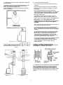
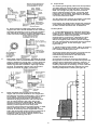
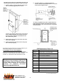
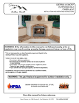
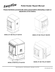
Shenandoah R65-E Wood & Coal
Burning Heater Manual (EPA Exempt)
Installation & Operating Instructions
Please read this entire manual before installation. Save these instructions.
GENERAL INFORMATION
C o n g ra tu lation s
on
yo u r
p u rc h a s e
of
th e
Sierra/Shenandoah Heater. W e are confident that your new
stove will provide you with years of safe, com fortable and
efficient heating.
This m anual describes the installation and operation of the
Shenandoah R-65E coal heater.
Please read this entire m anual before you install and use
your new room heater. Failure to follow instructions m ay
result in property dam age, bodily injury, or even death.
Save these instructions for future reference.
SAFETY NOTICE
If this appliance is not properly installed, a house fire m ay
result. For your safety, follow the installation instructions.
Check with local building or fire officials about restrictions and
installation inspection requirem ents in your area.
It is best to have a professional install your Sierra Stove. If
you prefer to install it yourself (see Installation Instructions),
be sure to obtain the proper perm its. Have the local building
officials inspect the stove and chim ney pipe for safety and
code com pliance after the installation is
com plete.
<
<
<
<
SAFETY NOTICE
CAUTION: HOT W HILE IN OPERATION. KEEP
CHILDREN, CLOTHING AND FURNITURE AW AY.
CONTACT M AY CAUSE SKIN BURNS.
IF THIS HEATER IS NOT PROPERLY INSTALLED,
A HOUSE FIRE M AY RESULT.
CONTACT LOCAL BUILDING OFFICIALS ABOUT
RESTRICTIONS AND INSTALLATION INSPECTION
REQUIREM ENTS IN YOUR AREA.
FAILURE TO COM PLY W ITH OW NERS' M ANUAL
INSTRUCTIONS W ILL VOID YOUR W ARRANTY!
FAILURE TO FOLLOW INSTRUCTIONS M AY
RESULT IN PROPERTY DAM AGE, BODILY INJURY,
NOT APPROVED FOR M OBILE HOM ES.
DO NOT USE CHEM ICALS OR FLUIDS TO START
THE FIRE!
DO NOT BURN GARBAGE OR FLAM M ABLE FLUIDS.
DO NOT CONNECT TO ANY AIR DISTRIBUTION
DUCT OR SYSTEM
DO NOT CONNECT THIS APPLIANCE TO A CHIM NEY
FLUE SERVING ANOTHER APPLIANCE.
ALL SHENANDOAH SOLID FUEL ROOM HEATERS
HAVE BEEN TESTED IN ACCORDANCE W ITH
U.L.TEST STANDARD 1482-1998 TEST STANDARD
PLEASE LEAVE THIS MANUAL WITH THE OWNER !!
Listed by Warnock Hersey
INSTALLATION INSTRUCTIONS
• Installing a w ood or coral heater is different than
other fuel burning appliances.
2.
IF APPROVED FLOOR PROTECTION IS NOT
USED: Use the follow ing calculation to
determine if a proposed alternate floor
protector meets the requirements listed in the
appliance manual.
• Failure to install correctly could result in a serious
fire with loss of life and property.
a.
These instructions are to be used in conjunction
w ith the fire codes and ordinances for your specific
area which can be obtained from your local
building inspector for Fire M arshall. If required, the
proper perm it m ust be obtained! To protect your
family and property, you should determine the
applicable codes and ordinances and strictly
adhere to them.
Convert specification to R-value.
i. R-value is given – no conversion is needed.
ii. K-factor is given with a required thickness
(T) in inches: R = 1/k x T
iii. C-factor is given: r = 1/C
b.
Determine the R-value of the proposed
alternate floor protector.
i.
Use the formula in step (a) to convert
values not expressed as ”R”.
ii. For multiple layers, add R-values of each
layer to determine the overall R value.
A proper draft is absolutely essential to achieve
satisfactory performance.
c. If the overall R-value of the system is greater
than the R-value of the specified floor
protector, the alternate is acceptable..
• Too little draft will cause poor burning and
smoking.
Example:
The specified floor protector should be ¾ inch
thick material with a K-factor of 0.84. The
proposed alternate is 4” brick with a C-factor of
1.25 over 1/8” mineral board with a K-factor of
0.29.
• Too high a draft will cause the unit to burn too hot
and use excessive fuel.
• The draft reading should be from .04 to .07 inches
of w ater column (.06 W .C. is the desired draft). It
is the responsibility of the user to obtain the
proper draft range.
Step (a.) Use the formula above to convert
specification to R-value.
R = 1/k x T = 1/0.84 x .75 = 0.893
Step (b.) Calculate R of proposed system
4” brick of C= 1.25, therefore
R brick = 1/C = 1/1.25 = 0.80
1/8”mineral board of k=0.29, therefore
R min.bd = 1/0.29 x0.125 = 0.431
Total R = Rbrick + Rmineral board =
0.8 + 0.431 = 1.231
Step (c.) Compare proposed system R of 1.231 to
specified R of 0.893. Since proposed
system R is greater than required, the
system is acceptable.
• Low draft conditions may be corrected by using a
larger flue pipe, shorter connector pipe, or
extending the chimney height.
• High draft conditions may be corrected by
installing a barometric damper.
• A qualified serviceman should be consulted of
correction of chimney draft.
A. CHOOSING A LOCATION
A central location is most desirable, how ever, the
minimum required run of pipe to the chimney
should be the deciding factor.
Definitions:
Thermal Conductance = C =
Shenandoah Heaters must use an approved
system for venting flue gases. Figures 2 - 5
indicate various methods.
Btu
=
(hr)(ft 2)( BF)
Thermal Conductance =
k =
Btu
=
W
=
(hr)(ft 2)( BF)
(m 2)( BK)
B. PRIOR TO INSTALLATION
W
(m 2)( BK)
Btu
(hr)(ft)( BF)
1.
Remove carton, crating and all packing
material from the heater.
Thermal Conductance = R = (ft 2)(hr)( BF) = (m 2)( BK)
Btu
W
2.
Fire the stove outdoors to cure the paint, and
burn off odor of oils and solvents used in
manufacturing. Could cause unpleasant odors
in the home.
3.
4. Keep combustibles at least three feet from the
heater. This includes furniture, magazine racks,
rugs, clothing and firew ood.
C. CLEARANCE FOR SHEANDOAH HEATERS (Floor
Protector)
1.
Do not install in closets or alcoves.
Do not dry clothes on or within three feet of the
heater, or store flammable liquids in the same room
as the heater.
SET THE HEATER ON A NON-COM BUSTIBLE
FLOOR PROTECTOR W ITH AN R-VALVE OF
1.0 OR LISTED FLOOR PROTECTION that
covers an area 8” larger than the heater on
three sides and extends 16” beyond the ash
and loading doors and under the chimney
connector 2” beyond each side.
M inimum clearances from combustible materials
w ithout protection:
M odel R65 ( See figure 1)
Sides Back Fuel Door
A
B
32"
26"
36"
2
Top
48"
Connector Pipe
18"
5. M inimum clearances from combustible materials
w ith protection:
D. Connector Pipe Installation
This connector pipe connects the heater to the
chimney.
The distances betw een the sides and/or back can be
reduced by placing an approved wall protection
panel over the combustible walls.
Consult NFPA 211 for reduced clearances allowed a
proper installation.
On Shenandoah heaters, this pipe should be at
least 6 inches in diameter, 24 gauge, or heavier,
black pipe.
It is recommended that connector pipes be
installed with the crimped end down, including the
section which goes into the heater collar. In this
w ay, any possible creosote form ation will drain
dow n the inside pipe.
(The R65-E comes equipped with a cast iron
damper in the flue collar. You may need to cut
slots in your stove pipe to fit over the damper rod.)
IM PORTANT: ALL PIPE JOINTS AND THE
CONNECTION TO THE HEATER COLLAR SHOULD
BE SECURED W ITH AT LEAST THREE M ETAL
SCREW S.
The connector pipe should be at least 18 inches or
more from combustible materials.
The connector pipe should be as straight and
short as possible (keeping minimum clearances in
mind). It should have no more than tw o 90 degree
elbow s.
The horizontal connectors are required by NFPA
(National Fire Protection Association) No.211 to
have at least ¼ inch rise to the linear foot. It
should be easily accessible for cleaning, and
should not pass through walls, floors or ceiling
w ithout being properly insulated for heat.
The connector pipe should not be installed outside
or through unheated inside areas because
condensation of hot gasses com ing in contact
w ith a cold pipe w ill cause rapid creosote
accumulations.
CHIM NEY CONNECTOR SYSTEM S AND
CLEARANCES FROM COM BUSTIBLE W ALLS FOR
RESIDENTIAL HEATING APPLIANCES
Figure 1
A. M inimum 3.5 inch thick brick masonry all framed
into combustible wall with a minimum of 12 inch
brick separation from clay liner to combustibles.
The fireclay liner shall run from outer surface of
brick to wall, but not beyond the inner surface of the
chimney flue liner and shall be firmly cemented in
place.
Figure 2
Figure 3
3
E. Proper Draft
The chimney draft greatly influences the operation.
Too little draft can cause smoke to puff from the
thermostat damper or from the door. To increase
draft: use a larger flue pipe, shorten connector
pipe or extend chimney height. Too much draft
could cause overheating. A barom etric damper
installed in the connector pipe close to the heater
can control excessive draft.
The flue area of the chimney should be a minimum
area equivalent to 6 inch diameter flue pipe.
If necessary, the draft can be checked by qualified
serviceman and should have a draft of .04 inches
of water colum n m inim um and .07 m aximum.
B. Solid insulated, listed factory-built chimney
length of the same inside diameter as the chimney
connector and having 1 inch or more of insulation
w ith a minimum 9 inches air space betw een the
outer wall of the chimney length and combustibles.
Chimney Draft
1. Factory Build Chimneys: M ust be listed type
HT per UL 103. NFPA No.211 requires factory built
chimneys to be listed and installed in accordance
w ith conditions of the listing and the
manufacturer’s instructions. NFPA No.211 also
requires the chimney to extend at least 3 feet
above the highest point where it passes through
the roof, and at least 2 feet higher than any portion
of a building within 10 feet of the pipe. (See
figures 2 & 3)
2. Brick Chimney with Thimble: When an existing
chimney is used be sure it is in good repair and
has a suitable chimney flue liner.
A solid fuel heater should not be connected to the
same chimney as other heating appliances.
Unsatisfactory performance can result from
variable or insufficient draft.
C.
Sheet steel chimney connector, minimum 24 gauge
in thickness with a ventilated thimble, minimum 24
gauge in thickness, having tw o 1 inch air channels,
separated from combustibles by a minimum of 6
inches of glass fiber insulation. Opening shall be
covered, and thimble support with a sheet steel
support, minimum 24 gauge in thickness.
D.
Solid insulated, listed, factory-built chimney
length, with an inside diameter 2 inch larger than
the chimney connector, and having 1 inch or more
of insulation. Serving as a pass-through for a
single wall sheet steel chimney connector of
minimum 24 gauge thickness, w ith a m inim um 2
inch air space betw een the outer wall of the
chimney section and combustibles. M inimum
length of a chimney section shall be 12 inches
chimney section spaced 1inch aw ay from
connector using sheet steel support plates on both
ends of chimney section. Opening shall be
covered, an chimney section supported on both
sides with sheet steel support securely fastened to
w all surface of minimum 24 gauge thickness.
Fasteners used to secure chimney section shall
not penetrate chimney flue liner.
A connector to masonry chimney shall extend
through the inner face or liner but not beyond, and
shall be firmly cemented to masonry chimney. A
thimble may be used to facilitate removal of the
chimney connector for cleaning, in which case the
thimble shall be permanently cemented in place
w ith high temperature cement (see figure 4).
Figure 4
4
3.
Brick Chimney w ith Fireplace: The heater can
be vented into the fireplace by sealing the
opening w ith noncombustible material and
material and extending the connector pipe into
the chimney dam per. Refer to your local codes
(see Figure 5).
B. Starting the Fire and Burning Techniques
Warning: Do not use gasoline, gasoline type
lantern fuel, kerosene, Charcoal lighter fluid or
similar liquids to start or ‘freshen up’ a fire in this
heater. Keep all such liquids well away from the
heater.
DO NOT BURN garbage, gasoline, naphtha, engine
oil or any flammable liquids or chemicals or burn
you stove without grates in place.
DO NOT IN ANYW AY CAUSE THE UNIT TO
OVER-FIRE BY OVERRIDING THE THERM OSTAT
CONTROL.
This is an unsafe operation of the unit and could
severely damage the unit as well as endanger your
home. For this reason, this type of operation
w ould invalidate the w arranty.
Burning W ood
To start a wood fire, place crumpled new spaper on
the grate and cover it with kindling wood in a criss
cross pattern. Then place larger sticks on top of
the kindling. Before lighting the paper, be sure the
thermostat control is on “HIGH” and the flue
damper is open.
After lighting, close the door and latch. Place
additional wood in the heater as desired after a fire
bed is established and adjust the dam per. Adjust
the thermostat from time to time until the desired
comfort is obtained. The bi-metal therm ostat w ill
automatically control the combustion air to the fire
thus m aintaining the desired heat output.
Burning W ood on a coal grate
Because this unit will burn either w ood or coal, a
cast iron grate has been use. In order for w ood to
burn efficiently an ash build-up of 1" to 2" should
be allowed to accumulate on the grate. This tends
to plug the holes and reduce air flow to the wood
so it doesn’t burn too quickly. Therefore, do not
shake the ashes dow n through the grate until the
build-up has occurred. The ashes also serve to
insulate the grate from the hot coals thus
extending the life of the grate.
Figure 5
Bi-metal Thermostat Control
Shenandoah Heaters are therm ostatically
controlled, but do need reasonable attention to
assure efficient and trouble free operation, The
thermostat controls the dam per providing an
increase or decrease in combustion air to the fire.
Adjustm ent for comfort is necessary.
Types of wood
Split dry hardw oods (20% moisture levels) is
recommended for the best perform ance. This will
produce 5,500 to 6,000 BTU per pound. A mixture
of green and dry wood will produce satisfactorily.
W et and green wood will reduce the heat output of
the unit because the BTUH output is reduced by
the moisture content during the early stages of the
burn.
• Turn knob tow ard “HIGH” to increase heat output.
• Turn knob tow ard “LOW ” to decrease heat output.
A. Before building the first fire
1.
2.
3.
Com bustible materials must be kept at least
three feet from the stove. This includes
furniture, magazine racks, rugs, clothing and
firewood. Do not dry clothing or within three
feet of the heater, or store flammable liquids in
the same room with the heater.
Burn tim e
Depending on the type of wood (hard or soft) and
the bi-metal thermostat setting, a variable burn
time can be obtained. With a full firebox of
hardw ood at low setting, an overnight (8 to 10
hours) burn can norm ally be obtained.
Occasionally the movement and the handling
of the unit affects the bi metal thermostat and
dam per controls. Prior to building the firs fire,
check the operation of the therm ostat damper.
W ith a flashlight, shine light through the top of
the thermostat cover and observe the dam per
as the control knob is moved from low to high,
the damper must move freely and have no
hesitation in either the up or dow n movement.
If hesitation or sticking occurs, have the
thermostat corrected.
Adding w ood to the fire box
Check the grate operates to assure it is in
position and operates properly. Do not burn
the stove without the grates in place.
5
1.
Open smoke outlet damper. FULL OPEN.
2.
Open door slowly to allow air to move into the
firebox without creating a turbulence
3.
Check buildup under coals with poker, and if
tight, loosen up and force some ash into the
ash pan. This may also be done with the
shaker grate before wood is added.
4.
Place w ood on hot coals with small pieces at
the bottom .
5.
Close door and latch.
though some ash is desired to help keep the
grates cool, it is essential that ask is not allow ed to
block the air passage. If this occurs the fire will
cool dow n and may go out.
If fire bed is small, move the thermostat knob to
HIGH and fire will recover more quickly. Then
adjust to lower setting.
To sustain the fire bed, add fuel while the bed of
coals is hot. For normal operation add coals tw ice
per day, morning and evening.
If fire bed is large and hot, no adjustment to the
thermostat know is necessary.
Adjust the smoke outlet damper after the fire has
rekindled.
Adding Coal
A. Before building the first fire
C. Coal Burning
The techniques for burning coal are substantially
different from that required to burn wood. The
techniques likew ise vary for each installation and
for different heater designs.
Types of Coal
There are tw o recommended types of coal:
Bitum inous (soft coal), in either nut or stove size,
and Anthracite (hard coal), in nut size. There are
varying grades within each of these types
depending on the quality of the coal mined. Ash
yield is a factor to consider since low ash content
(8% or less) is desired.
As a result of varying qualities, specific burning
characteristics cannot be provided. How ever, it is
generally accepted soft coals have many of the
same burning characteristics as wood, requiring
similar air to fuel to ratios. Burning experience has
been excellent w ith soft coals. Some soft coals
have high sulfur content, and due to emission
cannot be burned in all locations.
1.
Open pipe damper.
2.
Open door.
3.
Check ash pan and remove ashes.
4.
Replace ash pan.
5.
Add 20-25 pounds of coal.
6.
Bank coal to top of firebrick in the back,
slightly heaping tow ard the center, then taper
toward the door opening.
7.
Leave some hot coals (6" square) exposed in
front to burn off gasses.
8.
Insert handle into grate and shake until hot
coals to fall into ash pan. A glow will appear in
the ash pan.
9.
Do not over shake grate.
10. Remove handle, close and latch door.
11. M ove the thermostat knob to HIGH setting for
approximately 15 minutes.
The Anthracite (hard coal) is a cleaner burning
product and yields an excellent fire. Experience
indicates that more attention is required for hard
coal fires and the temperature of the coal bed m ust
be maintained to assure desired performance.
12. A blue flame should appear over the top of the
fresh coal.
13. M ove thermostat to lower setting (to be
determined by experience).
Starting a Coal Fire
14. Close pipe damper.
To start a coal fire, follow the same procedure for
starting a wood fire. After the wood fire is burning,
add several small shovels of coal over the fire. As
the coal starts burn and glow, add more shovels in
small quantities until a glow ing coal bed is
established at a depth of 6 inch to 8 inches
tapering from the back toward the door. DO NOT
allow coal bed to go above fire brick lining.
Depending on the size of the fire box, 20-35 lbs of
coal should sustain the fire for approximately 12
hours. A fire can be maintained on a continuous
basis if given the necessary attention. If fire bed
cools too much betw een loadings, it may be
necessary to place som e kindling on the fire bed
prior to adding fresh coal to reduce the recovery
time.
After adding a large quantity of coal (15 lbs or
more) and w ith pipe dam per open, allow the heater
to operate on “HIGH” for approximately 15 minutes
to ignite the fresh fuel.
Immediately after fresh coal has been added, it is
normal that the heat output will drop until the fire
bed is re-established.
A blue flame should appear over the surface of the
coal bed. When this occurs, adjust the thermostat
to a lower setting and close the pipe damper.
Check fire periodically to assure that it is
spreading throughout the fuel bed.
Your stove has the cast iron outer grate with a
round center shaker grate, it will be necessary to
use a poker to work out ash from around the edge
of the fire bed next to the firebrick or the coals will
tend to go out. This can best be accomplished by
turning the end of a “L” shaped poker vertical with
the end pointing dow n. Insert along the side next
to the firebrick and move from front to back. To
remove ash from the area outside of the center
grate, insert the end of the poker up through the
grate from underneath the grate and w ork back
and forth through slots.
Burn Time (coal)
A properly controlled coal fire can burn for
extended lengths of time. Experience indicates
that from ¾ pounds to 5 pounds per hour can be
burned. In m ilder weather and w ith proper ash
control, 24 hour burn can be obtained. The fire
box can hold approximated 40 to 70 pounds of
coal depending on the model.
Remove ashes at least once a day while burning
continuously. Never allow ashes to build up in
grate.
Sustaining the Coal Fire
Burning Coal (Continued)
The efficiency and heat output of a coal fire is
directly affected by the air flow through the coal
bed and ash accum ulation on the grate. Even
Depending on the quality of coal used, it may be
necessary to periodically remove all un-burnable
6
material and ashes from the heater and start a new
fire. The fire should be allow ed to go out.
3.
DO NOT attempt to remove hot live coals.
4.
Each installation will vary slightly. Therefore, only
w ith experience can the best firing procedure be
determ ined.
5.
Opening the Fill Door
Chimney inspection and cleaning
M aking sure smoke outlet damper is FULL OPEN,
open the door ½ inch for 15 seconds before
opening it completely. This provides a slow
combustion of the accumulated gases above the
fire rather that a sudden burst of flame caused by
the introductions of oxygen. This will also allow
sm oke to move out of the heater more completely.
The chimney and heater should be inspected for
creosote buildup every tw o weeks during the
heating season. Creosote is recognizable as a
black oily or flaky deposit on the walls of the
heater and flue. If creosote has accumulated, it
should be removed to reduce the risk of a chimney
fire.
D. Ash Control and Removal
PERFORMANCE TIPS
For best results, shake dow n ashes until live coals
start to fall. Remove the ashes when the fir is low
prior to adding fuel. This should be done daily or
as often as required to avoid ash buildup.
A. If your heater SM OKES, has LOW HEAT
OUTPUT, or CANNOT M AINTAIN A FIRE, review
the following:
DO NOT allow ashes to build up to the grate level
as this will cause intense heat on the grate and
cause it to warp and have a short life. Inspect the
area around the ash pan and clean out as required.
1.
The chimney draft must be at least .04" W .C.
w ith .06" W .C. the recommended draft.
2. Clean creosote deposits from the chimney and
connector pipe.
3. The connector pipe from the heater to the
chimney may be too long. Reposition the
heater, if possible, for minimum clearances.
4. Do not have more than tw o 90 degree elbows
in the connector pipe.
5. Horizontal connector pipe must have 1/4" rise
per linear foot.
6. Use a chimney cap to reduce dow n drafts in
the chimney.
7. M ore than one heating appliance connected to
the sam e chimney flue can affect the draft.
8. Ash clean out at the chimney base must be
sealed with the door closed tightly.
9. Rem ove tree limbs that are too close to
chimney.
10. The chimney height may not be adequate for
proper draft. Increase height if necessary.
11. Burn small hot fires instead of heavily loaded
smoldering fires in mild weather.
12. Sufficient combustion air may not be available
to the heater. This can occur in some new ly
constructed highly insulated “light” houses.
Open a window I the room in w hich the heater
is located., If this helps, then outside air must
be piped to the damper area of the heater.
Consult your dealer for assistance.
For disposal of ashes, places ashes in m etal
container with a tight fitting lid. The closed
container of ashes should be placed on an
incombustible floor or on the ground, well away
from all combustible materials, pending final
disposal. If ashes are disposed of by burial in the
soil or otherw ise locally dispersed, they should be
retained in the closed container until all cinders
have thoroughly cooled.
DO NOT USE A PAPER BAG OR BOX.
E. Creosote & Soot Formation and Removal
W hen coal is burned, products of combustion
combine with moisture to form a soot residue
w hich accum ulates on the flue lining. W hen
ignited, this soot makes an extremely hot fire.
W hen wood is burned slowly, it produces tar and
other organic vapors which com bine w ith expelled
moisture to form creosote. The creosote vapors
condense in the relatively cool chimney flue of a
slow burning fire. As a result, creosote residue
accumulates on the flue lining, the connector pipe
and within the heater. W hen ignited, this creosote
makes an extremely hot fire.
B. Fire Burns Too Hot or Too Fast
If this happens, the fire department should be
called immediately. Extinguish the fire in the heater
by dumping a large quantity of coarse salt on the
fire, or by using a dry pow der to keep air from
entering the chimney. If possible, do not use water
to extinguish a chimney fire because it could
dam age the flue liner. If there is a major creosote
problem, have the chimney, stove pipe and heater
cleaned and inspected before firing the heater
again.
1.
2.
3.
4.
5.
6.
7.
In addition to being a fire hazard, the presence of
creosote will affect the performance by reducing
the draft. This may cause smoking from the fill
door or cause the inability to hold a fire.
8.
Check door gasket for proper seal.
Be sure knob is set to LOW setting.
Check combustion air damper. Be sure it is not
sticking open. (See section B under Operating
instructions)
For wood burning, allow ashes to build up on
grate.
Check chim ney draft - .07" W .C. maximum.
High winds or prevailing winds may cause
excessive draft.
Install a barom etric damper in pipe to reduce
drat.
Contact dealer for assistance.
C. Coal Fire Goes Out
The chimney connector and chimney should be
inspected at least once every tw o months during
the heating season to determine if a soot buildup
has occurred.
To reduce Creosote Problem :
1.
2.
Keep stack temperature above 250 degrees
Fahrenheit. Below 250 degrees Fahrenheit
produces black liquid creosote.
Rather than burn the heater extensively at a
low setting during the mild temperatures of 50
degrees and above, build a small hot fire for a
short period of time.
Install the heater with the connector pipes as
short as possible.
Use dry wood.
Burn a hot fire for approximately 30 minutes
daily.
7
1.
Check chimney draft. Should be no less than
.04" W .C. but .06" is recommended.
2.
Shake dow n ashes more frequently.
PERFORMANCE TIPS (continued)
3.
stores. Care should be taken to avoid damaging the
flue liner. Chimney cleaning service is available in
most areas.
Use poker with tip vertical and down to remove
ashes from the edges of the grate next to the
firebrick.
4.
Remove the ashes. Do not allow them to build
up under the grate in the ash pan.
5.
Keep pipe damper open until fire has rekindled.
6.
Check quality of coal being used. It must be
good quality with low ash yield.
7.
Adjust damper control knob for increased
combustion air.
8.
If wood has been burned previously, check
chimney for creosote buildup.
Clean as necessary.
9.
Chimney cap may be too restrictive.
D. Firebrick Inspection
At least once a year, check the condition of the
firebrick lining. All broken firebricks should be
replaced. New firebrick can be obtained from your
Shenandoah dealer.
SERVICE TIPS
(To be Performed Only by Qualified Installers)
Re-calibrating Thermostat Control
Note:
All calibration is done at approximately 70
degrees Fahrenheit
11. Fire bed m ay be too shallow . Hot fir bed m ust
be maintained at 6" depth or more.
The heat output of the stove is controlled by the
draft opening. This operates automatically by the
bimetal thermostat opening and closing the
damper plate. The normal temperature operating
range is preset at the factory.
12. Periodically add wood kindling with the coal to
reestablish the bed coal.
It is rare, but possible, for the operating range to
change after the heater is put into use.
10. M ay be using wrong size coal. Chestnut size is
recommended.
D. Heater M akes Noise
M etal cools off and contracts when it gets hot and
cools off. This may cause the heater to occasionally
give off some thumping and banging noises. The
noises should not be to a distractive level nor
reoccur w hile the heater is hot.
As wood burns, a log w ill often roll off the pile and
strike the side or front of the stove. It will create a
moderate thumping noise.
E. Unit W arps or Bow s Slightly
As metal expands under heat, it has to move. This
w ill tend to increase as the fire gets hotter. As the
heater cools off, the metal will return to near
original conditions. It is not abnormal or in any way
hazardous to have a minor change in m etal flatness
after having been heated.
The control should be re-calibrated for peak
performance as follow s:
MAINTENANCE INSTRUCTIONS
1.
Long life and perform ance of the heater is directly
related to proper maintenance. Please follow these
suggestions.
Turn control knob counter clockw ise until
pointer is against stop pin.
2.
Rem ove control knob from stem.
A. Summer Storage
3.
Turn stem until the damper plate is
completely closed.
4.
Turn stem clockw ise until dam per plate
starts to open.
5.
Replace know with the pointer directed to
Second indicator mark past LOW
(See Diagram above)
If the heater is rem oved during the off-season, store
it in a dry place to prevent rust. Before storing,
remove the ashes, clean, and touch up the paint
w here needed. A high temperature paint is available
from your dealer.
B. Yearly Flue Inspection
Each year before putting the heater into service, the
chimney flue should be cleaned of soot and other
residues, and inspected for needed repairs or any
accumulation of creosote. The inspection is in
addition to the bimonthly inspections during the
heating season.
SERVICE TIPS (Continued)
(To be Performed Only by Qualified Installers)
A. Door Adjustm ents
Occasionally it is desirable to improve its
operation or the seal betw een the door and frame.
This can result from minor changes due to normal
metal expansion after being subjected to heat.
C. Creosote Rem oval
Creosote should be removed from the chimney
using appropriate brushes and tools. These are
available through many stove dealers and hardw are
8
By determining the type of adjustment desired, the
follow ing procedure will make it simple and quick.
1.
4.
If door is tight on hinge side thus causing the
door to feel springy just prior to latch,
If neither steps 2 or 3 adjusts as desired,
loosen catch (2 bolts0 and position in or out as
required (see figure below)
To check for gasket seal, place a folded sheet of
paper betw een the door and frame with the door
shut. Pull paper to feel friction betw een the gasket
and door frame.
loosen hinge plates (2 bolts each) and allow to
move outw ard slightly. Do not allow to move
out far enough to lose the seal betw een the
door fram e and gasket.
2.
If Door latch opens and closes hard, tap door
catch dow n slightly.
3.
If door latch opens and closes too easily, tap
door catch up slightly.
By following the m anufacturer’s recom m endations your
Sierra Stove will give you years of service.
R65 Replacement Parts List
P/N
CONSUM ER PROTECTION W ARRANTY
Your Sierra Stove has a Lim ited Five-Year W arranty.
Please read it carefully, fill out the short registration form
and return it, within 30 days of purchase, to Sierra
Products, Inc., 5061 Brooks St. Ste. B Montclair, CA 91763.
Should you have a warranty claim on your
Sierra Stove, notify your nearest dealer, or
contact Sierra Products, Inc. at the above
address. For additional information
www.sierraproductsinc.net
Description
100045.1
Metallic Black Touch Up #3609
410079
Therm ostat Brass Rod R65/ 77
410080
Therm ostat Knob R65/77
410081
Flue Dam per R65/77
410082
Outer Grate Ring R65
410083
R65 Center Grate
410085
R65 Draw Bar/ Shaker
410086
Bi- Metal Therm o Spring R65/77
410088
Door Assem bly R65/77
410089
Door Gasket R65/77
410090
Door Handle Assy. R65/77
410096
Side Refractory Liner R65 Curved
P/N 140818 R65E MANUAL r1
Sierra Products, Inc.
5061 Brooks St. Ste B
M ontclair, CA 91763
9