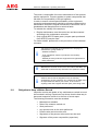
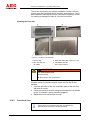
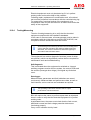
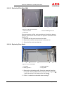
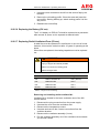
1
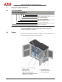
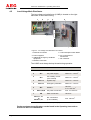
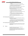
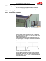
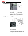
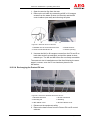
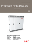
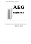
OPERATING INSTRUCTIONS
PROTECT PV.xxx-MH
Solar Inverter with Metal Housing
Medium Voltage
AEG Power Solutions GmbH, Warstein-Belecke
Department:
PS AE
Revision:
04
Revision date:
15/11/2013 / Hagelstein
Released:
15/11/2013 / Langer
Document no.:
8000043212_BAL_en
EN
Protect PV.500/630-MH - Operating Instructions
Revision Service
Page 2 of 45
Status
Revision
Date
Name
01
New edition
31/07/2012
Hagelstein
02
Corrections (pages 7, 10, 13)
15/10/2012
Hagelstein
03
Correction (pages 37/38)
30/10/2012
Hagelstein
04
supplementing PV.880-MH
15/11/2013
Hagelstein
8000043212 BAL
Protect PV.500/630-MH - Operating Instructions
Table of Contents
1
1.1
1.2
1.3
General Information .................................................... 5
Validity .......................................................................... 5
Appropriate Use ............................................................ 5
List of Abbreviations ...................................................... 5
2
2.1
2.2
Safety ........................................................................... 6
Installation Location....................................................... 6
Lightning Protection....................................................... 6
3
Scope of Delivery ........................................................ 7
4
4.1
4.2
4.3
4.4
4.5
Equipment Specifications........................................... 8
Type Designation .......................................................... 8
Design ........................................................................... 8
Dimensions ................................................................... 9
Ventilation ..................................................................... 9
Low-Voltage Main Distributor ...................................... 10
5
Functional Description.............................................. 11
6.
6.1
6.2
6.3
Transport ................................................................... 12
Transport Securing Device .......................................... 12
Crane Transport .......................................................... 13
Transport by Industrial Trucks ..................................... 14
7
7.1
7.2
7.3
7.3.1
7.3.2
7.3.3
7.3.4
7.4
Assembly ................................................................... 15
Foundation .................................................................. 15
MH Station .................................................................. 16
Installation ................................................................... 18
DC Connections .......................................................... 18
AC Connections .......................................................... 18
Power Supply .............................................................. 20
Communication Interfaces ........................................... 21
Tightening Torques for Screw Connections ................. 22
8
Start-up ...................................................................... 23
9
Operation ................................................................... 23
10
10.1
10.2
10.2.1
10.2.2
10.2.3
10.2.4
10.2.5
10.2.5.1
10.2.5.2
10.2.5.3
10.2.5.4
10.2.5.5
10.2.5.6
10.2.5.7
10.2.5.8
10.2.5.9
Maintenance .............................................................. 24
Obligation to Keep a Written Record ........................... 26
Service work and Inspection........................................ 27
Visual Inspection ......................................................... 27
Cleaning ...................................................................... 27
Functional Test............................................................ 28
Testing/Measuring ....................................................... 29
Care ............................................................................ 30
Lubrication .................................................................. 30
Replacing Filter Mats (PV.xxx) .................................... 30
Replacing Filter Mats (MH) .......................................... 31
Replacing Door Seals.................................................. 31
Replacing the Service Flap Seal.................................. 32
Replacing the Battery (PV.xxx) .................................... 33
Replacing Radial Ventilators/Fans (PV.xxx) ................ 33
Replacing Output Contactor K7 ................................... 34
Replacing Capacitors C86 and C87 ............................ 34
8000043212 BAL
Page 3 of 45
Protect PV.500/630-MH - Operating Instructions
10.3
10.3.1
10.3.2
10.3.2.1
10.3.2.2
10.3.2.3
10.3.2.4
10.4
10.5
Repairs........................................................................ 34
Testing after Repairs ................................................... 35
Exchanging Work ........................................................ 35
Exchanging the Door Stops ......................................... 35
Exchanging the LVMD Service Flap Opener ............... 36
Exchanging the Waste Air Duct ................................... 36
Exchanging the Protect PV.xxx ................................... 37
Period Schedule .......................................................... 39
Storing Spare Parts ..................................................... 41
11
11.1
11.2
11.3
11.3.1
11.3.2
Decommissioning and Dismantling ......................... 42
Removing Connection Cables ..................................... 42
Dismantling ................................................................. 42
Disposal ...................................................................... 43
Statutory Provisions .................................................... 43
Chemical System Components ................................... 43
List of Tables ............................................................................... 45
List of Figures ............................................................................. 45
AEG Power Solutions GmbH
Emil-Siepmann-Strasse 32
59581 Warstein
Germany
Fax:
+49 2902 763 100
+49 2902 763 645
E-mail: [email protected]
Internet: http://www.aegps.com
Page 4 of 45
8000043212 BAL
Protect PV.500/630-MH - Operating Instructions
1
General Information
1.1
Validity
These instructions relate to the technical specifications of the
equipment at the time of publication. These instructions are a
component part of the system.
Legal claims arising from this contractual relationship shall only be
recognised by AEG Power Solutions GmbH subject to the terms
agreed under the warranty obligation in the main contract.
1.2
Appropriate Use
The Protect PV.xxx-MH are compact, housed inverter stations with
power ratings of 500 until 880 kW respectively. The direct current
generated from the solar cells is converted into alternating current
for the mains supply.
The Protect PV.xxx is intended for outdoor installation. The AC is
fed into medium-voltage mains according to the local feed
conditions using an electrically isolated transformer located in the
compact station.
The equipment may only be used for this purpose. Any other use
constitutes misuse and can endanger personal safety.
1.3
List of Abbreviations
Abbreviation
Meaning
CS
Compact Station
MH
Metal Housing
Further information can be found in the Operating Instructions (BAL)
Protect PV.500 or PV.6x0/8x0-ID.
8000043212 BAL
Page 5 of 45
Protect PV.500/630-MH - Operating Instructions
2
Safety
The qualified skilled personnel are responsible for safety.
The member of personnel who is responsible for the equipment
must ensure that only suitably qualified persons are allowed
access to the equipment.
To ensure safety in the electrical operating areas, these areas
should be lockable; i.e. suitable locking systems should be
installed by the owner in all MH stations.
2.1
Installation Location
The equipment is intended for use outdoors as an enclosed
electrical unit.
• Environmental conditions: ( Technical Data) in accordance
with DIN EN IEC 60721-3-3.
• Freely accessible air vents for heat dissipation.
Cooling type F (DIN 41751).
• Ground pressure: min. 150 kN/m2.
Refer to the technical data for additional criteria.
When selecting the installation location, regional regulations
governing noise emissions must be taken into account.
Do not install the equipment in areas subject to flooding or those
with a high groundwater level.
2.2
Lightning Protection
The connection to the potential equalisation system provides the
equipment with effective protection against lightning strikes.
The manufacturer’s specifications must be implemented effectively
in order to provide the photovoltaic system with suitable lightning
protection measures.
Further information regarding safety can be found in the Operating Instructions
(BAL) Protect PV.500 or PV.6x0/8x0-ID.
Page 6 of 45
8000043212 BAL
Protect PV.500/630-MH - Operating Instructions
3
Scope of Delivery
Check that the following components have been delivered with the
equipment:
• 1x Protect PV.500/630-MH consisting of:
− Metal housing with built-in Protect PV.xxx
• Fastening material (brackets, bolts, heavy-duty dowels)
•
Technical documents comprising:
− Technical data
− Operating instructions
− Drawings/circuit diagrams
Optional
Depending on the equipment configuration, the following
components may or may not be included in the scope of delivery:
• Prefabricated foundation
Available to order
AEG Service can also provide the following documents:
• Spare parts list
• Service book
To place an order, please contact:
AEG Power Solutions GmbH
Emil-Siepmann-Strasse 32
59581 Warstein
Germany
Fax:
+49 2902 763 100
+49 2902 763 645
E-mail:
Internet:
[email protected]
http://www.aegps.com
8000043212 BAL
Page 7 of 45
Protect PV.500/630-MH - Operating Instructions
4
Equipment Specifications
4.1
Type Designation
Protect PV.690-MH-Vx-GER-x
x = option
GER = state/region/standard
Vx = version (optional)
MH = with metal housing
690 kW = nominal AC output
PV = photovoltaik series
Protect = AEG family
Table 1 - Type designation in accordance (example)
The type designation of the inverter can be found in the BAL
Protect PV.500 or PV.6x0/8x0.
4.2
Design
The Protect PV.xxx-MH comprises a DC/AC control cabinet and an
INV control cabinet within a metal housing.
1
3
2
4
5
6
Figure 1 - Protect PV.500/630-MH
1 Metal housing
2 Air outlet hood
3 INV control cabinet with
display and operation unit (DOU)
4 DC/AC control cabinet
Page 8 of 45
8000043212 BAL
5 Low-voltage main
distribution with Q26
6 Fastening bracket
Protect PV.500/630-MH - Operating Instructions
4.3
Dimensions
2
1
3
4
5
Figure 2 - Metal housing top view
Item
Dimension
MH height with roof
[mm]
2791.0
1
MH depth (roof)
1114.0 (1301.3)
2
MH width (roof)
3000.0 (3178.5)
3
DC cable feed-through
600 x 100
4
AC cable feed-through
440 x 100
5
Total depth when door is open
2570.0
Weather protection grid depth
76.0
Table 2 - Dimensions
4.4
Ventilation
The ventilation for the metal housing is based on the ventilation
concept for the Protect PV.xxx-ID.
The fresh air for ventilating the cabinet is drawn in through the
vents in the doors and discharged upwards via the radial fans into
an exhaust air duct/opening.
To avoid unnecessary increases in the room temperature inside
the metal housing, the mounting connection between the exhaust
air duct and the exhaust air opening must be as airtight as
possible.
The Protect PV.5x0/6x0 has two radial fans on the INV cabinet
roof. The PV.8x0 has an additional fan on the DC/AC cabinet.
The exhaust air duct and the exhaust air opening are
correspondingly wider.
The fresh air for cooling the IGBT INV stack is drawn in through
the (lower) vent on the rear by the radial fan M1, directed through
the ventilation duct past the heat sinks and discharged via the air
outlet and the service flap.
Air requirement
Technical Data.
8000043212 BAL
Page 9 of 45
Protect PV.500/630-MH - Operating Instructions
4.5
Low-Voltage Main Distributor
The low-voltage main distributor (LVMD) is located on the righthand side of the metal housing.
1
2
3
4
5
6
7
Figure 3 - Low-voltage main distributor PV.630-MH
1 Ethernet connection
2 Power supplies
3 Additional emergency shutdown
equipment
4 Modbus connection
5 Load interrupter switch Q26.n
6 AC connections to
transformer
7 PE conductor
The LVMD must always be kept closed during operation.
Item
Connection
1
2
2
Circuit
Note
X93
Ethernet
4 x 2 AWG 23/1
X11
AC power supply
NYM-J 3 x 1.5 mm
2
X13
AC auxiliary current
(max. 400 W)
NYM-J 3 x 1.5 mm
2
3
X33:1-2
System stop
NYM-J 3 x 1.5 mm
2
3
X33:3-4
Emergency off button
NYM-J 3 x 1.5 mm
2
4
X91
Modbus
Li2YCYv
2
4 x 2 x 0.5 mm
6
X26: U,V,W
AC power connection
max. 3 x 150 mm
7
PE
Earth connection
120 mm
DC connections
(in PV.500/630)
max. 185 mm
X41:1L+, 1Lto
X41:8L+, 8L-
2
2
2
Table 3 - Connection terminals, MH (example)
Further equipment specifications can be found in the Operating Instructions
Protect PV.500 or PV.6x0/8x0-ID.
Page 10 of 45
8000043212 BAL
Protect PV.500/630-MH - Operating Instructions
Functional Description
PV.IcX
PV.SuN
max. 1 to 8
optional
TKS-CS.1000
PV.LoG-MH
PV.IcX
Transformer
TransformerMonitoring
max. 1 to 8
PV.500-MH
=
~
PV.500-MH
=
PV.IcX
PV.SuN
max. 1 to 8
optional
Transfer station
Radio and ripple
control /
power utility
interface
~
TKS-CS.500
4 x relay
Energy meter
Switchgear
PV.ControL
PV.LoG-MH
Transformer
Internet
connection
TransformerMonitoring
5
CAN bus, max. 2 x 500 m
FO, ring max. 4 km
Modbus/RS485, max. 2 x 500 m
Ethernet/COM server, max. 80 m
Power cable
RS485/current-voltage transformer
PV.500-MH
=
~
Figure 4 - Equipment diagram, PV.500-MH (example)
A maximum of 8 combiner boxes (PV.IcX/ArrayGuard), in which up
to 16 PV modules have been grouped together beforehand, can
be connected to each Protect PV.xxx-MH.
The transformers are installed according to the required power in
the compact station (CS.500/1000, CS.630/1260, or
CS.800/1600).
The PV.Control or Skycontrol unit is adapted to the power station
capacity and the local feed conditions.
Further information regarding the functional description can be obtained from
the Operating Instructions Protect PV.500 or PV.6x0/8x0-ID and the
PV.components.
8000043212 BAL
Page 11 of 45
Protect PV.500/630-MH - Operating Instructions
6.
Transport
The Protect PV.xxx-MH consists of a compact housing which can
be transported by a forklift truck or crane and suitable loadcarrying equipment (traverse cross bars or crane grabs).
Select lifting gear and load-carrying equipment according to the
weight of the equipment ( Technical Data).
6.1
Transport Securing Device
i
Never lift the equipment by the transport securing device.
1
2
Figure 5 - Transport securing device
1 Transport securing device
2 Fixing bolt
Remove transport securing device before assembly and retain for
future transportation if necessary.
Page 12 of 45
8000043212 BAL
Protect PV.500/630-MH - Operating Instructions
6.2
Crane Transport
DANGER
Suspended loads during transport
Possibility of death or crushing.
Select lifting gear according to the total weight to be
transported.
Do not step under suspended loads.
Secure the danger zone.
Wear personal protective equipment.
Figure 6 - Crane transport with special traverse cross bar
Special traverse cross bars are used for transporting the
Protect PV.xxx-MH by crane.
8000043212 BAL
Page 13 of 45
Protect PV.500/630-MH - Operating Instructions
6.3
Transport by Industrial Trucks
DANGER
Toppling of cargo during transport by industrial trucks
Possibility of death or crushing.
Lift cargo under its centre of gravity.
Secure the cargo and danger zone.
Wear personal protective equipment.
Figure 7 - Transport by industrial trucks
The base structure includes openings for loading forks; these
match up with the MH station's centre of gravity.
Page 14 of 45
8000043212 BAL
Protect PV.500/630-MH - Operating Instructions
7
Assembly
DANGER
Suspended loads during transport
Possibility of death or crushing.
Select lifting gear according to the total weight to be
transported.
Do not step under suspended loads.
Secure the danger zone.
Wear personal protective equipment.
7.1
Foundation
The Protect PV.xxx-MH requires a frost-proof foundation with a
min. depth of 80 cm.
The foundation should be a 25 cm wide, transversely reinforced
continuous footing with openings for feeding the cable through on
the gable sides.
1
2
3
Figure 8 - Prefabricated foundation
1 Prefabricated foundation
2 Cable feed-through
3 Transport anchor M18
The owner is responsible for building the foundation. A
prefabricated foundation may be used as an option.
M18 eye bolts must be removed from the prefabricated
foundation's anchors after transportation/assembly.
8000043212 BAL
Page 15 of 45
Protect PV.500/630-MH - Operating Instructions
7.2
MH Station
Before assembling the MH station, lead the cables to the
installation location on the DC and AC sides and position them
within the foundation so that they are ready to enter the station.
1
2
3
4
Figure 9 - Cable feed-throughs
1 Base structure
2 MH floor
3 DC cable feed-through
4 AC cable feed-through
When setting down the MH station, feed in the cables and avoid
crushing them under the base structure.
The MH station is screwed to the foundations to ensure its stability.
1
1
2
3
Figure 10 - Bracket assembly
1 Assembly brackets
2 Screws in bracket position
3 Anchor bolts
Holes (sealed with screws) are provided in the base structure at
the positions intended for brackets.
Page 16 of 45
8000043212 BAL
Protect PV.500/630-MH - Operating Instructions
Unscrew and remove the screws that are already there, position
the assembly brackets so that they are flush and screw them in
place using the relevant tightening torque.
Figure 11 - Hole for heavy-duty dowel
Drill the holes for the heavy-duty dowels in the completed
foundation.
The distance between the holes and the edge is specified by the
manufacturer of the heavy-duty dowels. For the M16 anchor bolts
supplied, it must be at least 80 mm to prevent cracks in the
concrete.
Fasten the assembly brackets to the relevant tightening torque
using the anchor bolts and spacers supplied.
8000043212 BAL
Page 17 of 45
Protect PV.500/630-MH - Operating Instructions
7.3
Installation
WARNING
Hinge side of the door when closing
Fingers or hands may be crushed.
Do not hold the hinge side of the door.
Take care while closing the cabinet door.
i
7.3.1
Observe the bending radius of the supply lines.
With one bend:
bending radius = 10 x diameter of supply line.
DC Connections
Establish the combiner boxes (PV.IcX/ArrayGuard)
DC connections in the Protect PV.500/630 DC/AC cabinet
( Operating Instructions Protect PV.500 or PV.6x0/8x0-ID and
electrical documents).
7.3.2
AC Connections
1
2
4
3
5
6
Figure 12 - PV.630-MH Low-voltage main distributor
1 Opening lever
2 Load interrupter switch Q26.n
3 AC connections from INV
Page 18 of 45
8000043212 BAL
4 Power supply, Modbus
and Ethernet
5 AC connections to transformer
6 PE conductor connection
Protect PV.500/630-MH - Operating Instructions
The opening lever for the LV main distributor is accessible when
the door to the inverter is open.
Insert the AC power connections from below and screw them to
the cable lug using the relevant tightening torque.
1
2
3
4
5
6
1
2
3
4
Figure 13 - PV.630-MH low-voltage connections
1 Connection L1 - X26:U
2 Connection L2 - X26:V
3 Connection L3 - X26:W
i
4 Connection - X26:PE
5 Load interrupter switch Q26.n
6 Protective cover (Makrolon)
The order of the conductors (L1, L2, L3) must be adhered to.
Establish AC power connections and PE connections in the
compact station in accordance with the circuit diagram and using
the relevant tightening torque.
Remove any cable debris and tools from the equipment and
replace the protective cover on the connection panel.
8000043212 BAL
Page 19 of 45
Protect PV.500/630-MH - Operating Instructions
7.3.3
Power Supply
1
2
Figure 14 - Power supply
1
X11:L, N, PE - 230 V AC power supply
2
X13:L, N, PE - Auxiliary power supply max. 400 W
The Protect PV.xxx-MH has a power supply for supplying internal
loads (fans) and an auxiliary power supply for the control unit.
Power is supplied from a second circuit or internally via the X3
connection (grid).
Page 20 of 45
8000043212 BAL
Protect PV.500/630-MH - Operating Instructions
7.3.4
Communication Interfaces
The Protect PV.xxx-MH has a variety of interfaces for monitoring
and control.
Data is exchanged with the PV.LoG via the Ethernet/COM server
and Modbus/RS485.
1
2
3
4
5
Figure 15 - Communication interfaces (example)
1
F93 - Overvoltage protection for Ethernet
2
F91 - Modbus surge voltage arrester
3
X93 - Ethernet connection
4
X33:1-2 - Additional system stop connection
4
X33:3-4 - Additional emergency off button connection
5
X91 - Modbus connection
The X33 interface allows the owner to install additional external
emergency shutdown equipment.
The PV.LoG data logger is installed in the connected compact
station.
Wiring is carried out in accordance with the circuit
diagram/overview diagram.
Data is exchanged between the PV.IcX combiner boxes and the
PV.LoG or PV.ControL via CAN bus ( *.USP and operating
instructions for PV.LoG and PV.ControL).
8000043212 BAL
Page 21 of 45
Protect PV.500/630-MH - Operating Instructions
7.4
Tightening Torques for Screw Connections
Mechanical connection
Electrical
connection
Cheese head screw,
strength category 5.8
Hexagon screw,
strength category 8.8
[Nm]
[Nm]
[Nm]
Slotted cheese head
screw
DIN 84 with slot
[Nm]
M4
1.2
1.3
2.0
1.2
M5
2.0
2.65
4.0
2.0
M6
3.0
4.4
7.0
2.5
M8
6.0
10.5
17.0
3.5
M10
10.0
-
33.0
4.0
M12
15.5
-
56.0
-
M16
30.0
-
140.0
-
M20
52.0
-
260.0
-
M24
80.0
-
445.0
-
Thread
Table 4 - Tightening torques
These values apply to electrical and mechanical screw
connections. They do not apply to floor attachment with dynamic
stress applied.
Page 22 of 45
8000043212 BAL
Protect PV.500/630-MH - Operating Instructions
8
Start-up
DANGER
Working with voltages up to 1 kV
Risk to life due to electric shock.
Comply with BGV A3, DIN VDE 0105-100
(EN 50110, IEC 61243).
Skilled personnel with a Working with Live Current
certificate.
i
The electrical equipment must not be started up/operated if
there are any traces of condensation.
Starting up the Protect PV.xxx-MH correctly for the first time
assumes that all the components in the solar power station have
been correctly installed, wired and earthed. When starting up for
the first time, the equipment owner must obtain authorisation to
work with switchgear for the purposes of connecting the transfer
station, and must tell the local grid operator when the connection
will occur.
Instructions: Requirements for Start-Up
of AEG PV Inverter(s)/Station(s).
Instructions: Requirements for Start-Up
of PV Powerplant Monitoring.
Equipment information for start-up from Skytron
Once the requirements have been fulfilled and all assembler
certificates and test reports for the PV power station are present,
the person carrying out the initial start-up checks that they are
complete and accurate. For legal reasons, this person is obligated
to check all components and values again in accordance with the
start-up log, and to document the results.
Special AEG PS software and hardware tools are required for
initial start-up; therefore, it is recommended that AEG PS service
personnel carry out the initial start-up process.
Skilled personnel working for the equipment owner are only in a
position to use these tools correctly and to perform initial start-up
correctly once they have been trained in this area.
Further information regarding start-up can be found in Installation and Start-up
(BAL) Protect PV.500 or operating instructions PV.6x0/8x0-ID
9
Operation
All information regarding operation can be found in the Operating Instructions
Protect PV.500 or PV.6x0/8x0-ID.
8000043212 BAL
Page 23 of 45
Protect PV.500/630-MH - Operating Instructions
10
Maintenance
DANGER
Contact with voltage
Risk to life due to electric shock.
Press emergency off.
Move the victim away from live parts using dry insulating
material.
Get medical help and inform the control room.
Disconnect the equipment safely.
DANGER
Working with voltages up to 1 kV
Risk to life due to electric shock.
Comply with BGV A3, DIN VDE 0105-100
(EN 50110, IEC 61243).
Skilled personnel with a Working with Live Current
certificate.
DANGER
Residual voltage from capacitors
Risk to life due to electric shock.
Observe discharge time.
Disconnect the equipment safely.
i
Keep the equipment clean to minimise leakage currents.
DANGER
Contact with leakage current
Risk to life due to electric shock.
Disconnect the equipment safely.
DANGER
Toppling of cargo during transport by industrial trucks
Possibility of death or crushing.
Lift cargo under its centre of gravity.
Secure the cargo and danger zone.
Wear personal protective equipment.
Page 24 of 45
8000043212 BAL
Protect PV.500/630-MH - Operating Instructions
CAUTION
Insufficient ventilation of equipment
Equipment may overheat.
Keep air vents clear.
Ensure the equipment is sufficiently ventilated.
WARNING
Heat generation in resistors
Risk of burning.
Do not touch hot components.
WARNING
Hinge side of the door when closing
Fingers or hands may be crushed.
Do not hold the hinge side of the door.
Take care while closing the cabinet door.
WARNING
Entry of water into electrical equipment
Risk to life due to electric shock.
Do not use water to clean the cabinets.
Do not place any vessels containing fluids (beverage cups,
for example) on electrical equipment.
5 safety rules
1. Disconnect safely.
2. Secure the equipment against being switched back on.
3. Verify that all poles are de-energised.
4. Earth the equipment, close the earthing switch and shortcircuit the equipment.
5. Provide protection in the form of covers or barriers
for any neighbouring live parts.
i
A safe disconnection certificate or a release certificate
according to DIN VDE 0105-100 (EN 50110) must be
presented prior to all maintenance and repair work.
i
The owner must draw up a safe disconnection procedure and
brief personnel on this.
8000043212 BAL
Page 25 of 45
Protect PV.500/630-MH - Operating Instructions
The owner is responsible for correct maintenance of the systems
and the equipment. This also applies to system components that
fall within the responsibility of the grid operator.
In order to ensure uninterrupted availability of the equipment,
preventive maintenance work should be carried out based on the
maintenance schedule. Regular maintenance reduces the risk of
breakdowns and disruption due to technical faults.
To maintain the validity of the warranty:
• Regular maintenance must be carried out and documented
according to the maintenance schedule.
• Only original AEG PS spare parts (or spare parts purchased
from AEG PS) may be used.
For further details, please refer to the provisions of the individual
contracts.
The owner must define work instructions for carrying out
maintenance, giving details of:
i
- Ambient conditions
- Tools, equipment, means of protection and auxiliary
equipment
- Suitable personal protective equipment and organisational
safety measures.
10.1
i
Maintenance must be carried out in accordance with BGV A3
(DIN VDE 0100/VDE 0105) and DIN 31051 (DIN EN 13306).
i
AEG PS will rescind all obligations such as warranty
agreements, service contracts, etc. entered into by AEG PS or
its representatives without prior notice, in the event of
anything other than original AEG PS spare parts being used.
Obligation to Keep a Written Record
Inspection results and details of any maintenance carried out must
be recorded in writing. Experience has shown that the best way to
document inspection results is in the form of a test report.
The following information must be recorded:
• Maintenance schedule
• Date of the measure carried out
• Work performed
• Any special notes on the work performed
• Persons who carried out the work
• Signatures of the persons who carried out the work
• Signature of the person responsible (supervisor)
Page 26 of 45
8000043212 BAL
Protect PV.500/630-MH - Operating Instructions
A correct test report, completed in full, is important for technicians
as evidence of exoneration in case of later complaints or for
investigations in case of damage. For this reason, test reports
should be retained for a long time (around 10 years).
10.2
Service work and Inspection
10.2.1
Visual Inspection
Visual inspections should be carried out in accordance with
DIN EN 13018.
Inspections must involve careful checks for the following in the
equipment:
• Mechanical damage
• Corrosion, thermal changes to and tightness of the
electrical connections
• Defective fuses
• Foreign bodies
• Fans dirty or damaged (M2 to M3/4 when the waste air
duct is open)
• Filter mat dirty or damaged
• Moisture
• Accumulation of conductive dirt or dust
Safety devices and warning notices should be checked for damage
and legibility.
If there is condensation in the equipment, the internal heating
device should be checked to determine whether it is working
properly.
10.2.2
Cleaning
i
Only equipment tested in accordance with DIN VDE 0680 may
be used for cleaning.
i
If there is condensation in the equipment parts that are to be
cleaned, cleaning must not be carried out.
The cleaning procedure used must comply with the relevant
regulations and provisions of the accident prevention regulation
VBG 4 "Elektrische Anlagen und Betriebsmittel" (Electrical
installations and equipment) and DIN VDE 0105-100 (Operation of
electrical installations). Only specially trained electricians may
carry out cleaning work when the equipment is live.
8000043212 BAL
Page 27 of 45
Protect PV.500/630-MH - Operating Instructions
The log for dry-cleaning low-voltage installations using a vacuum
cleaner must be completed before and after cleaning work. Circuit
and installation markings should be noted before cleaning, so that
if a marking is damaged or falls off, this can be rectified.
Cleaning the heat sink
1
2
2
3
4
4
3
Figure 16 - Protect PV.xxx heat sink
1 Service flap
2 INV rear wall with
air outlets
3 Heat sink IGBT INV stacks (A1, A2)
4 Ventilation duct M1
INV control cabinet
WARNING
Hot surfaces/heat sink
Risk of burning.
Do not touch hot components.
Unscrew screw connections and lift out the service flap by the
handles.
1. Unscrew and remove the two accessible parts of the INV rear
wall with air outlets.
2. Clean the heat sink carefully using compressed air from bottom
to top, for example. (Wear protective goggles.)
3. Replace the rear wall and service flap.
10.2.3
Functional Test
i
Page 28 of 45
Always perform a functional test after completing any
servicing work and before starting operation.
8000043212 BAL
Protect PV.500/630-MH - Operating Instructions
Electrical equipment must only be started up if it is in perfect
working order and must be kept in this condition.
Following repair, replacement or modification work, a functional
test must be performed in accordance with the commissioning log.
For repeat tests, functional testing of the equipment or its
components need only be carried out to an extent that verifies the
safety of the equipment.
10.2.4
Testing/Measuring
The aim of testing/measuring is to verify that the electrical
equipment complies with the installation standards.
In the case of recurrent tests, all measurements must be taken in
accordance with the initial start-up and DIN VDE 0105100, and
compliance with all values/limits must be verified.
i
All measuring and monitoring devices used for testing must
comply with the standards DIN VDE 0413/EN 61557 and
DIN 0404, and must be tested and calibrated regularly in
accordance with ISO 9001:2000.
The equipment has various diagnostic functions (some of which
are optional), which can significantly reduce the time required for
maintenance work and troubleshooting.
Self-diagnosis:
This is activated when the equipment is switched on. Internal
auxiliary programs monitor the bus system, the control PCBs and
the sensors (amongst other things), and signal any faults that
occur.
Data logger:
Measured data, parameters and fault indications are saved
continuously. Measured data and performance data, as well as
fault histories, can be read out and evaluated as required.
i
The operating instructions describe how to output
performance and fault histories.
BGV A2 requires the owner to perform repeat tests at stipulated
times in order to verify that the electrical equipment is in perfect
working order.
At stipulated times, the owner must check that the fault current,
differential current and fault voltage protection devices are
functioning properly.
Carry out an insulation test by hand.
8000043212 BAL
Page 29 of 45
Protect PV.500/630-MH - Operating Instructions
10.2.5
Care
10.2.5.1 Lubrication
Carry out the following care measures for the station:
• Lubricate hinges, rods and guide rails after cleaning.
• After cleaning rubber door seals, rub lightly with a rubber care
product such as deer tallow.
• Clean weather protection grid seals and rub with a rubber care
product. When dismantling the weather protection grid, carry
out care measures for the entire seal.
10.2.5.2 Replacing Filter Mats (PV.xxx)
1
2
Figure 17 - Filter mat PV-xxx
1 Filter mat
2 Protective grid
In accordance with DIN EN 779, CTM 60 air filter mats must be
replaced annually.
1. Unscrew the protective grid.
2. Remove the old filter mat and screw in the new one.
3. Screw the protective grid back on.
Page 30 of 45
8000043212 BAL
Protect PV.500/630-MH - Operating Instructions
10.2.5.3 Replacing Filter Mats (MH)
1
2
3
3
4
Figure 18 - Filter mat in MH station
1 Filter mat insert
2 Filter mat
3 Screw fastening M5 x 12
Clean and replace air filter mats according to the pollution degree;
however, this must be done at least one a year in accordance with
DIN EN 779.
1. Unscrew the filter mat insert from the inside.
2. Remove the old filter mat and screw in the new one.
3. Screw the filter mat insert back on.
10.2.5.4 Replacing Door Seals
1
2
3
2
4
Figure 19 - Door in MH station
1 Lock side
2 Sealing profile 1
3 Sealing profile 2
4 Hinge side
1. Remove the old sealing profile. Clean the area and insert the
new profile. Starting with profile 2 at the top of the hinge side
, attach the seal up to the edge of the lock side .
2. Profile 1 is attached underneath these markings.
8000043212 BAL
Page 31 of 45
Protect PV.500/630-MH - Operating Instructions
Sealing profile 1
Selected material for sealing profile
Sponge rubber (EPDM) black (rubber section EPDM 65° ± 5 Shore A)
Sponge rubber (NBR) black (rubber section NBR 60° ± 5 Shore A)
Sealing profile 2
Selected material for sealing profile
Sponge rubber (EPDM) black (rubber section EPDM 65° ± 5 Shore A)
10.2.5.5 Replacing the Service Flap Seal
1
2
3
4
5
Figure 20 - Service flap in MH station
1 Weather protection grid
2 Service flap
3 Screw connection
Page 32 of 45
8000043212 BAL
4 Sealing profile
5 Air outlet
6 Waste air duct
6
Protect PV.500/630-MH - Operating Instructions
1. Unscrew screw connections and lift out the service flap by the
handles.
2. Remove the old sealing profile. Clean the area and insert the
new profile. Starting halfway up, attach sealing profile 2 all the
way round.
3. Reattach the service flap.
10.2.5.6 Replacing the Battery (PV.xxx)
The 3 V Li-battery on PCB A17 should be replaced as a precaution
after around 10 years, as it is exposed to thermal loads.
10.2.5.7 Replacing Radial Ventilators/Fans (PV.xxx)
A radial fan must be replaced if it is defective or runs out of round;
however, this must be carried out after 10 years of operating at the
latest.
When fans are replaced, the starting capacitors must be replaced
too.
WARNING
Rotating parts
Injury to fingers and hands possible.
Do not reach into rotating parts.
De-energise fans.
Cabinet
Component
Plug
INV
Radial ventilator M1
X201 (DC/AC)
INV
Radial fan M2
A91.2
INV
Radial fan M3
A91.3
DC/AC
Radial fan M4
A91.4
Table 5 - Plugs for fan monitoring
Removing and installing radial ventilator M1:
Ventilator M1 is located in the lower ventilation duct of the INV
control cabinet.
1. Disconnect the plug connection from the power supply.
2. Unscrew the cover from the ventilation duct.
3. Disconnect the temperature sensor.
4. Unscrew and remove the 6 screw connections from the
ventilator bracket.
5. Disconnect the ventilator assembly (2 nuts).
6. Pull the ventilator assembly out of the ventilation duct towards
you and set it down.
8000043212 BAL
Page 33 of 45
Protect PV.500/630-MH - Operating Instructions
7. Disconnect and remove the connection cables from the
ventilator.
8. Clean the inside of the ventilation duct. Clean the cooling fins
of the IGBT inverter stacks with compressed air.
Installation is the same procedure in reverse.
Switch on the equipment and test whether the ventilator is working.
Removing and installing radial fans M2 and M3/4:
Fans M2 and M3/4, and their corresponding connectors, are
located on the INV cabinet roof.
1. Unscrew the service opening or dismantle the waste air duct.
2. Remove fan connectors X91.2 X91.3 and X91.4.
3. Unscrew the screw connections from the cable clip.
4. Unscrew and remove the screw connections from the mounting
plate.
5. Lift the fan plus the mounting plate from the cabinet.
6. Unscrew the fan from its mounting plate and remove it.
7. Disconnect and remove the connection cables from the fan.
Installation is the same procedure in reverse.
Switch on the equipment and test whether the fan is working.
10.2.5.8 Replacing Output Contactor K7
The life span of a 3-pin contactor is determined by the number of
operating cycles it engages in:
• Electrical service life 440 V approx. 200,000 operating cycles
• Mechanical service life approx. 500,000 operating cycles
The operating cycles are recorded in the memory and indicate
when the contactor should be replaced. The electrical service life
can be extended by replacing the coil.
10.2.5.9 Replacing Capacitors C86 and C87
The capacitors in front of the IGBT inverter stacks have a life span
of approx. 100,000 operating hours and should be replaced when
this is reached.
10.3
Repairs
Only AEG PS skilled personnel may carry out repairs and
modifications on the Protect PV.xxx-MH.
If you want other personnel to carry out this work, this will need to
be authorised by means of written approval from AEG PS.
Only original AEG PS spare parts (or spare parts purchased from
AEG PS) may be used.
Page 34 of 45
8000043212 BAL
Protect PV.500/630-MH - Operating Instructions
10.3.1
Testing after Repairs
Each time the equipment is repaired or modified, all recurrent
tests/measurements are to be carried out and documented in
accordance with DIN VDE 0105 once the work is complete.
10.3.2
Exchanging Work
10.3.2.1 Exchanging the Door Stops
1
2
3
4
5
6
Figure 21 - Door stop in MH station
1 Screw connection
2 Door stop arm
3 Release
4 Guide rail
5 Earthing clip
6 Filter insert frame
The doors can be opened to a maximum of 95°. In this case the
door opening clearance is approx. 2670 mm, which means it is not
possible to replace the PV.xxx.
To remove the door stop, remove the screw connection M8 x 20
from the frame beam of the housing. This means the door stop is
now only connected to the door panel, and the door can be
opened to a sufficient extent.
Figure 22 - Opening with and without door stop
The open passage between the doors can also be increased by
unscrewing the earthing clips from the door frame and removing
the filter mat inserts. To do this, all M5 x 12 hexagon screws must
be removed from the frame.
8000043212 BAL
Page 35 of 45
Protect PV.500/630-MH - Operating Instructions
10.3.2.2 Exchanging the LVMD Service Flap Opener
1
2
3
4
Figure 23 - LVMD opener
1 Opening lever
2 Screw connection
3 LVMD service flap
4 Release mechanism
The LVMD service flap opening lever reduces the frame width by
about 42 mm. For this reason, the lever should be dismantled as a
precaution when replacing the PV.xxx. To do this, the two
M5 x 20 countersunk screws and the lever must be removed.
Installation is the same procedure in reverse.
10.3.2.3 Exchanging the Waste Air Duct
1
2
4
3
2
2
3
4
5
6
Figure 24 - Air outlet conduit PV.5x0/6x0
1 Detailed view of connection
from rear
2 Screw connection M5 x 12
3 Screw connection M16 x 40
4 Air baffle
5 Fans M2 and M3
6 INV control cabinet
The Protect PV.8x0 is equipped with an additional fan M4 on the
top of the cabinet DC/AC. The fan cover of the PV.8x0 is been
corresponding longer and enclosed this fan.
Page 36 of 45
8000043212 BAL
Protect PV.500/630-MH - Operating Instructions
1. Open the service flap from the rear.
2. Remove the air baffle by unscrewing all M5 x 12 hexagon
screws from the waste air duct (on the side) and the INV
control cabinet (rear wall) and removing the plate.
1
2
3
4
Figure 25 - Waste air duct from the front
1 Detailed view of connection from front
2 Screw connection M16 x 40
3 Waste air duct
4 Service opening
3. Unscrew the M16 x 40 hexagon screws from the PV.xxx-ID on
both sides at the front and back, and pull the waste air duct
towards you. The M2 and M3/4 fans are now freely accessible.
The waste air duct is installed around the fans following the same
steps in reverse, once the PV.xxx has been placed in the
MH station.
10.3.2.4 Exchanging the Protect PV.xxx
1
2
3
4
5
6
Figure 26 - Remove to dismantle the Protect PV.xxx
1 MH base structure
2 Mounting rail
3 INV cabinet cover
4 Screw connection
5 Earthing
6 DC/AC cabinet cover
1. Disconnect the equipment safely.
2. Remove the base covers from the Protect PV.xxx-ID control
cabinets.
8000043212 BAL
Page 37 of 45
Protect PV.500/630-MH - Operating Instructions
3. Remove DC connections and PE cables.
4. Remove PV.xxx-ID AC connections and PE cables in the lowvoltage main distribution (top).
5. Disconnect and remove the power supply, emergency
shutdown and communication connections from the PV.xxx-ID.
6. Secure the cables in the equipment.
1
2
3
Figure 27 - Dismantling the Protect PV.5x0/6x0
Z (M1:1)
Z (M1:1)
Sechskantschraube M12 x 30
M12 x 30 hexagon screw
Scheibe A12
A12 washer
1 MH base structure
2 MH mounting rail
3 M12 x 30 screw connection
7. Unscrew and remove all M12 x 30 hexagon screws fastening
the equipment in place. For the screw connections at the rear,
you may need to use a tool extension.
8. Push the forks of a telescopic loader into the openings in the
base structure underneath the equipment, lift gently and
reverse with caution. Always keep the equipment vertical when
lifting and do not tilt.
To coordinate the positioning and insertion of the PV.xxx-ID in the
MH station from the rear, the service flap in the rear wall should be
opened.
Pay attention to the earth connection when lifting the equipment in
and out.
Installation is the same procedure in reverse.
Page 38 of 45
8000043212 BAL
Protect PV.500/630-MH - Operating Instructions
10.4
Period Schedule
The period schedule does not release the owner from his
obligation to create his own maintenance and operating
instructions for the location and to document them fully as quickly
as possible.
i
For recurrent measurements and measurements after repair
work as per BGV A3, compliance with the DIN VDE 0105-100
inspection intervals is mandatory.
Ongoing
Check the measured results of the equipment for plausibility.
Replace defective measuring instrumentation at the end of production.
Data bus:
Ongoing functional testing in operation.
Monthly
Test lamps and replace diodes if required.
Check the function of the system's internal measuring instrumentation
by comparing the values during operation with the values displayed.
Check the function of the measuring instruments and accessory
systems required for operation and servicing.
Check the interior area and equipment for moisture and, if necessary,
establish the cause and dry the equipment.
Check door seals for dirt and damage and service or replace if
necessary.
Check the radial ventilators/fans in the cabinet ventilation system for
working correctly.
Replace defective ventilators/fans.
Clean the weather protection grid and ventilation grid from the outside.
MH station ventilation:
Depending on the pollution degree, clean or replace air inlet filter mats.
Clean interior of MH station (operating area).
Every 6 months
Check the fastenings and function of the electrical connections in the
MH station.
Check the fastenings and function of the electrical connections in the
equipment.
Check the function of the fault current, differential current and fault
voltage protective circuits.
Carry out recurrent measurements in accordance with DIN VDE 0105.
Cabinet ventilation:
Depending on the pollution degree, clean or replace air inlet filter mats.
Clean the heat sink of the IGBT INV stacks (A1, A2).
Check radial ventilators/fans for damage and whether they are working
correctly (rotation), and repair or replace if necessary.
8000043212 BAL
Page 39 of 45
Protect PV.500/630-MH - Operating Instructions
Every 6 months
Clean radial ventilators/fans.
(Do not use any cleaning products containing acids, bases or solvents
or water jets/pressure washers when cleaning).
Check the function of the heating devices (BG20) in the DC/AC and
INV control cabinet, especially before cold spells.
No condensation may be present in the equipment during operation.
Check the function of the overtemperature warning system by opening
the sensor path.
Annually
Measuring and monitoring devices must comply with the VDE 0413
standard.
Check and calibrate all measuring instruments.
Check that the equipment as a whole is in perfect working order:
- Check housing for damage
- Check line connections for dirt and corrosion
- Check protective covers for damage and check their
fastenings
Check all input, monitoring and output values in the equipment and
also in interaction with the external control system. Check the control
behaviour of the equipment and readjust, correct or change the limit
values if required.
Check the function of the peripheral connections, i.e. all connections of
the various accessory systems, and repair them if required.
Check the inverter control and inverter function.
Replace filter mats, clean protective grid and holder.
Clean the equipment to minimise creepage currents (do not use water).
Comply with BGV A3, DIN VDE 0105-100 during this process.
Clean and service door seals, and replace if necessary.
Check that the safety signs are complete and legible, and replace if
required.
(Must be checked by an expert every 2 years.)
Check function of lighting in control cabinet and housing, and replace if
necessary.
Every 2 years
Check of the safety signs in the operating area and in the equipment
by an expert.
Every 10 years
Exchange radial ventilators/fans in equipment ventilation system and
clean ventilation duct and cooling fins.
Exchange 3 V lithium battery on PCB A17 (INV).
Exchange starting capacitors.
Exchange output contactor K7 coils.
Page 40 of 45
8000043212 BAL
Protect PV.500/630-MH - Operating Instructions
10.5
Storing Spare Parts
i
When ordering spare parts, you must provide the component
designation, installation location and component number as
well as the unit number of the Protect PV.xxx-ID.
AEG PS recommends that you have the following spare parts
available:
Item
Component
F41.x
DC input fuses,
l.v. h.b.c. fuse L2-2 1200 V
A12, A13 (optional)
Remote signalling P8 - CCC
A91.1
Fan monitoring
M1
Radial ventilator (IGBT inverter stack)
M2, M3 (M4)
Radial fan (control cabinet)
K7
AC output contactor
Foam rubber seals (profile 1 and 2)
Table 6 - Spare parts
The AEG PS customer service department will be happy to send
you a complete spare parts list on request.
8000043212 BAL
Page 41 of 45
Protect PV.500/630-MH - Operating Instructions
11
Decommissioning and Dismantling
The Protect PV-xxx-MH can be decommissioned or dismantled for
the purposes of changing its location or disposal.
Before beginning any work on the equipment, it must be deenergised. For this purpose, the five safety rules of electrical
engineering in accordance with DIN VDE 0105 (EN 50110) must
be observed:
5 safety rules
1. Disconnect safely.
2. Secure the equipment against being switched back on.
3. Verify that all poles are de-energised.
4. Earth the equipment, close the earthing switch and shortcircuit the equipment.
5. Provide protection in the form of covers or barriers
for any neighbouring live parts.
i
11.1
Removing Connection Cables
•
•
•
•
11.2
The owner must draw up a safe disconnection procedure and
brief personnel on this.
Disconnect power connections on the DC and AC sides.
Disconnect the power supply and auxiliary power supply.
Disconnect all external control cables.
Disconnect the earthing line clips from the base structure and
in the low-voltage main distributor.
Dismantling
DANGER
Suspended loads during transport
Possibility of death or crushing.
Select lifting gear according to the total weight to be
transported.
Do not step under suspended loads.
Secure the danger zone.
Wear personal protective equipment.
Page 42 of 45
8000043212 BAL
Protect PV.500/630-MH - Operating Instructions
DANGER
Toppling of cargo during transport by industrial trucks
Possibility of death or crushing.
Lift cargo under its centre of gravity.
Secure the cargo and danger zone.
Wear personal protective equipment.
Attach suitable load-carrying equipment to the Protect PV.xxxMH.
Disconnect the housing assembly brackets from the
foundation.
Lift the equipment carefully and remove cables.
11.3
Disposal
11.3.1
Statutory Provisions
Equipment at the end of its life is electrical scrap.
In commercial contexts, the manufacturer is responsible for the
disposal of electrical scrap unless otherwise agreed. Electrical
scrap must always be disposed of by an expert.
Electrical and electronic scrap may only be disposed of in
compliance with local legislation and regulations German
Electrical and Electronic Equipment Act, 2002/96/EC
(WEEE) and the Basel Convention.
Electronic scrap consists of valuable materials which can be
reclaimed as secondary raw materials, but it also contains
environmentally harmful substances.
Commercial disposal companies have information on the best way
to recycle material (e.g. in the form of a Recycling Handbook).
For example, it is possible to recycle:
• PCBs and circuit boards
• Electronic components, EPROMs, ICs and relays
• Chips, processors, hard disks and drives
• Batteries
11.3.2
Chemical System Components
AEG PS complies with the restrictions on the use of hazardous
substances in electrical and electronic units according to the
German Electric and Electronic Equipment Act Section 5
(2002/95/EC).
8000043212 BAL
Page 43 of 45
Protect PV.500/630-MH - Operating Instructions
Do not dispose of old batteries with refuse. They contain
environmentally harmful materials (Hg, Cd or Pb).
Ensure compliance with local legislation and regulations
governing the storage, handling and disposal of batteries.
Components such as plastics and insulating materials should be
disposed of as industrial waste and should be recycled.
Page 44 of 45
8000043212 BAL
Protect PV.500/630-MH - Operating Instructions
List of Tables
Table 1 - Type designation in accordance (example) ............................... 8
Table 2 - Dimensions ................................................................................. 9
Table 3 - Connection terminals, MH (example) ....................................... 10
Table 4 - Tightening torques .................................................................... 22
Table 5 - Plugs for fan monitoring ........................................................... 33
Table 6 - Spare parts ............................................................................... 41
List of Figures
Figure 1 - Protect PV.500/630-MH ............................................................ 8
Figure 2 - Metal housing top view .............................................................. 9
Figure 3 - Low-voltage main distributor PV.630-MH ............................... 10
Figure 4 - Equipment diagram, PV.500-MH (example) ........................... 11
Figure 5 - Transport securing device ....................................................... 12
Figure 6 - Crane transport with special traverse cross bar ...................... 13
Figure 7 - Transport by industrial trucks .................................................. 14
Figure 8 - Prefabricated foundation ......................................................... 15
Figure 9 - Cable feed-throughs ................................................................ 16
Figure 10 - Bracket assembly .................................................................. 16
Figure 11 - Hole for heavy-duty dowel ..................................................... 17
Figure 12 - PV.630-MH Low-voltage main distributor ............................. 18
Figure 13 - PV.630-MH low-voltage connections .................................... 19
Figure 14 - Power supply ......................................................................... 20
Figure 15 - Communication interfaces (example).................................... 21
Figure 16 - Protect PV.xxx heat sink ....................................................... 28
Figure 17 - Filter mat PV-xxx ................................................................... 30
Figure 18 - Filter mat in MH station ......................................................... 31
Figure 19 - Door in MH station................................................................. 31
Figure 20 - Service flap in MH station ..................................................... 32
Figure 21 - Door stop in MH station ......................................................... 35
Figure 22 - Opening with and without door stop ...................................... 35
Figure 23 - LVMD opener ........................................................................ 36
Figure 24 - Air outlet conduit PV.5x0/6x0 ................................................ 36
Figure 25 - Waste air duct from the front ................................................. 37
Figure 26 - Remove to dismantle the Protect PV.xxx .............................. 37
Figure 27 - Dismantling the Protect PV.5x0/6x0 ..................................... 38
8000043212 BAL
Page 45 of 45