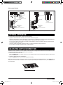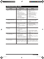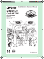
1
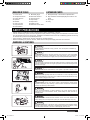
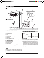
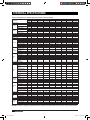
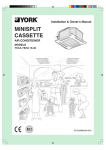
Installation & Ownerʼs Manual
MINISPLIT
CASSETTE
AIR CONDITIONER
MODELS
YKCC-YKHC 12-48
YKKC 07-18
EN 035M00054-001
J391_EN.indd 1
3/14/07 1:31:42 PM
CONTENTS
Safety Precautions .................................................. 3
Part Names ............................................................... 4
Technical Specifications ......................................... 5
Dimensions ............................................................ 10
Installations............................................................ 12
Condensate Drainage ........................................... 19
Refrigerant Piping Connections........................... 20
Wiring Diagrams .................................................... 21
Optimal Operation ................................................. 23
Adjustiong Air Flow Direction .............................. 23
Emergency Operations ......................................... 24
Maintenance ........................................................... 24
Please read this installation
manual carefully before starting
the installation. It will tell you
necessary information.
Operation Tips ....................................................... 26
Troubleshooting Guide ......................................... 27
Declaration of Conformity .................................... 28
Refrigerant
Model
Set
Outdoor
Indoor
Outdoor
Indoor
DC INVERTER R-410A
18-24
36-48
YKHCxxDSBAAR
YKHCxxDSBACR
YKJCxxDS-BAR
YKJCxxDS-BCR
YKKCxxDS-BAR
YKKCxxDS-BCR
Multi Inverter R-410A
50Hz/1Ph
RRJCxxAA-AAA
YKKCxxAA-AAR
Standard
Refrigerant
Model
Set
Outdoor
Indoor
R-410A
12-24
30-48
YKHCxxFSAAAR
YKHCxxFSAACR
YKJCxxFS-AAR
YKJCxxFS-ACR
YKKCxxFS-AAR
YKKCxxFS-ACR
With Low Ambient Kit
Quality POLICY
We will continuously strive to satisfy
our customers with consistent reliability in product, service and support
through superior quality, service
culture and distinctive technology.
J391_EN.indd 2
Refrigerant
Model
Set
Outdoor
Indoor
R-410A
12-24
30-48
YKHCxxFSBAAR
YKHCxxFSBACR
YKJCxxFS-AAR
YKJCxxFS-ACR
YKKCxxFS-AAR
YKKCxxFS-ACR
Refrigerant
Model
Set
Outdoor
Indoor
R-410A
12-30
30-48
YKCC/YKHCxxFSAAAA YKCC/YKHCxxFSAAC
YKDC/YKJCxxFS-AAR
YKDC/YKJCxxFS-ACR
YKEC/YKKCxxFS-AAR YKEC/YKKCxxFS-ACR
3/14/07 1:31:45 PM
REQUIRED TOOLS
1.
2.
3.
4.
5.
6.
7.
8.
Screw driver
Hexagonal wrench
Torque wrench
Spanner
Reamer
Hole core drill
Tape measure
Thermometer
EXTENDED PARTS
9.
10.
11.
12.
13.
14.
15.
Manifold gauge
Gas leak detector
Vacuum pump
Pipe clamp
Pipe cutter
Flare tool set
Electrical circuit tester
1. Refrigerant Pipe : See Technical Specification
2. Pipe insulation material (Polyethylene foam 9 mm
thick)
3. Vinyl tape
4. Putty
SAFETY PRECAUTIONS
• Please read this installation manual carefully before starting installation of the unit.
• This air conditioning system contains refrigerant under pressure, rotating parts and electrical connection which
may be dangerous and can cause injury. Installation and maintenance of this air conditioning system should only
be carried out by trained and qualified personnel.
• After unpacking, please check the unit carefully for possible damage.
• Before undertaking any work on the unit, make sure that the power supply has been disconnected.
WARNING & CAUTIONS
Danger
CAUTION
Do not attempt to install this unit by yourself. This unit requires installation by
qualified persons.
DANGER
Do not attempt to service the unit yourself. This unit has no user serviceable
components. Opening or removing the cover will expose you to dangerous
voltage. Turning off the power supply will not prevent potential electric shock.
DANGER
Never put hands or objects into the Air Outlet of indoor or outdoor units. These
units are installed with a fan running at high speed. To touch the moving fan will
cause serious injury.
No
DANGER
To avoid the risk of serious electrical shock, never sprinkle or spill water or liquids on unit.
WARNING
Ventilate the room regularly while the air conditioner is in use, especially if there
is also a gas appliance in use in this room. Failure to follow these directions may
result in a loss of oxygen in the room.
WARNING
To prevent electric shock, turn off the power or disconnect the power supply
plug before beginning any cleaning or other routine maintenance. Follow the
directions for cleaning in this manual.
WARNING
Do not use liquid cleaners or aerosol cleaners, use a soft and dry cloth for
cleaning the unit. To avoid electric shock, never attempt to clean the unit by
sprinkling water.
WARNING
Thinner
Do not use caustic household drain cleaners in the unit. Drain cleaners can
quickly destroy the unit components (drain pan and heat exchanger coil, etc.)
WARNING
For proper performance, operate the unit in temperature and humidity ranges
indicated in this manual. If the unit is operated beyond these conditions, it may
cause abnormal functions of the unit or dew dripping from the unit.
ENGLISH
J391_EN.indd 3
3
3/14/07 1:31:49 PM
PART NAMES
INDOOR UNIT
I
J
K
H
A
L
G
M
E
D
F
N
E
P
O
Display Panel
B
OUTDOOR UNIT
C
■ INDOOR & OUTDOOR UNIT
A. Indoor unit
B. Outdoor unit
C. Remote controller
D. Air-in
E. Air-out
F. Air flow louver (at air outlet)
G. Connecting pipe
H. Drain hose
I. Return Grill (with air filter)
J. Drain pump (drain water from indoor unit)
■ DISPLAY PANEL
K. Infrared signal receiver
L. Emergency button
M. Running indicator
N. Timer indicator
O. Frost indicator (cooling and heating type)
or fan indicator (cooling only type)
P. Pump indicator
D
E
OPERATING TEMPERATURE
Mode
Temperature
Cooling
operation
Heating
operation
Drying
operation
Room temperature
17°C~32°C
0°C~30°C
17°C~30°C
Outdoor
temperature
21°C~43°C
-7°C~24°C
11°C~43°C
CAUTIONS
1. If air conditioner is used outside of the above conditions,
certain safety protection features may come into
operation which cause the unit to function abnormally.
2. Room relative humidity is less than 80%. If the air
conditioner operates in excess of this figure, the surface
of the air conditioner may attract condensation.
Please set the vertical air flow louver to its maximum
angle (Vertically to the floor), and set HIGH fan mode.
3. Optimum performance will be achieved within these
operating temperature.
NOTE
All the pictures in this manual are for explanation
purpose only. They may be sightly different from the
air conditioner you purchased. The actual shape shall
prevail.
4
J391_EN.indd 4
ENGLISH
3/14/07 1:31:53 PM
TECHNICAL SPECIFICATIONS
TECHNICAL SPECIFICATION: Ceiling Cassette YKHC “R-410A” -50Hz
Indoor
Unit
Models
Outdoor
Unit
YKKC
12
24
30
36
48
36
48
YKJC
12
V/Ph/Hz
Power Supply
18
18
24
30
220-240/1/50
380/3/50
Ph
1
1
1
3
3
3
Power Consumption
W
1160/1156
1900/1900
2560/2500
3250/3250
3700/3350
4700/4900
Running Current
A
6.0/6.8
8.8/8.8
12.2/11
5.5/5.5
6.5/5.8
8.2/8.6
R-410A
Refrigerant Type
Refrigerant Charge
Noise level
gr
Indoor
Outdoor
Fan
2050
2600
3100
3100
4000
36
43
43
47
47
47
43
48
55
57
57
58
V/Ph/Hz
Power Supply
Indoor Unit
dB(A)
1120
Air flow
220-240/1/50
Ph
1
1
1
1
1
1
m3/h
780
860
1050
1600
1600
1600
Input Power
W
63
63
120
137
137
137
Running Current
A
0.29
0.29
0.58
0.66
0.66
0.66
Height
mm
254
254
240
310
310
310
Width
mm
580
580
840
840
840
840
Depth
mm
580
580
840
840
840
840
kg
21
21
36
40
40
40
Dimension
Weight
System Operation Control
V/Ph/Hz
Power Supply
Dimension
Ph
Qty
220-240/1/50Hz
380/3/50Hz
1
1
1
3
3
3
1
1
1
1
1
1
Compressor Type
Rotary
Scroll
Height
mm
590
695
860
960
960
1245
Width
mm
760
845
895
990
990
940
Depth
mm
285
335
330
360
360
360
kg
41.5
55
79
101
101
110
Weight
Piping
Outdoor Unit
Compressor
Wireless Control with LCD Display
Type
Pipe Size
Flare + Nuts
Suction
inch
1/2
1/2
5/8
3/4
3/4
3/4
Liquid
inch
1/4
1/4
3/8
1/2
1/2
1/2
Remark: The above design and specifications are subject to change without prior notice for product improvement.
ENGLISH
J391_EN.indd 5
5
3/14/07 1:31:57 PM
TECHNICAL SPECIFICATIONS
Technical Specifications Cassette Type YKCC/YKHC12-48 R410A-50Hz
York Model
Power supply
Capacity
Cooling
Input
Rated current
Capacity
Heating
Input
Rated current
Moisture Removal
Max. input consumption
Max. current
Starting current
Type
Input
Rated current (RLA)
Compressor
Locked rotor Amp (LRA)
Thermal protector
Capacitor
Refrigerant oil
Input
Running current
Indoor
(Hi/Med/Lo)
fan motor
Capacitor
Speed (Hi/Med/Lo)
Number of rows
Fin spacing
Fin type
Indoor
Tube outside dia.
coil
Material Type
Coil length x height
x width
Indoor air flow (Hi/Med/Lo)
Indoor noise level (Hi/Med/Lo)
Dimension (W*H*D)
(body)
Packing (W*H*D)
(body)
Net/Gross weight
(body)
Indoor
unit
Dimension (W*H*D)
(panel)
Packing (W*H*D)
(panel)
Net/Gross weight
(panel)
Input
Running current
Outdoor
fan motor
Capacitor
Speed
Number of rows
Fin spacing
Outdoor
coil
Set
Indoor
Outdoor
Ph-V-Hz
Btu/h
kW
W
A
Btu/h
kW
W
A
L/h
W
A
A
W
A
A
µF
ml
W
YKHC12FSAAAR
YKKC12FS-AAR
YKJC12FS-AAR
1,220-240V,50Hz
12000
3.5
1165
5.3
13000
3.8
1200
6.8
1.2
1950
8.9
26
ROTARY
1145
5.3
26
INNER
35
480
63/57/47
YKCC18FSAAAR
YKEC18FS-AAR
YKDC18FS-AAR
1,220-240V,50Hz
18000
5.4
1900
8.5
/
/
/
/
1.8
2600
13
36.8
ROTARY
1870
8.75
36.8
INNER
50
750
64/57/48
YKHC18FSAAAR
YKKC18FS-AAR
YKJC18FS-AAR
1,220-240V,50Hz
18000
5.4
1900
8.8
20500
6
1900
8.8
1.8
2300
11.7
36.8
ROTARY
1870
8.75
36.8
INNER
50
750
63/57/47
YKCC24FSAAAR
YKEC24FS-AAR
YKDC24FS-AAR
1,220-240V,50Hz
24000
7.1
2600
12.1
/
/
/
/
2.4
3300
16.5
61
ROTARY
2430
11.4
61
INNER
50
950
128/105/43
YKHC24FSAAAR
YKKC24FS-AAR
YKJC24FS-AAR
1,220-240V,50Hz
24000
7.1
2510
12.2
27300
8
2500
11
2.4
3300
15.3
61
ROTARY
2430
11.4
61
INNER
50
950
128/105/43
YKCC30FSAAAR
YKEC30FS-AAR
YKDC30FS-AAR
1,220-240V,50Hz
30000
9.2
3450
16.1
/
/
/
/
3
5200
25
97
SCROLL
3750
18.1
97
INNER
60
1700
140/100/45
YKHC30FSAAAR
YKKC30FS-AAR
YKJC30FS-AAR
1,220-240V,50Hz
30000
9.2
3270
17
32000
9.4
3232
14.7
3
4620
21
97
SCROLL
3650
17.65
97
INNER
60
1700
140/100/45
A
0.29/0.27/0.24
0.29/0.27/0.24
0.29/0.27/0.24
0.29/0.27/0.24
0.58/0.48/0.2
0.58/0.48/0.2
0.65/0.5/0.22
0.65/0.5/0.22
µF
r/min
2.5µF/450V
930/830/660
2
1.3
2.5µF/450V
930/830/660
2
1.3
2.5µF/450V
930/830/660
2
1.3
2.5µF/450V
3.5µF/450V
930/830/660
680/600/330
2
2
1.3
1.3
Hydrophilic aluminum
Ø7
Innergroove tube
3.5µF/450V
680/600/330
2
1.3
3.5µF/450V
670/570/340
2
1.3
3.5µF/450V
670/570/340
2
1.3
mm
mm
mm
1185×210×26.74
1185×210×26.74
1185×210×26.74
1185×210×26.74
1950×126×26.74
1950×126×26.74
1950×168×26.74
1950×168×26.74
m3/h
dB(A)
680/600/400
41/38/35
680/600/400
41/38/35
860/760/500
44/41/38
860/760/500
44/41/38
1050/900/500
46/44/42
1050/900/500
46/44/42
1600/1420/1200
48/46/44
1600/1420/1200
48/46/44
mm
580×254×580
580×254×580
580×254×580
580×254×580
840×240×840
840×240×840
840×310×840
840×310×840
mm
750×340×750
750×340×750
750×340×750
750×340×750
1010x340x930
1010x340x930
1010x410x930
1010x410x930
kg
21/30
21/30
21/30
21/30
36/43
36/43
40/47
40/47
mm
650×30×650
650×30×650
650×30×650
650×30×650
950×40×950
950×40×950
950×40×950
950×40×950
mm
715×115×715
715×115×715
715×115×715
715×115×715
1030×145×1030
1030×145×1030
1030×145×1030
1030×145×1030
kg
3/5
3/5
3/5
3/5
6/11
6/11
6/11
6/11
W
A
µF
r/min
56
0.27
2.5
800
2
1.4
Hydrophilic
aluminium
136
0.61
3
800
2
1.7
Unhydrophilic
aluminum
130
0.592
2.5
750
2
1.8
Hydrophilic
aluminium
138
0.66
3
800
2
1.5
Hydrophilic
aluminium
296
1.38
10
740
2
1.7
Unhydrophilic
aluminum
296
1.38
10
740
2
1.7
Unhydrophilic
aluminium
mm
56
0.27
2.5
800
2
1.5
Unhydrophilic
aluminum
Ø7
mm
651x559x44
651x559x44
775×660×44
775×660×44
850×810×44
850×810×44
955×915×44
955×915×44
m3/h
dB(A)
mm
mm
kg
g
mm
mm
m
m
2100
43
760×590×285
887x655x355
44/48
1100
6.35
12.7
25
15
2100
43
760×590×285
910x575x335
44/48
1120
6.35
12.7
25
15
2400
48
845×695×335
970x770x395
57/62
2000
6.35
12.7
25
15
2400
48
845×695×335
970x770x395
57/62
2050
6.35
12.7
25
15
3000
55
895×860×330
1043x915x395
68/70
2600
9.53
16
30
15
3000
55
895×860×330
1043x915x395
69/74
2600
9.53
16
30
15
5000
57
990×960×360
1120x1090x435
90/102
3000
12.7
19
30
20
5000
57
990×960×360
1120x1090x435
90/102
3450
12.7
19
30
20
mm
Fin type
Tube outside dia.
Material Type
Coil length x height
x width
Outdoor air flow
Outdoor noise level
Dimension (W*H*D)
Outdoor
Packing (W*H*D)
unit
Net/ Gross weight
Refrigerant R-410A Quantity
Liquid side
Gas side
Refrigerant
piping
Max. pipe length
Max. difference in level
YKCC12FSAAAR
YKEC12FS-AAR
YKDC12FS-AAR
1,220-240V, 50Hz
12000
3.5
1200
6
/
/
/
/
1.2
1400
7.2
26
ROTARY
1145
5.3
26
INNER
35
480
64/57/48
138
0.66
3
800
2
1.5
Unhydrophilic
aluminum
Ø9.53
Innergroove tube
Remark: The above design and specifications are subject to change without prior notice for product improvement.
6
J391_EN.indd 6
ENGLISH
3/14/07 1:32:00 PM
TECHNICAL SPECIFICATIONS
Technical Specifications Cassette Type YKCC/YKHC12-48 R410A-50Hz
York Model
Power supply
Capacity
Cooling
Input
Rated current
Capacity
Heating
Input
Rated current
Moisture Removal
Max. input consumption
Max. current
Starting current
Type
Input
Rated current (RLA)
Compressor
Locked rotor Amp (LRA)
Thermal protector
Capacitor
Refrigerant oil
Input
Running current
Indoor
(Hi/Med/Lo)
fan motor
Capacitor
Speed (Hi/Med/Lo)
Number of rows
Fin spacing
Fin type
Indoor
Tube outside dia.
coil
Material Type
Coil length x height
x width
Indoor air flow (Hi/Med/Lo)
Indoor noise level (Hi/Med/Lo)
Dimension (W*H*D)
(body)
Packing (W*H*D)
(body)
Net/Gross weight
(body)
Indoor
unit
Dimension (W*H*D)
(panel)
Packing (W*H*D)
(panel)
Net/Gross weight
(panel)
Input
Running current
Outdoor
fan motor
Capacitor
Speed
Number of rows
Fin spacing
Outdoor
coil
Set
Indoor
Outdoor
Ph-V-Hz
Btu/h
kW
W
A
Btu/h
kW
W
A
L/h
W
A
A
µF
ml
W
YKCC30FSAACR
YKEC30FS-ACR
YKDC30FS-ACR
3,380V,50Hz
30000
9.2
3450
6.4
/
/
/
/
3
5200
8.8
61
SCROLL
3650
6.58
61
INNER
/
1700
140/100/45
YKHC30FSAACR
YKKC30FS-ACR
YKJC30FS-ACR
3,380V,50Hz
30000
9.2
3250
5.5
32000
9.5
3250
5.5
3
4620
8.5
61
SCROLL
3650
6.58
61
INNER
/
1700
140/100/45
YKCC36FSAAAR
YKEC30FS-AAR
YKDC30FS-AAR
1,220-240V,50H
36,000
10.5
3800
19.2
/
/
/
/
3.6
5200
26.3
97
SCROLL
3750
18.1
97
INNER
60
1700
140/100/45
YKHC36FSAAAR
YKKC30FS-AAR
YKJC30FS-AAR
1,220-240V,50Hz
36,000
10.5
3750
17
38000
11.1
3720
16.8
3.6
4620
21
97
SCROLL
3650
17.65
97
INNER
60
1700
140/100/45
YKCC36FSAACR
YKEC36FS-ACR
YKDC36FS-ACR
3,380V,50Hz
36000
10.5
3800
6.4
/
/
/
/
3.8
5200
8.8
61
SCROLL
3650
6.58
61
INNER
/
1700
140/100/45
YKHC36FSAACR
YKkC36FS-ACR
YKJC36FS-ACR
3,380V,50Hz
36000
10.5
3700
6.5
39000
11.4
3350
5.8
3.8
4620
8.5
61
SCROLL
3650
6.58
61
INNER
/
1700
140/100/45
YKCC48FSAACR
YKEC48FS-ACR
YKDC48FS-ACR
3,380V,50Hz
48000
14
4900
8.2
/
/
/
/
4.8
6100
10.3
66
SCROLL
4750
8.22
66
INNER
/
1700
140/100/45
YKHC48FSAACR
YKKC48FS-ACR
YKJC48FS-ACR
3,380V,50Hz
48000
14
4700
8.2
52000
15.2
4900
8.6
4.8
5870
10.7
66
SCROLL
4750
8.22
66
INNER
/
1700
140/100/45
A
0.65/0.5/0.22
0.65/0.5/0.22
0.65/0.5/0.22
0.65/0.5/0.22
0.65/0.5/0.22
0.65/0.5/0.22
0.65/0.5/0.22
0.65/0.5/0.22
µF
r/min
3.5µF/450V
670/570/340
2
1.3
3.5µF/450V
670/570/340
2
1.3
3.5µF/450V
670/570/340
2
1.3
3.5µF/450V
3.5µF/450V
670/570/340
670/570/340
2
2
1.3
1.3
Hydrophilic aluminum
Ø7
Innergroove tube
3.5µF/450V
670/570/340
2
1.3
3.5µF/450V
670/570/340
2
1.3
3.5µF/450V
670/570/340
2
1.3
W
A
A
mm
mm
mm
1950×168×26.74
1950×168×26.74
1950×168×26.74
1950×168×26.74
1950×168×26.74
1950×168×26.74
1950×168×26.74
1950×168×26.74
m3/h
dB(A)
1600/1420/1200
48/46/44
1600/1420/1200
48/46/44
1600/1420/1200
48/46/44
1600/1420/1200
48/46/44
1600/1420/1200
48/46/44
1600/1420/1200
48/46/44
1600/1420/1200
48/46/44
1600/1420/1200
48/46/44
mm
840×310×840
840×310×840
840×310×840
840×310×840
840×310×840
840×310×840
840×310×840
840×310×840
mm
1010x410x930
1010x410x930
1010x410x930
1010x410x930
1010x410x930
1010x410x930
1010x410x930
1010x410x930
kg
40/47
40/47
40/47
40/47
40/47
40/47
40/47
40/47
mm
950×40×950
950×40×950
950×40×950
950×40×950
950×40×950
950×40×950
950×40×950
950×40×950
mm
1030×145×1030
1030×145×1030
1030×145×1030
1030×145×1030
1030×145×1030
1030×145×1030
1030×145×1030
1030×145×1030
kg
6/11
6/11
6/11
6/11
6/11
6/11
6/11
6/11
W
A
µF
r/min
296
1.38
10
740
2
1.7
Unhydrophilic
aluminium
296
1.38
10
740
2
1.7
Unhydrophilic
aluminum
296
1.38
10
740
2
1.7
Unhydrophilic
aluminium
296
1.38
10
740
2
1.7
Unhydrophilic
aluminium
148X2
0.7X2
3.5
800
2
1.8
Unhydrophilic
aluminum
148X2
0.7X2
3.5
800
2
1.8
Hydrophilic
aluminium
mm
296
1.38
10
740
2
1.7
Unhydrophilic
aluminum
Ø7
mm
955×915×44
955×915×44
955×915×44
955×915×44
955×915×44
955×915×44
715×1220×44
715×1220×44
m3/h
dB(A)
mm
mm
kg
g
mm
mm
m
m
5000
57
990×960×360
1120x1090x435
90/102
3000
12.7
19
30
20
5000
57
990×960×360
1120x1090x435
90/102
3100
12.7
19
30
20
5000
57
990×960×360
1120x1090x435
90/102
3000
12.7
19
30
20
5000
57
990×960×360
1120x1090x435
90/102
3450
12.7
19
30
20
5000
57
990×960×360
1120x1090x435
90/102
3000
12.7
19
30
20
5000
57
990×960×360
1120x1090x435
90/102
3100
12.7
19
30
20
6000
58
940×1245×340
1058x1380x435
112/127
3700
12.7
19
50
30
6000
58
940×1245×340
1058x1380x435
112/127
4000
12.7
19
50
30
mm
Fin type
Tube outside dia.
Material Type
Coil length x height
x width
Outdoor air flow
Outdoor noise level
Dimension (W*H*D)
Outdoor
Packing (W*H*D)
unit
Net/ Gross weight
Refrigerant R-410A Quantity
Liquid side
Gas side
Refrigerant
piping
Max. pipe length
Max. difference in level
296
1.38
10
740
2
1.7
Unhydrophilic
aluminum
Ø9.53
Innergroove tube
Remark: The above design and specifications are subject to change without prior notice for product improvement.
ENGLISH
J391_EN.indd 7
7
3/14/07 1:32:05 PM
TECHNICAL SPECIFICATIONS
TECHNICAL SPECIFICATION: EVEREST MULTI INVERTER “YKKC-RRJC” 50 Hz
Indoor Unit Cassette Type YKKC07-18
Model
YKKC07AA-AAR
YKKC09AA-AAR
YKKC12AA-AAR
Power supply
Ph-V-Hz
1Ph, 220-240V~,50Hz 1Ph, 220-240V~,50Hz 1Ph, 220-240V~,50Hz
Cooling Capacity
BTU/h
7,000
9,000
12,000
Capacity
Heating Capacity
BTU/h
8,500
11,000
14,000
Power Input
W
63
63
63
Indoor fan
Capacitor
µF
1.5µF/450V
1.5µF/450V
1.5µF/450V
motor
Speed (Hi/Mi/Lo)
r/min
750/660/540
750/660/540
830/730/680
Number of rows
2
2
2
Fin spacing
mm
1.3
1.3
1.3
Fin type
Hydrophilic aluminium
Indoor coil
Tube outside dia.
mm
Ø7.94
Tube Material
Innergroove tube
Coil length x height x width
mm
1185x210x26.7
1185x210x26.7
1185x210x26.7
Indoor air flow (Hi/Mi/Lo)
m3/h
600/500/420
600/500/420
680/580/500
Indoor noise level (Hi/Mi/Lo)
dB(A)
36/33/30
36/33/30
36/33/30
Pipe size
Liquid side/Gas side
mm
Ø6.35/Ø9.53
Ø6.35/Ø9.53
Ø6.35/Ø12.7
Dimension (W*H*D)
mm
580×254×580
580×254×580
580×254×580
Indoor unit
Packing (W*H*D)
mm
750x340×750
750x340×750
750x340×750
(body)
Net/Gross weight (body)
kg
21/28
21/28
21/28
Dimension (W*H*D)
mm
650x30x650
650x30x650
650x30x650
Indoor unit
Packing (W*H*D)
mm
715x115x715
715x115x715
715x115x715
(panel)
Net/Gross weight (panel)
kg
3/5
3/5
3/5
YKKC18AA-AAR
1Ph, 220-240V~,50Hz
18,000
21,000
63
2.5µF/450V
930/830/660
2
1.3
1185x210x26.7
860/760/650
43/40/38
Ø6.35/Ø12.7
580×254×580
750x340×750
28/36
650x30x650
715x115x715
3/5
Outdoor Unit Multi Inverter RRJC18-27
Model
Indoor Units Combination
Power supply
Cooling
Heating
Max. input
Max. current
Compressor
Outdoor fan
motor
Outdoor coil
Capacity
Input
Rated current
Capacity
Input
Rated current
Type
Input
Rated current (RLA)
Locked rotor Amp (LRA)
Thermal protector
Capacitor
Refrigerant oil
Input
Capacitor
Speed
Number of rows
Fin spacing
Fin type
Tube outside dia.
Tube Material
Coil length x height x width
Number of circuits
Outdoor air flow
Outdoor noise level
Dimension (W*H*D)
Outdoor unit
Packing (W*H*D)
Net/Gross weight
Refrigerant Type R-410A
Liquid side/Gas side
Transfer Connector (9.53→12.7)
Refrigerant
piping
Max. refrigerant pipe length
Max. difference in level
Ph-V-Hz
Btu/h
W
W
A
Btu/h
W
W
A
W
A
W
A
A
µF
ml
W
µF
r/min
mm
mm
mm
m3/h
dB(A)
mm
mm
kg
g
mm
mm
m
m
RRJC18AA-AAA
Single
Double
1Ph, 220-240V~,50Hz
7000~12000
18000
2050~3517
5275
1000~1300
1813
4.8~6.5
11.5
9000~14000
21000
2638~4103
6155
1300~1600
2038
6.3~7.8
11.0
3200
20
Rotary inverter
1690
11.6
60
Internal
85µF/250V
750
148
3
775
2
1.7
Hydrophilic aluminium
Ø9.53
Innergroove tube
776×660×22
2
2500
60
845x695x335
965x772x405
71/74
2100
Ø6.35/Ø9.53
2
15 (each indoor unit)
10 (each indoor unit)
RRJC27AA-AAA
Double
1Ph, 220-240V~,50Hz
7000~12000
16000~24000
2000~3500
4690~7000
1000~1300
2570~2850
4.8~6.5
11.7~13.5
10000~14000
24000~27000
2900~4100
7000~7900
1300~1600
2100~2750
6.3~7.8
11.0~13.2
3200
20
Rotary inverter
1690
11.6
60
Internal
85µF/250V
750
148
3
775
2
1.7
Hydrophilic aluminium
Ø9.53
Innergroove tube
776×660×22
2
2500
60
845x695x335
965x772x405
72/76
2250
3 x Ø6.35/Ø9.53
2
15 (each indoor unit)
10 (each indoor unit)
Single
Treble
27000
7913
2806
13.5
30000
8792
2739
13.2
Remark: The above design and specifications are subject to change without prior notice for product improvement.
8
J391_EN.indd 8
ENGLISH
3/14/07 1:32:08 PM
TECHNICAL SPECIFICATIONS
TECHNICAL SPECIFICATION: CASSETTE DC INVERTER “YOHC” R-410A, 50Hz
Set
YKHC18DSBAAR
YKHC24DSBAAR
YKHC36DSBACR
YKHC48DSBACR
Indoor
YKKC18DS-BAR
YKKC24DS-BAR
YKKC36DS-BCR
YKKC48DS-BCR
Outdoor
YKJC18DS-BAR
YKJC24DS-BAR
YKJC36DS-BCR
YKJC48DS-BCR
V-Ph-Hz
220~240-1-50
220~240-1-50
380V~3~ 50Hz
380V~3~ 50Hz
Btu/h
18000
24000
36000
48000
Input
W
1620
2180
3280
4330
Rated current
A
6.7
9.1
8.72
11.4
Btu/h
21000
28000
40000
53000
Input
W
1700
2230
3180
4200
Rated current
A
7.2
9.35
8.41
10.96
Max. input consumption
W
2400
2730
3780
4890
Max. current
A
9.8
11.1
10.2
12.95
A
1.08
1.15
1.1
Model
Power supply
Capacity
Cooling
Capacity
Heating
Starting current
Type
Compressor
DC Inverter Rotary
Input
W
1650
1650
3665
3665
Rated current (RLA)
A
8
8
7.8
7.8
Locked rotor Amp (LRA)
A
28
28
28
28
Protector
Thermal
Capacitor
µF
50
50
50
50
Refrigerant oil
ml
480
480
500
500
Input
W
75
95
3.5
3.5
Capacitor
µF
4
4
-
-
r/min
550/490/440
630/550/470
630/580/530
630/580/530
2
2
1
1
mm
1.3
1.3
1.3
1.3
Type
Indoor fan motor
Speed (Hi/Me/Lo)
AC Motor
Number of rows
Fin spacing
Indoor coil
Fin type
Tube outside dia.
Hydrophilic aluminium
mm
Ø7
Tube Material
Coil length x height x width
mm
2000x170x27
1950×126×26.74
1950×168×13.37
1950×168×13.37
800/700/600
920/770/675
1600/1420/1200
1600/1420/1200
dB(A)
49/-/-
52/-/-
48/46/44
48/46/44
Dimension (W*H*D)
mm
840x840x310
840x840x310
840×310×840
840×310×840
Packing (W*H*D)
mm
1010x930x340
1010x930x340
1010x930x340
1010x410x930
Net/Gross weight
kg
32/35
32/35
32/35
40/47
Input
W
129
150
10
3.5*2
Capacitor
µF
3
3
-
-
r/min
770
800
740
800
2
2
1
1
mm
1.7
1.5
25.4/22
25.4/22
Indoor noise level (Hi/Me/Lo)
Outdoor fan
motor
Innergroove tube
m3/h
Indoor air flow (Hi/Me/Lo)
Indoor unit
Speed
Number of rows
Fin spacing
Outdoor coil
Fin type
Tube outside dia.
Hydrophilic aluminium
mm
Ø9.52
Tube Material
Coil length x height x width
Innergroove tube
mm
630X660X44
620X813X44
955×915×22
715×610×22
m3/h
2400
3000
5000
6000
dB(A)
56
55
57
58
Dimension (W*H*D)
mm
840x677x310
894x860x302
990×960×340
940x1245x340
Packing (W*H*D)
mm
965x770x395
1043x915x395
1120x1015x435
1058x1300x435
Net/Gross weight
kg
62.5/66.5
72/76.5
106/111
117/126
g
1650
2200
2600
3550
EXV&Capillary
EXV&Capillary
EXV&Capillary
EXV&Capillary
6.35/12.7
9.53/16
9.53/16
9.53/16
Outdoor air flow
Outdoor noise level
Outdoor unit
Refrigerant R-410A
Throttle type
Refrigerant
piping
1.16
DC Inverter Scroll
Liquid side/ Gas side
mm
Remark: The above design and specifications are subject to change without prior notice for product improvement.
ENGLISH
J391_EN.indd 9
9
3/14/07 1:32:10 PM
DIMENSIONS
INDOOR UNIT
Drain side and
Tubing side
■ YKKC 07-18
254
Nut
422
650 (Panel)
580 (Body)
600 (Ceiling hole)
611 (Hook-location)
Hook
Body
Ceiling
67
28.5
401 (Hook-location)
580 (Body)
Panel
600
Control box needs access
through ceiling
600 (Ceiling hole)
650 (Panel)
■ YKKC 24-48
240
135
130
115
690
130
120
27
97
151
156
Gas side
140
Liquid side
27
97
151
156
4-Install hanger
840
785
778
Control box
Drain outlet
679
840
139
139
Pump inspection
hole
130
200
130
190
310
YKKC 24-48
YKKC 24
YKKC 30-48
■ DC Inverter R-410A
Connecting point of drain pipe
Drain side
J391_EN.indd 10
A
H
Ceiling
>2500mm
840 (Body)
(Gas side ØB)
Outlet
Inlet
Outlet
880mm (ceiling hole)
Panel
Table 1
mm
MODEL
A
B
C
H
18000
240
Ø12.7
Ø6.35
>260
840 (Body)
24000
240
Ø16
Ø9.53
>260
950 (Panel)
36000
310
Ø16
Ø9.53
>330
48000
310
Ø16
Ø9.53
>330
Ground
780 (Hook-location)
10
Connecting point of refrigerant pipe
(Liquid side ØC)
Connecting point of refrigerant pipe
950 (Panel)
680 (Hook-location)
Tubing side
(Unit: mm)
ENGLISH
3/14/07 1:32:16 PM
OUTDOOR UNIT
■ YKDC-YKJC 12-18
■ YKDC-YKJC 24
313
845
895
300
135
351.2
860
695
301.5
560.1
590
163
335
330
125
235
141.5
■ YKDC-YKJC 30-36
336.4
400
940
1245
960
990
■ YKDC-YKJC 48
624
360
360
181.4
650
■ RRJC 18-27
■ DC Inverter R-410A
H
688
790
A
300
310
520
D
C
E
B
Table 2
mm
MODEL
A
B
C
D
E
H
18
840
560
335
360
310
677
24
894
590
333
355
302
860
36
990
624
366
396
340
960
48
940
600
376
400
340
1245
REMARK
R-410A
ENGLISH
J391_EN.indd 11
11
3/14/07 1:32:24 PM
INSTALLATIONS
CAUTIONS
Location in the following places may cause malfunction of the machine. (If unavoidable, please consult your local dealer)
a. There is petrolatum existing.
b. There is salty air surrounding (near the coast).
c. There is caustic gas (the sulfide, for example) existing in the air (near a hot spring).
d. The Volt varies violently (in the factories).
e. In buses or cabinets.
f. In kitchen where oil or gas are present.
g. There is strong electromagnetic wave existing.
h. There are inflammable materials or gas.
i. There is acid or alkaline liquid evaporating.
j. Other special conditions.
NOTICES BEFORE INSTALLATION
1. Select the correct carry-in path.
2. Move this unit as originally packaged as possible.
3. The air conditioner must be electrically insulated according to the relevant standards to electrical appliances.
1. The indoor unit
• There is enough room for installation and maintenance.
• The ceiling is horizontal, and its structure can endure the weight of the indoor unit.
• The air outlet and the air inlet are not impeded, and the influence of external air is the least.
• The air flow can reach throughout the room.
• The connecting pipe and drainpipe could be extracted out easily.
• There is no direct radiation from heaters.
2. The outdoor unit
• There is enough room for installation and maintenance.
• The air outlet and the air inlet are not impeded, and cannot be reached by strong wind.
• It must be a dry and well ventilating place.
• The base is flat, level and can support the weight of the outdoor unit without vibration.
• Your neighborhood will not feel uncomfortable with the noise or expelled air.
• There is no leakage of combustible air.
• It is easy to install the connecting pipe or cables.
• Determine the air outlet direction where the discharged air is not blocked.
• A place is free from a leakage of combustible gases.
In the case that the installation place is exposed to a strong wind such as a seaside or high position, secure the
normal fan operation by putting the unit lengthwise along the wall or using a duct or shield plates.
• If possible, do not install the unit which is exposed to direct sunlight.
• If necessary, install a blind that does not interfere with the air flow.
• During the heating mode, the water drained off the outdoor unit. The condensate should be well drained away
by the drain hole to an appropriate place so as not to interfere other people or public.
• Select the position that will not be subject to snow drifts, accumulation of leaves or other seasonal debris. It is
important that the air flow for the outdoor unit is not impeded as this will result in reduction in heating or cooling
performance.
INDOOR UNIT INSTALLATION
1. INSTALL THE MAIN BODY
A. The existing ceiling (to be horizontal)
a. Cut a square hole of 880 x 880 mm. in the ceiling according to the shape of the installation paper board.
(Refer to chart 3, 4)
• The center of the hole should be at the same position of that of the air conditioner body.
• Determine the lengths and outlets of the connecting pipe, drainpipe, and cables.
• Strengthen the ceiling as necessary to avoid vibration.
12
J391_EN.indd 12
ENGLISH
3/14/07 1:32:44 PM
b. Select the position of installation hooks according to the hook holes on the installation board.
• Drill four holes of 12 mm., 45 ~ 50 mm. deep at the selected positions on the ceiling. Then embed the expandable
hooks (fittings).
• Face the concave side of the installation hooks toward the expandable hooks. Determine the length of the
installation hooks from the height of ceiling, then cut off the unnecessary part.
• If the ceiling is extremely high, determine the length of the installation hook according to facts.
• For size 12-18 provide access for control box.
Necessary room
A
ground
Chart 1
Note: 12000-24000 Btu/h Series A ≥ 260 mm.
30000-48000 Btu/h Series A ≥ 330 mm.
950 (Panel)
outlet
840 (Body)
880 (Ceiling hole)
inlet
Tubing side
780 (Hook-location)
>2500 mm.
outlet
A
Drain side
Hook
Body
780 (Hook-location)
B
Nut
840 (Body)
880 (Ceiling hole)
Ceiling
950 (Panel)
880 mm.
>1000 mm.
Chart 2
Note: 12000-24000 Btu/h Series B ≥ 240 mm.
30000-48000 Btu/h Series B ≥ 310 mm.
>1000 mm.
>1000 mm.
Panel
Chart 4
Body
>1000 mm.
(Unit : mm.)
Central hole
Installation paper board
Bolt
M6 x 12
Chart 3
Chart 5
Note: The dimension of 24000 Btu/h and 30000 Btu/h (3 PHASE) are the same.
The dimension of 30000 Btu/h and 36000 Btu/h (1 PHASE) are the same.
H (Ceiling height)
34 mm.
The length could be calculated from Chart 5.
Length=H-181+L (in general, L=100 mm. and is half of the whole length of the installation hook)
c. Adjust the nuts on the four installation hooks evenly to ensure the balance of the body.
• If the drainpipe is awry, leakage will be caused by the malfunction of the water-level switch.
• Adjust the position to ensure the gaps between the body and the four sides of ceiling are even. The bodyʼs lower
part should sink into the ceiling for 10 ~ 12 mm. (Refer to chart 5).
• Locate the air conditioner firmly by adjusting the nuts.
136 mm.
10-12 mm.
Body
Ceiling
Chart 6
Chart 7
ENGLISH
J391_EN.indd 13
13
3/14/07 1:32:48 PM
B. New built houses and ceilings
a. In the case of new built house, the hook can be embedded in advance (refer to the A.b mentioned above).
But it should be strong enough to bear the indoor unit and will not become loose because of concrete shrinking.
b. After installing the body, fasten the installation paper board onto the air conditioner with bolts (M6 x 12) to
determine in advance the sizes and positions of the hole opening on ceiling.
• Refer to the A.a mentioned above for others.
c. Refer to the A.c mentioned above for installation.
d. Remove the installation paper board.
CAUTIONS
After installing the body, the four bolts (M6 x 12) must be fastened to the air conditioner to ensure the body is
grounded well.
2. INSTALL THE PANEL
CAUTIONS
• Never put the panel face down on floor or against the wall.
• Never crash or strike it.
(1) Remove the inlet grid.
a. Slide two grid switches toward the middle at the same time, and then pull them up. (Refer to chart 8)
b. Draw the grid up to an angle of about 45° and remove it. (Refer to chart 9)
(2) Remove the installation covers at the four corners.
Undo the bolts, loose the rope of the installation covers, and remove them. (Refer to chart 10)
Grid switch
Chart 8
Chart 9
Chart 10
(3) Install the panel
a. Align the swing motor on the panel to the tubing joints of the body properly. (Refer to chart 11)
b. Fix hooks of the panel at swing motor and its opposite sides to the hooks of corresponding water receiver.
(Refer to chart 111) Then hang the other two panel hooks onto corresponding hangers of the body. (Refer to
chart 112)
CAUTIONS
Do not coil the wiring of the swing motor into the seal sponge.
c. Adjust the four panel hook screws to keep the panel horizontal, and screw them up to the ceiling evenly.
(Refer to chart 113)
d. Regulate the panel in the direction of the arrow in chart 114 slightly to fit the panelʼs center to the center of the
ceilingʼs opening. Guarantee that hooks of four corners are fixed well.
e. Keep fastening the screws under the panel hooks, until the thickness of the sponge between the body and the
panelʼs outlet has been reduced to about 4 ~ 6 mm. The edge of the panel should contact with the ceiling well.
(Refer to chart 12)
• Malfunction described in chart 13 can be caused by inappropriate tightness the screw.
• If the gap between the panel and ceiling still exists after fastening the screws, the height of the indoor unit should
be modified again. (Refer to chart 14-left)
• You can modify the height of the indoor unit through the openings on the panelʼs four corners, if the lift of the indoor
unit and the drainpipe is not influenced (refer to chart 14-right).
(4) Hang the air-in grid to the panel, then connect the lead terminator of the swing motor and that of the
control box with corresponding terminators on the body respectively.
(5) Relocate the air-in grid in the procedure of reversed order.
(6) Relocate the installation cover.
a. Fasten the rope of installation cover on the bolt of the installation cover. (Refer to chart 15-left)
b. Press the installation cover into the panel slightly. (Refer to chart 15-right)
14
J391_EN.indd 14
ENGLISH
3/14/07 1:32:53 PM
Tubing joint
Hook panel
Outlet joint
Leakage
Water-receiver
Ceiling
Pollution
Water condensation
Swing motor
Chart 13
4
Loosen upper nut
Hookbolt
Cross-screwdriver
Gap no allowed
Chart 11
Body
Chart 14
4-6 mm.
Outlet foam
Ceiling
Panel sponge
Panel
Panel foam 1
Adjust lower nut
Fan
Panel foam 2
Installation
coverʼs rope tap
screw
Slide the four slider in
the corresponding
channel when installing
the cover.
Air out
Chart 12
Chart 15
OUTDOOR UNIT INSTALLATION
CAUTIONS
• Keep this unit away from direct radiation of the sun or other heaters.
• If unavoidable, please cover it with a shelter.
• In places near coast or with a high attitude where the wind is violent, please install the outdoor unit against the wall
to ensure normal performance.
Use a baffle when necessary.
• In the case of extremely strong wind, please prevent the air from flowing backwards into the outdoor unit.
(Refer to chart 16)
• Locate the outdoor unit as close to the indoor unit as possible.
• The minimum distance between the outdoor unit and obstacles described in the installation chart does not mean
that the same is applicable to the situation of an airtight. Leave open two of three directions A, B, C.
Strong wind
Chart 16
ENGLISH
J391_EN.indd 15
15
3/14/07 1:32:59 PM
NECESSARY ROOM FOR INSTALLATION AND MAINTENANCE
(Refer to chart 17, chart 18)
Remove the obstacles nearby to prevent the performance from being impeded by too little of air circulation.
The minimum distance between the outdoor unit and obstacles described in the installation chart does not mean that
the same is applicable to the situation of an airtight room. Leave open two of the three directions (A, B, C).
>30 cm.
Air inlet
>30 cm.
>60 cm.
(Wall or obstacle)
Fix with bolt
B
Air let
Maintain channel
>200 cm.
>60 cm.
Air outlet
C
Deep foundation
Necessary width
Chart 17
Chart 18
MOVING AND INSTALLING
• Since the gravity center of this unit is not at its physical center, so please be careful when lifting it with a sling.
• Never hold the air-in of the outdoor unit to prevent it from deforming.
Do not touch the fan with hands or other objects.
• Do not lean it more than 45°, and do not lay it sidelong.
• Please fasten the feet of this unit with bolts firmly to prevent it from collapsing in case of earthquake or strong wind.
• Make concrete foundation of the size of 590 x 328. (Refer to chart 18)
COLD AREA RECOMMENDATION
• Outdoor heat pump unit: install the unit at least 10 cm. above ground level to facilitate drainage of defrost water
and prevent accumulation of ice. In effect, defrost water can cause accumulation of ice under the unit during
subfreezing outdoor temperatures.
• In areas with heavy snowfall, it is best to install the unit on wall supports.
• In some regions, it is necessary to heat the bottom of the condensate drainage pan and the condensate drainage piping
to avoid ice formation, and resulting ice build-up in the fan compartment (heater strip must be at least 25 W/m).
OK
16
J391_EN.indd 16
ENGLISH
3/14/07 1:33:11 PM
INSTALLATION OF FLANGE AND DUCT
Fresh air can be introduced into the unit either by installing a duct directly to the unit or adding an external fan.
4 - Ø 6 Hole
NOTE
1. The device can be installed in ceiling cassette type indoor units.
2. The duct diameter is 75 mm.
For different type of indoor unit, the installation methods are different and the position of holes are differed.
1. Removal the hole on the board.
Installation Type 2
The hole is oppose to refrigerant pipe
Installation Type 1
The hole is oppose to drainage pipe
Drainage pipe
Refrigerant pipe
Drainage pipe
Refrigerant pipe
Hole
Insulation material (inside)
Board
Removal with pincher
Removal with pincher
Hole
Board
No insulation material inside, only
removal board Removal with pincher
or incise with knife
Commissure
Commissure
Board
Board
Insulation material (inside)
ENGLISH
J391_EN.indd 17
17
3/14/07 1:33:15 PM
Stick insulation material 4 at indoor hole
Installation Type 2
Stick insulation material at the opening
part of the board.
Installation Type 1
Put the insulation material 4 on the
interface of the hole as shown in Figure
2, then stick on the inside and surface
of the board. The interface of the hole
cannot have gap.
Board
Insulation material
(inside)
Board
Edge
Figure 2
Insulation material
About 10 mm.
Insulation material
Ensure the interface of insulation material 4 closely contacts with the
inside insulation material and the board.
Use screw 2 (M4 x 12, 4 Pieces) to install flange at the hole, and then stick insulation material 3.
Flange 1
Flange 1
Screw 2
(M4 x 12, 4 pieces)
Insulation material 3
Insulation material 3
Screw 2
(M4 x 12, 4 pieces)
Figure 3
Install duct (the rated diameter: Ø 75)
1. Connect the duct to the flange. (The flange is assembled with the interface of duct.)
2. After connection, use the ethylene tape (provided on field) to wrap the joint to prevent air-leakage.
Flange
Wrap the joint to prevent air-leakage
Ø 75 Duct (on field)
Airproof adhesive tape
Note:
1. All ducts must be completely heat-insulated.
2. The following phenomena are not allowed when installing duct:
18
J391_EN.indd 18
A) Bend too much
B) Too many bender
C) Diameter reduce
Wrong
Wrong
Wrong
ENGLISH
3/14/07 1:33:21 PM
CONDENSATE DRAINAGE
INSTALLATION
The units are fitted with an internal condensate drainage pump. The hose connection point on the unit is located 260
mm. above the level of the false ceiling. Drainage piping connected to the unit must be installed with a downwards
slope without any rises.
Drain piping work
• Drain pipe must be in downward gradient for smooth
drainage.
• Avoid installing the drain pipe in up and down slope to
prevent reversed water flow.
• During the drain pipe connection, be careful not to
exert extra force on the drain connector at indoor unit.
• The outside diameter of the drain connection at the
flexible drain hose is 20 mm.
• Be sure to execute heat insulation (polyethylene foam
with thickness more than 8.0 mm.) on the drain piping
to avoid the condensed water dripping inside the room.
Indoor unit
Pipe clamp
GOOD
BAD
Drain test
• Connect the main drain pipe to the flexible drain hose.
• Feed water from flexible drain hose to check the piping
for leakage.
• When the test is completed, connect the flexible drain
hose to the drain connector on the indoor unit.
Feed water
Main drain pipe
Flexible
drain hose
NOTE
THIS INDOOR UNIT USES A DRAIN PUMP FOR CONDENSED WATER DRAINAGE. INSTALL THE UNIT
HORIZONTALLY TO PREVENT WATER LEAKAGE OR CONDENSATION AROUND THE AIR OUTLET.
CAUTION (MULTIPLE CASSETTE UNIT INSTALLATIONS)
When a common drainage line is required, the connection point of each unit to the line must be higher than the line
itself. The diameter of a common drainage line must be sufficient to accommodate the condensate flow from the
units connected to it.
Verification of condensate water drainage:
Fill the drain pan and observe evacuation.
ENGLISH
J391_EN.indd 19
19
3/14/07 1:33:37 PM
REFRIGERANT PIPING CONNECTIONS
■ Fixing and Piping
• Piping must be performed by qualified personnel
according to good refrigeration system practices.
• Piping materials and insulation materials must be of
refrigerant quality.
• Select the pipe diameters according to the size of
unit and cut the pipe to design length by using pipe
cutter.
• Install the flare nuts and flare the end of the pipes.
• Check that no foreign bodies are inside the piping.
• Align the central of the connection pipes and tighten
the flare nut.
• Fix piping with pipe clamps and check that any pipe
vibrations cannot be transmitted to the building
structure.
Low pressure
High pressure
Manifold
Liquid valve
Pressure tap
Outdoor unit
Gas line
Gas valve
Indoor unit
NOTES
• Connect the pipe correctly.
• Do not apply the excessive torque.
• Use an appropriate bending tool to form curves and
avoid over-tightening the refrigerant tubes.
• To prevent heat loss, the two lines must be insulated
separately.
Liquid line
R-410A
* Note: The expansion device is located in the outdoor unit.
■ Maximum Piping Length
See Technical Specification
The suction line must have a 2% gradient up to the
compressor on horizontal sections.
Where piping lengths are unusually long and include a
large number of oil traps, it may be necessary to adjust
to compressor charge.
Unit size
(g/m)
12
30
18
30
Models
24
30
65
90
36
90
D
L
■ Refrigerant charge to be added per extra
meter of piping length when more than 5
meters.
48
90
Prefabricated refrigerant piping is available as an accessory. If this is not used, piping and insulating materials employed must be compatible with this type of installation.
The pre-charged outdoor unit does not require charging
if piping length is 5 m or less. However, the interconnecting piping and the indoor unit must be pumped down
before releasing R-410A refrigerant into them from the
outdoor unit.
L
H
1. Remove the cap from the service valve.
2. Connect the line to a vacuum pump and pump
down to 5 Pa.
3. When pump down is finished, wait 15 minutes
to detect potential circuit leakage. Open service
valves on the outdoor unit.
20
J391_EN.indd 20
ENGLISH
3/14/07 1:33:41 PM
WIRING DIAGRAM
■ Wiring
Prepare the power source for exclusive with the air conditioner.
The supply voltage must comply with the rated voltage of the air conditioner. The plug socket shall be accessible
after installation.
Remark: All the wiring must be based on the wiring nameplate which is shown on the model.
CAUTIONS
• Perform the wiring with sufficient capacity. Installation places legally require a short circuit isolator to be attached
to prevent electrical shock.
• Do not extend the power cable code by cutting.
• Power voltage should be in the range of 90%-110% of rated voltage.
• The plug of the air conditioner takes a grounding leg, and clients should use a grounding socket so that the
air conditioner can be grounded efficiently.
• If the power cord is damaged, replacement should be conducted by qualified technician or a serviceman.
Remark per EMC Directive 89/336/EEC
NOTE
To prevent flicker impressions during the start of the compressor (technical process), the following installation
conditions do apply.
1. The power connection for the air conditioner has to be done at the main power distribution.
The distribution has to be of an low impedance, normally the required impedance reaches at a 32A fusing point.
2. No other equipment has to be connected with this power line.
3. For detailed installation acceptance, please refer to your contract with the power supplier if restrictions do apply
for products like washing machines, air conditioners or electrical ovens.
4. For power details of the air conditioner, refer to the rating plate of the product.
5. For any question, contact your local dealer.
CAUTIONS
• Never modify the unit by removing any of the safety guards or by bypassing any of the safety interlock switches.
• Connect the connecting cable correctly and connect the connecting cable to terminal as identified with their
respective marks.
• Do not scratch the conductive core & inner insulator of power supply cables and do not deform or smash on the
surface of cables.
■ Electrical work
YKKC-YKJC 12-18 (1Ph)
Power Supply
220-240V/1Ph/50Hz
Indoor Unit
Outdoor Unit
YKKC-YKJC 24 (1Ph)
Power Supply
220-240V/1Ph/50Hz
L
Model
Power
source
Circuit
breaker/
fuse
Wiring size
12000-18000 Btu/h
220~240V - 50Hz
30/25A
3 x 1.5 mm2
24000 Btu/h
220~240V - 50Hz
40/25A
3 x 2.5 mm2
24000-30000 Btu/h
380V 3N - 50Hz
20/15A
5 x 1.5 mm2
36000-48000 Btu/h
380V 3N - 50Hz
25/15A
5 x 2.5 mm2
NOTE
N
G
T3
E
L
N
1
2
3
Indoor Unit
T3
E
L
N
1
2
3
Outdoor Unit
The supply voltage must be consistent with the rate
voltage of the air conditioner.
YKKC-YKJC 30-48 (3Ph)
Power Supply
380V/3Ph/50Hz
C
B
A
N
G
1
2
3
C
B
A
N
Indoor Unit
1
2
3
C
B
A
N
Outdoor Unit
ENGLISH
J391_EN.indd 21
21
3/14/07 1:33:43 PM
YKKC 07
YKKC 09
YKKC 12
YKKC 18
RRJC 18
RRJC 27
A/F IPM(PFC)
22
J391_EN.indd 22
ENGLISH
3/14/07 1:33:52 PM
DC Inverter R-410A
INDOOR UNIT
OUTDOOR UNIT
3-core sheild cable
INDOOR UNIT
OUTDOOR UNIT
Power supply
220-240V ~ 50Hz
1-Phase
(3-core cable 3x1.0 mm2)
3-core sheild cable
Power supply
220-240V ~ 50Hz
1-Phase
(3-core cable 3x2.5 mm2)
For 18,000-24,000 Btu/h
Power supply
380-415V ~ 50Hz
3-Phase
(5-core cable 5x2.5 mm2)
Power supply
220-240V ~ 50Hz
1-Phase
(3-core cable 3x1.0 mm2)
For 36,000-60,000 Btu/h
OPTIMAL OPERATION
To achieve optimal performance, please note the following:
• Adjust the air flow direction correctly so that it is not directed on people.
• Adjust the temperature to achieve the highest comfort level. Do not adjust the unit to excessive temperature level.
• Close doors and windows on COOL or HEAT modes, or performance may be reduced.
• Do not put any object near air inlet or air outlet, as the efficiency of the air conditioner may be reduced and the
air conditioner may stop running.
• Clean the air filter periodically, otherwise cooling or heating performance may be reduced.
• Do not operate unit with horizontal louver in closed position.
ADJUSTING AIR FLOW DIRECTION
While the unit is in operation, you can adjust the air flow louver to change the flow direction and naturalize the room
temperature evenly. Thus you can enjoy it more comfortably.
1. Set the desired air flow direction.
Push the SWING button to adjust the louver to the desired position and push this button again to maintain the
louver at this position.
2. Adjust the air flow direction automatically.
Push the SWING button, the louver will swing automatically.
While this function is set, the swing fan of indoor unit runs; otherwise, the swing fan doesnʼt run. The swing scale of
every side is 30°. When the air conditioner is not in operation (including when “TIMER ON” is set), The SWING button
will be disabled.
Adjust it up and down
ENGLISH
J391_EN.indd 23
23
3/14/07 1:34:14 PM
EMERGENCY OPERATIONS
This function is used to operate the unit temporarily in
case you misplace the remote controller or its batteries
are exhausted.
Two modes including AUTO and mandatory COOL can
be selected through the EMERGENCY BUTTON on the
air inlet grill control box of the indoor unit. Once you push
this button, the air conditioner will run in such order:
AUTO, mandatory COOL, OFF, and back to AUTO.
EMERGENCY
BUTTON
1. AUTO
The RUN lamp is lit, and the air conditioner will run
under AUTO mode. The remote controller operation is
enabled to operate according to the received signal.
2. Mandatory COOL
The RUN lamp flashes, the air conditioner will turn to
AUTO after it is enforced to cool with a wind speed of
HIGH for 30 minutes. The remote controller operation
is disabled.
3. OFF
The RUN lamp goes off. The air conditioner is OFF
while the remote controller operation is enabled.
MAINTENANCE
WARNING
Before you clean the air conditioner, be sure to disconnect the power supply plug.
Cleaning the indoor unit and remote controller
Use a dry cloth to wipe the indoor unit and remote controller.
A cloth dampened with cold water may be used on the indoor unit if it is very dirty.
Never use a damp cloth on the remote controller.
Do not use a chemically-treated duster for wiping or leave such material on the unit for long, because it may
damage or fade the surface of the unit.
• Do not use benzine, thinner, polishing powder, or similar solvents for cleaning. These may cause the plastic surface
to crack or deform.
•
•
•
•
If you do not plan to use the unit for at least 1 month.
(1) Operate the fan for about half a day to dry the inside of the unit.
(2) Stop the air conditioner and disconnect power.
(3) Remove the batteries from the remote controller.
24
J391_EN.indd 24
ENGLISH
3/14/07 1:34:20 PM
Checks before operation
• Check that the wiring is not broken off or disconnected.
• Check that the air filter is installed. (Some air conditioners havenʼt air filters.)
• Check that the outdoor unit air outlet or inlet is not blocked.
Cleaning the air filter
• The air filter can prevent the dust or other particulate from going inside. In case of blockage of the filter, the working
efficiency of the air conditioner may greatly decrease. Therefore, the filter must be cleaned once two weeks during
long time usage.
• If the air conditioner is positioned in a dust place, the cleaning frequency of the air filter must be increased.
• If the accumulated dust is too heavy to be cleaned, please replace the filter with a new one (replaceable air filter
is an optional fitting).
1. Open the air-in grill.
Push the grill switches toward the middle simultaneously as indicated in sketch A. Then pull down the air-in grill.
Caution: The control box cables, which are originally connected with the main body electrical terminators must be
pulled off before doing as indicated above.
A
B
2. Take out the air-in grill (together with the air filter shown in sketch B).
Pull the air-in grill down at 45° and lift it up to take out the grill.
3. Dismantle the air filter.
4. Clean the air filter (Vacuum cleaner or pure water may be used to clean the air filter. If the dust accumulation is
too heavy, please use soft brush and mild detergent to clean it and dry out in cool place).
ENGLISH
J391_EN.indd 25
25
3/14/07 1:34:23 PM
OPERATION TIPS
The following events may occur during normal operation.
1. Protection of the air conditioner.
Compressor protection
• The compressor cannot restart for 3 minutes after it stops.
Anti-cold air (Cooling and heating models only)
• The unit is designed not to blow cold air on HEAT mode, when the indoor heat exchanger is in one of the
following three situations and the set temperature has not been reached.
A) When heating has just started.
B) Defrosting.
C) Low temperature heating.
• The indoor or outdoor fan stop running when defrosting (Cooling and heating models only).
Defrosting (Cooling and heating models only)
• Frost may be generated on the outdoor unit during heat cycle when outdoor temperature is low and humidity
is high resulting in lower heating efficiency of the air conditioner.
• During this condition air conditioner will stop heating operation and start defrosting automatically.
• The time to defrost may vary from 4 to 10 minutes according to the outdoor temperature and the amount of
frost buildup on the outdoor unit.
2. A white mist coming out from the indoor unit.
• A white mist may generate due to a large temperature difference between air inlet and air outlet on COOL
mode in an indoor environment that has a high relative humidity.
• A white mist may generate due to moisture generated from defrosting process when the air conditioner
restarts in HEAT mode operation after defrosting.
3. Low noise of the air conditioner.
• You may hear a low hissing sound when the compressor is running or has just stopped running.
This sound is the sound of the refrigerant flowing or coming to a stop.
• You can also hear a low “squeak” sound when the compressor is running or has just stopped running.
This is caused by heat expansion and cold contraction of the plastic parts in the unit when the temperature is
changing.
• A noise may be heard due to louver restoring to its original position when power is first turned on.
4. Dust is blown out from the indoor unit.
This is a normal condition when the air conditioner has not been used for a long time or during first use of the unit.
5. A peculiar smell comes out from the indoor unit.
This is caused by the indoor unit giving off smells permeated from building material, from furniture, or smoke.
6. The air conditioner turns to FAN only mode from COOL or HEAT (for cooling and heating models only) mode.
When indoor temperature reaches the temperature setting on air conditioner, the compressor will stop
automatically, and the air conditioner turns to FAN only mode. The compressor will start again when the indoor
temperature rises on COOL mode or falls on HEAT mode (for cooling and heating models only) to the set point.
7. Dripping water may generate on the surface of the indoor unit when cooling in a high relatively humidity
(relative humidity higher than 80%). Adjust the horizontal louver to the maximum air outlet position and select
HIGH fan speed.
8. Heating mode (For cooling and heating models only)
The air conditioner draws in heat from the outdoor unit and releases it via the indoor unit during heating operation.
When the outdoor temperature falls, heat drawn in by the air conditioner decreases accordingly. At the same time,
heat loading of the air conditioner increases due to larger difference between indoor and outdoor temperature.
If a comfortable temperature cannot be achieved by the air conditioner, we suggest you use a supplementary
heating device.
9. Auto-restart function
Power failure during operation will stop the unit completely. For the unit without Auto-restart feature, when the
power restores, the RUN indicator on the indoor unit starts flashing. To restart the operation, push the
ON/OFF button on the remote controller. For the unit with Auto-restart feature, when the power restores, the unit
restarts automatically with all the previous settings preserved by the memory function.
10.Lightning or a car wireless telephone operating nearby may cause the unit to malfunction.
Disconnect the unit with power and then re-connect the unit with power again. Push the ON/OFF button on the
remote controller to restart operation.
26
J391_EN.indd 26
ENGLISH
3/14/07 1:34:27 PM
TROUBLESHOOTING GUIDE
Problem
Probable cause
Remedy
A. The air conditioner does not
run.
1. Power failure.
2. Fuse blown or circuit breaker
open.
3. Voltage is too low.
4. Faulty contactor or relay.
5. Electrical connections loose.
6. Thermostat adjustment too low
(in heating mode) or too high (in
cooling mode).
7. Faulty capacitor.
8. Incorrect wiring, terminal loose.
9. Pressure switch tripped.
1. Wait for power resume.
2. Replace the fuse or reset the
breaker.
3. Find the cause and fix it.
4. Replace the faulty component.
5. Retighten the connection.
6. Check thermostat setting.
7. Find the cause then replace
capacitor.
8. Check and retighten.
9. Find the cause before reset.
B. The outdoor fan runs but the
compressor will not start.
1. Motor winding cut or grounded.
1. Check the wiring and the
compressor winding resistance.
2. Find the cause then replace
capacitor.
C. There is insufficient heating
or cooling.
1. There is a gas leak.
2. Liquid and gas line insulated
together.
3. The room was probably very hot
(cool) when you started the
system.
1. Remove charge, repair,
evacuate and recharge.
2. Insulate them separately.
3. Wait while unit has enough time
to cool the room.
D. The compressor runs continuously.
1. Thermostat adjustment too low
(in heating mode) or too high
(in cooling mode).
2. Faulty fan.
3. Refrigerant charge too low, leak.
4. Air or incondensables in refrigerant circuit.
1. Check thermostat setting.
E. The compressor starts but
shuts down quickly.
1. Too much or too little refrigerant.
2. Faulty compressor.
3. Air or incondensables in
refrigerant circuit.
4. Changeover valve damaged or
blocked open (heat pump unit).
1. Remove charge, evacuate and
recharge.
2. Determine the cause and replace
compressor.
3. Remove charge, evacuate and
recharge.
4. Replace it.
F. Clicking sound is heard from
the air conditioner.
In heating or cooling operation any
plastic parts may expand or shrink
due to a sudden temperature change
in this event, a clicking sound may
occur.
In heating or cooling operation any
plastic parts may expand or shrink
due to a sudden temperature change
in this event, a clicking sound may
occur.
2. Faulty capacitor.
2. Check condenser air circulation.
3. Find leak, repair and recharge.
4. Remove charge, evacuate and
recharge.
ENGLISH
J391_EN.indd 27
27
3/14/07 1:34:28 PM
DECLARATION OF CONFORMITY
DECLARATION OF CONFORMITY
Type of Equipment
Brand Name
Type Designation
Air Conditioners
YORK
YKEA-YKDA 18/24/36/48FS, YKKA-YKJA 18/24/36/48FS, YKEB-YKDB 12/18/24/30/36/48FS,
YKKB-YKJB 12/18/24/30/36/48FS, YKKC-YKJC 12/18/24/30/36/48FS
YKKC-YKJC 12-48
Application of Council
Directive (s)
EMC Directive 89/336/EEC, Low Voltage Directive 73/23/EEC and Machine Safety Directive: MSD
The following harmonized standards have been applied:
Standard (s)
EN 60335-1: 2002+A11
EN 60335-2-40 : 2003
EN 50366 : 2003
EN 55014-1/A2 : 2002
EN 55104-2/A1 : 2001
EN 61000-3-2 : 2000
EN 61000-3-3 : 1995+A1
The product complies with the harmonized European safety standards and harmonized EMC standards listed above.
We have internal production control system that ensures compliance between the manufacturer products and the technical documentation.
The product is CE mark.
We declare under our sold responsibility that the equipment follows the provisions of the Directives stated above.
Authorized Representative:
CM Choi
Shipping Manager
YORK International (Northern Asia) Ltd.
15/F., Tower II, World Trade Square, 123 Hoi Bun Road, Kwun Tong, Kowloon, Hong Kong
Telephone: (852) 2331 9286 Fax: (852) 2331 9840
Technical Service Division: Telephone: (852) 2331 9286 Fax: (852) 2304 0068
INSTALLATION, REMOVAL AND DISPOSAL
This product contains refrigerant under pressure, rotating parts, and electrical connections which may be a danger and cause injury!
All work must only be carried out by competent persons using suitable protective clothing and safety precautions.
Read the Manual
Risk of electric shock
Unit is remotely controlled and
may start without warning
1. Isolate all sources of electrical supply to the unit including any control system supplies switched by the unit. Ensure that all points of electrical and
gas isolation are secured in the OFF position. The supply cables and gas pipework may then be disconnected and removed. For points of connection
refer to unit installation instructions.
2. Remove all refrigerant from each system of the unit into a suitable container using a refrigerant reclaim or recovery unit. This refrigerant may then be
reused, if appropriate, or returned to the manufacturer for disposal. Under No circumstances should refrigerant be vented to atmosphere. Where
appropriate, drain the refrigerant oil from each system into a suitable container and dispose of according to local laws and regulations governing
disposal of oily wastes.
3. Packaged unit can generally be removed in one piece after disconnection as above. Any fixing down bolts should be removed and then unit lifted from
position using the points provided and equipment of adequate lifting capacity. Reference MUST be made to the unit installation instructions for unit
weight and correct methods of lifting. Note that any residual or spilt refrigerant oil should be mopped up and disposed of as described above.
4. After removal from position the unit parts may be disposed of according to local laws and regulations.
YORK
J391_EN.indd 28
®
International Corporation
3/14/07 1:34:32 PM