1
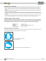
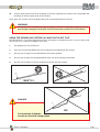
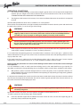
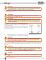
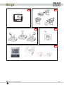
INSTRUCTION AND MAINTENANCE MANUAL
TABLE OF CONTENTS
SECTION INTRODUCTION
CHAPTER 1
INTRODUCTION
Notices .................................................................................................................................................................... page
Legend .................................................................................................................................................................... page
Who to contact for a problem ................................................................................................................................. page
Identification plates .................................................................................................................................................. page
Technical specifications ......................................................................................................................................... page
Specified use ........................................................................................................................................................... page
General safety regulations ..................................................................................................................................... page
General safety regulations ..................................................................................................................................... page
6/44
6/44
7/44
7/44
8/44
8/44
8/44
9/44
Prohibitions .............................................................................................................................................................. page
10/44
SECTION HANDLING
CHAPTER 2
HANDLING
Transporting the machine ....................................................................................................................................... page
Storing the machine ................................................................................................................................................ page
Used materials ........................................................................................................................................................ page
12/44
13/44
13/44
SECTION INSTALLATION
CHAPTER 3
2/44
INSTALLATION
Installation instructions ............................................................................................................................................ page
16/44
Irrigating on land that is not flat ............................................................................................................................... page
17/44
The drawings and the technical data are R.M. S.p.a. - © R.M. S.p.a. - Revision 01.01.2007
SECTION OPERATOR
CHAPTER 4
USING THE MACHINE
Operating conditions ............................................................................................................................................... page
Unwinding the hose ................................................................................................................................................. page
Machine drive and speed adjustment .................................................................................................................... page
Automatic speed compensation ............................................................................................................................. page
Fast hose emptying and rewind ............................................................................................................................. page
Using and regulating the sprinkler .......................................................................................................................... page
Operating instructions for the VDO digital tachometer .......................................................................................... page
Calibration of VDO instruments .............................................................................................................................. page
20/44
22/44
25/44
25/44
26/44
26/44
27/44
30/44
SECTION MAINTENANCE
CHAPTER 5
MAINTENANCE
General maintenance regulations .......................................................................................................................... page
Routine Maintenance .............................................................................................................................................. page
32/44
32/44
SECTION DIAGNOSTIC
CHAPTER 6
SERVICING
Servicing instructions .............................................................................................................................................. page
34/44
Trouble-shooting ..................................................................................................................................................... page
34/44
SECTION SPARE PARTS
CHAPTER 7
SPARE PARTS
Spare parts .............................................................................................................................................................. page
40/44
3/44
INSTRUCTION AND MAINTENANCE MANUAL
4/44
The drawings and the technical data are R.M. S.p.a. - © R.M. S.p.a. - Revision 01.01.2007
INTRODUCTION
PART I
Section 1: Introduction
5/44
INSTRUCTION AND MAINTENANCE MANUAL
NOTICES
This Operating and Maintenance Manual is an integral part of the sprinkler system and must follow the machine
whenever sold to another owner or transferred among farms.
The manual should be kept carefully, read and placed readily at the disposal of all persons involved with it.
In particular, this manual must be read carefully and fully understood by the machine operators and the people
responsible for safety on the farm.
In tune with the overall design of the machine, this manual has been prepared in complete compliance with
European Union directives, EEC 89/392, EEC 91/368, EEC 93/44 and EEC 93/68 (Machinery Directives).
Furthermore, the manual has been prepared in compliance with the latest regulations and legislation concerning
hygiene and safety in the work place published under EEC Directive 89/391.
LEGEND
The symbols detailed below have been adopted in this manual to warn the reader of potential danger to persons
or risk of damage to the machine.
There are two types of symbol:
Danger symbols: are triangular and are used when an operation executed incorrectly can cause serious personal injury.
Warning symbols: are round and used to forbid specified operations to prevent the machine malfunctioning.
6/44
DANGER
Danger of serious personal injury from moving parts.
DANGER
Generic danger
WARNING
Generic warning
The drawings and the technical data are R.M. S.p.a. - © R.M. S.p.a. - Revision 01.01.2007
WHO TO CONTACT FOR A PROBLEM
When the need arises, the customer can contact our Technical Assistance Service by calling the following
numbers:
In ITALY
from abroad
0521 872321
++39 0521 872321
This service offers the customers the solutions to the various problems that can crop up or will provide an on-site
visit by a specialist Service Engineer.
Many technical problems can be solved by very minor service work. We, therefore, recommend reading this
Manual carefully before contacting our Technical Assistance Service.
IDENTIFICATION PLATES
Identification plates and stickers are especially important down the years since they ensure that the manufacturer
can supply the customer, quickly and correctly, technical information and support services of every kind.
Do not modify or remove the information needed to identify the machine. The actual identification data are
indelibly stamped and engraved on a plate. These data comprise everything needed to recognise the machine
and should be included in correspondence between the user and the manufacturer-e.g., when asking for Technical
Assistance, ordering spare parts, etc.
IT IS ABSOLUTELY FORBIDDEN TO REMOVE OR TAMPER WITH THE IDENTIFICATION PLATE.
The following data are stamped on the plate:
Essential data to be specified in all correspondence between user and manufacturer:
MACHINE MODEL
This identifies the model of the machine, the diameter (in
mm) and length (in m) of the hose.
YEAR OF CONSTRUCTION
Specifies the year the machine was built.
S.p.a.
43010 S. Quirico di Trecasali
(Parma) - Italy
MACHINE MODEL
YEAR OF CONSTR.
SERIAL NUMBER
Specifies the machine’s Serial Number.
SERIAL NUMBER
The machine’s Identification plate is located on the right side of the machine (looking at the machine
from the front drawbar).
Section 1: Introduction
7/44
INSTRUCTION AND MAINTENANCE MANUAL
TECHNICAL SPECIFICATIONS
- ENVIRONMENTAL SPECIFICATIONS
- Operating temperature range
min. +10°C max. +40°C.
- NOISE LEVEL
Due to its very nature, the machine is not noisy.
- SAFETIES
The machine is complying with European Union Directives:
EEC 89/392 dated 16/6/89; EEC 91/368 dated 20/6/91; EEC 93/44 dated 14/6/93; EEC 93/68 dated 22/7/93
(machine directive); EEC 89/391 (work site safety and hygiene).
- SPECIFIED USE
The RM sprinkler systems: Super-Rain 540 are machines used to irrigate any kind of crop provided they are
supplied with water under pressure.
Commissioning and operating the machines is extremely simple. However, for correct use of the machine and
fully observance of safety regulations, this manual must be read carefully and fully understood.
We recommend commissioning your machine following the instructions in this manual step by step.
FUNCTIONING
The machine described in these pages is a hose-reel irrigation machine.
It operates by irrigating the soil with jets of water. When the machine is operating, the water is led through a
turbine that operates the central motor that rewinds the hose and the return of the rain gun carriage.
GENERAL SAFETY REGULATIONS
Safety warnings and notices, in addition to specific notices, have been used in this manual to call operator and
servicemen attention to potential dangers stemming from improper use of the machine.
THE INSTRUCTIONS SUPPLIED DESERVE YOUR COMPLETE ATTENTION AND THE ONE OF YOUR
PERSONNEL TOO.
- Follow the safety prescriptions given on the machine and in this manual. Do not modify the safety devices. Use
the machine in full compliance with its operating instructions.
- Failure to observe safety prescriptions and/or improper use of the machine can cause serious injury to people
and domestic animals or damage to property.
- The instructions and safety notices are not intended to take the place of current safety regulations. They are
intended to integrate these latter and encourage their application.
- An efficient machine is a safe machine and hence the importance of following the maintenance schedule
meticulously.
- Safety notices do not, by themselves, eliminate danger!
- All the information and notices given in this manual do not refer solely to factory new machines but are usually
applicable also to second-hand machines.
8/44
The drawings and the technical data are R.M. S.p.a. - © R.M. S.p.a. - Revision 01.01.2007
GENERAL SAFETY CONDITIONS
When the machine is put on work for the first time and at start up each day, the automatic cycle, the normal work
cycle and, in fact, whenever the machine is used, the following general safety conditions must be applied:
- Before starting the machine, read this manual completely and carefully and apply all the safety prescriptions it
details.
- Publicise the contents of this manual with all the people who work with the machine and also with those in
charge of safety matters in general.
- Observe general work site hygiene and safety regulations, industrial accident prevention regulations and the
prohibitions posted by the manufacturer of the machine to protect people from injury and the machine from
damage.
- Do not become over-confident in the use of the machine. Always pay complete attention to what you are doing.
Before confirming an operation, check to make sure that everything is in perfect working condition.
GENERAL SAFETY REGULATIONS
It is very important for the user to observe meticulously all industrial accident prevention regulations.
Furthermore, notices should be affixed to the sides of the machine to ensure immediate visual
identification of dangerous conditions. These notices should have the following specifications:
TRIANGULAR
ROUND
RECTANGULAR
To identify danger
To identify prohibited/obligatory actions
To give information
PERSONAL PROTECTION EQUIPMENT
When you are working on or near the machine, installing it or during routine maintenance and regulation, observe
general industrial accident prevention regulations and, in particular:
Do not work with your bare hands.
Wear adequate gloves.
Wear safety footwear (with steel reinforced toe-cap).
Section 1: Introduction
9/44
INSTRUCTION AND MAINTENANCE MANUAL
PROHIBITIONS
The following prohibitions must be observed when operating the machine:
•
•
•
•
•
•
•
•
•
•
•
•
•
•
•
•
•
•
•
•
•
•
•
•
•
Do not tamper with or cut out safety devices.
Do not inspect the machine while it is running.
Do not sit on the protective casings.
Do not lean on the machine when it is running.
Do not sit on the components making up the machine.
Do not use the machine or parts of it for uses other than those detailed in this manual.
Regulations to the machine must be done by a single person and while the work is under way, unauthorised
people must be kept away from the machine.
Do not modify and/or move parts of the machine.
Do not add other equipment to the machine.
Do not use any kind of solvent, such as alcohol, petrol or thinner to clean any surface on the machine.
Do not allow personnel whose qualification level is different from those detailed in the section on «MACHINE
OPERATORS» to perform any kind of work on the machine.
Keep hands, arms and, in general, all parts of the body, away from moving parts.
When trouble-shooting and fixing any kind of malfunction on the machine, apply all the precautions described
in this manual. These, in fact, are designed to prevent injury to people or animals and damage to property.
Before beginning any job, concentrate fully on what you are doing.
Always be very wide awake and ensure that your reflexes are quick and sharp. This is extremely important for
the operator.
Do not operate the machine or its equipment under the influence of alcohol, drugs or medicine.
Operator clothing must be as suitable as possible. In other words, not too loose nor too tight. Do not wear
flapping or dangling items that could become trapped in moving parts.
Do not wear belts, rings, bracelets, chains, etc.
This machine must not be used by people with physical handicaps.
This machine must not be used by people under 18 years of age.
It is absolutely forbidden to use the rewinding crank handle improperly (before using it, read carefully the
instructions on page 22/44 and 26/44).
Do not aim the sprinkler jet towards roads, railway lines and near high voltage lines.
During work transfers, do not exceed a speed of 15 km/h.
Do not use the machine of a gradient of more than 3%.
Do not disconnect the feed hose when the water is under pressure.
IMPORTANT
RM Spa declines any and all liability for defects, injury to people, damage to property and
any loss by failure to observe the safety regulations and prohibitions detailed above.
10/44
The drawings and the technical data are R.M. S.p.a. - © R.M. S.p.a. - Revision 01.01.2007
HANDLING
PART II
Section 2: Handling
11/44
INSTRUCTION AND MAINTENANCE MANUAL
TRANSPORTING THE MACHINE
Use adequate steel wires to load or unload the sprinkler machine. Use the specific hoisting lugs (one or two on
each side of the machine's chassis).
Follow these steps to hoist the machine:
1.
A portal crane or other lifting equipment with adequate lifting capacity should be available so that you can
hoist the machine from above.
RM self-propelled sprinklers have not been engineered to be lifted using forklift trucks and therefore,
this operation must not be attempted.
2.
Hook the machine to the lifting equipment using wires adequate for the weight to be lifted (refer to the
Table below).
MACHINE
540 (63/175)
3.
WEIGHT kg (empty)
650
WEIGHT kg (water)
376
WEIGHT kg (with water)
1026
Lift the machine up slightly and check to make sure that the load is balanced. In particular, the
sprinkler skid must not be installed because, if it is, the load will be unbalanced.
WARNING
Hoist the machine only if the angle between the lift wires is less than 40° or 20° to the
vertical.
4.
When hoisting the machine pay special attention to make sure that the steel wires do not damage the
machine. In particular, make sure that the two sides of the hose reel are not squashed.
DANGER
All loading and unloading operations must be done exclusively by expert and authorised
personnel.
RM Spa declines any and all injury to people or damage to property caused by incorrect
handling of machine parts or their incorrect installation.
12/44
The drawings and the technical data are R.M. S.p.a. - © R.M. S.p.a. - Revision 01.01.2007
STORING THE MACHINE
If the machine is not installed immediately and needs to be stored temporarily, it must be stored in a dry covered
place.
DISPOSING OF THE COMPONENTS
The estimated working life of the machine is 25,000 work hours under normal conditions. At the end of the
machine's working life, the owner must dispose of it in full compliance with current regulations. First, all lubricants
should be emptied out and all the parts cleaned. Then the various materials making up the machine should be
separated.
Each type of material can then be disposed of in compliance with the regulations current in the country where
the machine is operated in.
WARNING
During disposal, observe all regulations in force in your country. Store polluting material
such as oil and solvents in metal containers.
MATERIALS USED IN THE MACHINE:
MATERIAL
USE
PAINTED METAL
Chassis
HOT GALVANISED IRON
Rain gun skid
NICKEL PLATED IRON
Fittings
POLYETHYLENE (PEMD)
Hose
RUBBER
Tyres, sleeves
CAST IRON
Gear unit box, hose slide
Section 2: Handling
13/44
INSTRUCTION AND MAINTENANCE MANUAL
14/44
The drawings and the technical data are R.M. S.p.a. - © R.M. S.p.a. - Revision 01.01.2007
INSTALLATION
PART III
Section 3: Installation
15/44
INSTRUCTION AND MAINTENANCE MANUAL
INSTALLATION INSTRUCTIONS
1.
Before placing the machine on the ground, install the wheels and the drawbar fixing them with the
appropriate bolts (pos.2 photo A).
The rear support legs (pos. 3, photo A) must also be inserted in their housings as shown in the figure.
The legs cannot be inserted if the machine has been lowered to the ground.
Once the machine has been towed by the tractor for about 1 km, the tightening performance of the following
parts should be checked: wheel retaining nuts, axle fixing bolts.
2.
Install the rain gun skid as shown in the photograph. Beforehand, use a file to remove any burrs left by
the galvanising process. Put the legs (pos.1 photo C) in their house 7 photo C.
The wheel track (measured between wheel centres) must not be less than 1.4 m. If the carriage is used with a
lesser track the stability of the machine could be prejudiced.
3.
Pull out about 2 m of hose (pos. 2 photo C). Refer to the section on “USING THE MACHINE” for complete instructions on how to do this.
Couple the flange (pos. 3 photo C) to the carriage, after having inserted the rubber seal.
4.
Install the machine’s rain run fixing it to its skid (pos. 5 photo A).
The tapped fitting on the skid carriage must be covered with Teflon or other sealing material before
screwing down the rain gun.
Tightening performance on the rain gun must be extremely firm to prevent it from working loose during
operation. Tighten it using a socket wrench.
5.
Make a preliminary regulation of the rain gun’s sector (using pos.4 photo B) and install a nozzle sized for
the water supply volume.
6.
Bring the sprinkler skid carriage to the disengage bar using the crank handle in the machine’s equipment
kit (pos. 1, photo D). Check that the stop bar (pos.2 photo E) passes under pos.3 photo E.
At this point, raise the carriage using the mechanical jack (pos.1 photo E).
CAUTION
It is essential when jacking up the carriage to disengage the stop dog that meshes with
the reel drive gear (pos. 2, photo D).
DANGER
If the stop dog is not disengaged when the carriage is jacked up, the machine can be
severely damaged.
16/44
7.
Check if the swivel plate locking pin is in its seating (pos. 1, photo F).
8.
Check if the stop dog (pos. 1, photo D) is inserted into the reel drive gear.
9.
Check the inflation pressure on the machine’s tyres. If necessary fill them to the correct pressure of 3 bar
= 45 Psi.
The drawings and the technical data are R.M. S.p.a. - © R.M. S.p.a. - Revision 01.01.2007
10.
Check to make sure that one of the couplings on the hose supplied in the machine’s kit is compatible with
the fittings on the line supply water to the machine.
At this point, the machine can be coupled to the tractor and transported to its work site.
WARNING
RM Spa declines all liability for injury to people or animals or damage to property caused
by oversight or improper installation and connection work carried out on the machine.
USING THE SPRINKLING SYSTEM ON LAND THAT IS NOT FLAT
The RM sprinkler is a machine designed to work on flat land but, in exceptional cases, it can be used on hilly
land. In this case, a number of conditions must exist:
1.
The gradient must not exceed 15%.
2.
There must not be large differences in level along the route followed by the rain gun.
3.
The rain gun carriage must be perpendicular to the down gradient.
4.
The rain gun carriage must be perpendicular to the axis of the reeling in drive motor.
5.
The rain gun carriage must always be downstream from the reel carriage;
MAX 15%
NO
DANGER
NO
It is absolutely forbidden
to work on land with abrupt drops
Section 3: Installation
17/44
INSTRUCTION AND MAINTENANCE MANUAL
18/44
The drawings and the technical data are R.M. S.p.a. - © R.M. S.p.a. - Revision 01.01.2007
USING THE MACHINE
PART IV
Section 4: Using the machine
19/44
INSTRUCTION AND MAINTENANCE MANUAL
OPERATING CONDITIONS
1.
The machine must be towed by a tractor whose weight is greater than or at least equal to the weight of the
machine plus the weight of the water inside the hose. For more details on this refer to the section on
“TRANSPORTING AND HANDLING THE SPRINKLER”.
2.
The Highway Code current in the country of use must be followed whenever the machine is transported
on road.
Note that RM sprinkler machines are not certified for on-road operation.
The machine must be fitted with a rear light assembly connected to the tractor’s electric system and attached on
the back of the machine, i.e. on the rain gun skid carriage.
WARNING
RM Spa recommends all users of its equipment to obtain information on the current
Highway Code in force in the country where the machine will be used. RM Spa declines
all liability for injury to people or damage to property caused by road accidents.
Tractor speed when towing RM equipment must not exceed 15 Kph. Speed higher than
this can cause the sprinkler’s tyres to explode with serious consequences for operator
safety or that of other users of the road.
3.
Water supply to the machine must be done by means of a pressurised water line (supplied by the mains
water supply, a pump connected to a tractor, an electric pump, etc.).
It is essential that the operating pressure at machine intake is between 3 and 12 bar (pos. 1, photo H) at the
volume indicated in the rain gun’s user Chart. Pressure must be constant and at full operating volume, must not
vary by more than 1 bar.
If the supply water line is subject to the so-called “hammer effect” (this is often in the case of water company
supply lines), a pressure relief valve set at 11-12 bar should be installed at machine intake.
Failure to take this precaution can cause serious damage to the machine and also be a source of danger
to the operator.
It is recommended to check to make sure that the fittings used on the water feed line are good quality. It is
absolutely not advised to change the fittings factory installed on the hose with others available on the market.
4.
RM sprinkler systems have been designed to have a centre of gravity as low as possible. However, it is
good standard practice to pay special attention when operating or simply towing on rough roads, gradients
or bad surfaces in general.
It is important to remember that, once the machine has been used for the first time, the water in the hose will not
only increase the weight of the machine but also shift its centre of gravity upwards. This means that there is an
increased risk of the machine tipping up or over.
WARNING
Do not operate with the machine inclined at an angle on gradients higher than 3%. This is
extremely dangerous.
Position the machine at its work area. The sprinkler will appear as illustrated in Photo A.
To make it operational, the following steps will be required:
A.
20/44
Lower the drawbar support foot and detach the tractor. Check to make sure that the support leg (pos. 9,
photo A) is firmly anchored on the ground.
The drawings and the technical data are R.M. S.p.a. - © R.M. S.p.a. - Revision 01.01.2007
CAUTION
The lowering of drawbar support foot has to be carried out by only one person who will
have to make sure that no obstacles lie under the bar axle. RM Spa declines all liability for
damages occured incase the above prohibition has not been respected.
B.
Remove the pin on the rotation (pos. 1 photo F) and then rotate the hose wheel by pushing on the back side
of the rain gun carriage.
WARNING
On some models, before turning the turntable, it is necessary to keep away the Bauer
plug mounted on the double water inlet.
WARNING
On the machines without hydraulic rotation, before keeping away the pin, it is necessary
to pay attention to the accidental rotation of the turntable (due to an eventual slope of the
machine on a side). In this case keep the safety distance and keep Your body and limbs
away from the machine.
Orient the reel for the hose winding so as to have it perfectly in line with
the direction to which the hose unwinds; to carry out this operation, use
the reel side as reference.
It may happen to unwind the hose on grounds not wholly straight; in any
case, it is necessary to have the first 50/60 m of the hose completely in
line with the reel (see picture).
YES
C.
NO
After having oriented the reel, secure it by the pin into one of the special stop dogs; to obtain the correct
machine inclination use it in one of the reel drive gear positions.
CAUTION
After securing the wheel at the desired inclination, make sure that the front end of the rain
gun carriage is not too close to one of the two machine tyres since the tyres themselves
could be damaged during the following rewinding.
This is mainly reccomended for those models where the hose, when completely winded, ends on one of the reel
sides. Lower the back support feet to the ground and fix them by the special pins (pos. 3 picture A and pos.2
picture G).
CAUTION
The lowering of the drawbar support foot has to be carried out by only one person who
will have to make sure that no obstacles lie under the bar axle. RM Spa declines all liability
for damages occured in case the above prohibition has not been respected.
Turn the handwheel (pos. 1 picture G) so as to secure the support foot to the ground.
CAUTION
In order to safely anchor it, the surface where the foot rests has to be firm, the land has to be
solid.
Section 4: Using the machine
21/44
INSTRUCTION AND MAINTENANCE MANUAL
The support legs must not be cranked down with the handle more than 15 cm. If this
has to be done, first change the hole in the bracket.
Regulate carriage track with the fixing bolts (pos. 7, photo C) for the wheel width required (the track must
never be less than 1,4 m).
To ensure good rain gun skid carriage return, the hose must always be centred between the two wheels.
Lower the carriage with the wheel on the hydraulic pump (pos. 1, photo E). Check to make sure that the
bracket (pos. 6, photo C) is released from the carriage and that the carriage can be towered without bumping
into the bracket.
WARNING
If the level difference between the rain gun wheels and the machine wheels is more than
30 cm, the sprinkler machine will have to be repositioned to eliminate this condition. It is
also important to check to make sure that the rain gun skid wheels are not in a dip when
the carriage contacts the disengage bracket.
Check to make sure that all the operations detailed in the sections above have been executed
correctly, the machine is ready to have the sprinkler hose reeled out.
REELING THE HOSE OUT
Follow these steps to reel the hose out correctly:
1.
Disengage the ratchet stop dog by turning it 180° counterclockwise (as shown in pos. 2, photo D). To
disengage the stop dog easily, turn the PTO slightly counterclockwise with the handle (pos. 1 photo D).
2.
Position the gear drive lever (pos. 7, photo H) pulling it towards right (that is towards the trolley pos.4 photo A).
3.
Braking function regulation should always be with the handwheel (pos. 6, photo H) with very slight adjustments
per time before starting to reeling the hose out.
If it is necessary to do a further adjusting during the hose unwinding, use the same handle, having care
not to brake too much.
Completely release the brake at end of unwinding before starting rewinding.
4.
Hook up the rain gun trolley chain (pos. 8, photo C) to the tractor.
5.
Unreel the hose by towing the rain gun skid carriage in a straight line and, more importantly, at a low speed
(max. 3 Km/h).
WARNING
IT IS ABSOLUTELY FORBIDDEN to accelerate abruptly, slow down suddenly or change gear
when unreeling the hose.
If this prohibition is not observed, there is a real risk of over-running the hose and breaking it.
Leave at least one and a half turns of hose on the reel. If the machine cannot be seen at the end of
the unreeling, have a second operator give a clear and certain signal that the hose is approaching the
end of the reel. This will prevent the hose from being detached from the machine.
22/44
The drawings and the technical data are R.M. S.p.a. - © R.M. S.p.a. - Revision 01.01.2007
6.
When the hose has been unreeled, before going back to the machine, make sure that the rain gun carriage
is correctly positioned (using sectors pos.3 photo B).
7.
Reinsert the stop dog turning clockwise (pos. 2, photo D) and make sure that the turns of hose still on the
reel are nicely close together (pos. 1 photo L).
If they are not, bring them together and tension them using the crank on the PTO (pos. 1, photo D).
DANGER
Do not use this crank when the hose is being reeled in.
DANGER
Do not begin to reel in the hose if the turns are not perfectly next to each other on the
reel. There is a real danger of getting your hands caught and crushed by the coils. Be
extra careful and vigilant whenever working on the reeled in hose.
Completely release the brake using pos.6 photo H.
8.
Connect the delivery coupling to the water feed line.
If the fittings are very stiff, lubricate the rubber seal on the ball joint.
You can now feed in the pressurised water supply by opening very slowly the supply valve and accelerating
very slowly the feed pump motor.
Wait until the hose fills completely with all the air vented from the water line. Then increase the water supply to
the operational level.
Leave the machine with the lever (pos. 7 photo H) in the position used to unreel the hose, carry out a sprinkling
cycle without reeling in the hose.
For best results, leave the lever in this position for at least 15 minutes. Then move the lever to the position for
reeling in the hose.
DANGER
By standers must be kept out of the machine’s working range for all irrigation stages.
Section 4: Using the machine
23/44
INSTRUCTION AND MAINTENANCE MANUAL
To give you a clearer vision of what is meant by “safety distance”, the illustration below summarises the
distances to be observed during the various stages.
B
A
C
Three operational areas are shown:
A=
The rain gun carriage: this is where irrigation actually takes place. The minimum distances are 5 m at
the sides and 3 m from the back.
B=
Hose: the water transfer area is not dangerous but it is best to maintain a safety distance of 2 m.
C=
The sprinkler machine: the danger is higher here and a safety zone of 5 m should be maintained
around it.
24/44
The drawings and the technical data are R.M. S.p.a. - © R.M. S.p.a. - Revision 01.01.2007
MACHINE DRIVE AND SPEED ADJUSTMENT
Engage the drive lever (Pos. 7, photo H) by pulling it towards left and use the by-pass to engage the desired drive
speed (pos. 3, photo H).
To adjust the speed: slacken off knob (pos. 2 photo H), engage the manual by-pass valve (pos. 3, photo H). Set
the speed as required and then re-tighten knob (pos. 2, photo H) to lock the machine at that speed.
If the obtained speed is always too fast or too slow, a further adjusting must be made using the
transmissionm chain positioned under safety cover (pos.14 photo H). For this adjusting stop water feeding
to the machine (so that pressure indicated in manometer pos.1 photo H becomes "zero"), brake with the
handle pos.6 photo H firmly closing clockwise; open safety protection pos.14 photo H lifting it up. Now, in
order to decrease the speed, move the chain pos.9 photo H to the smaller diameter gorge of the pulley
no.10 and to that of bigger diameter of pulley no.11 photo H. Do the contrary to increase the speed.
IMPORTANT
ATTENTION! THE ABOVE OPERATION MUST BE MADE ONLY WHEN THE MACHINE IS
STOPPED. DON'T TRY TO CHANGE THE CHAIN WHILE THE MACHINE IS WORKING: IT CAN
BE DANGEROUS!!
It is good standard practice to make the definitive reeling in rate setting after the lever has been engaged for some
minutes (pos. 7, photo H) so that the hose has been pit into traction.
The working pressure and reeling in rate can be read off the instruments on the machine (pos. 1 and 4 photo H).
Refer to page 27/44 for instructions on the VDO digital tachometer.
IMPORTANT
When the machine is operated at maximum speed, the load loss inside the turbine
increase considerably but this is normal.
AUTOMATIC SPEED COMPENSATION
The machine has an automatic speed compensation system that permits the rain gun carriage to be reeled in at
a constant speed throughout the irrigation work.
This regulation is done by means of a control operated by a probe on the hose at the back of the machine and this
in turn acts on the main by-pass valves.
A machine with 175 meters of hose set for a reel in rate of 20 m/h must have an irrigation time of 8 h 45.
If there are more hours (10), there is very little compensation and the control lever must be moved upwards using
the holes on the lever (pos. 12, photo H). If there are less hours (7), compensation is high and the lever will be
moved downwards using the same reference holes.
Section 4: Using the machine
25/44
INSTRUCTION AND MAINTENANCE MANUAL
FAST HOSE EMPTYING AND REWIND
To empty the hose, it should be unwound for not more than 50% of its length following the instructions given in the
section on “UNREELING THE HOSE”.
Reel the hose back with the PTO (pos. 8 photo H) with the gear unit lever in the disengage position (lever pos. 7
photo 7 towards right) and remove the drain plug on the carriage.
If the drain plug is not installed, remove the rain gun.
The hose must be reeled in exclusively with the PTO running at 540 Rpm at low speed and a sufficiently long PTO
shaft for max. 30 Hp transmitted power.
When the rain gun carriage is close to the end travel bracket and the hose reeled out 1 m, it must be reeled in
completely with the requisite crank handle (pos. 1, photo D).
WARNING
Reeling in with the PTO shaft will not stop automatically and therefore this operation
must be done with the utmost care and attention.
Do not use the crank handle when the hose is reel out for more than 1 m because handle
spring back, caused by the elasticity of the hose, could cause serious injury to operator
limbs.
USING AND REGULATING THE SPRINKLER
Follow meticulously manufacturer instructions. You will find these in the spare nozzle box.
DANGER
To ensure your safety, do not aim the water jet towards high voltage lines. Always check
to make sure that the jet is never directed towards houses, paved roads, electric cabins,
etc.
You will be held liable for any damage done if there is a power down or other problems
caused by your irrigation work.
26/44
The drawings and the technical data are R.M. S.p.a. - © R.M. S.p.a. - Revision 01.01.2007
OPERATING INSTRUCTIONS FOR THE VDO DIGITAL TACHOMETER
The VDO digital speedometer installed on the machine has been factory programmed. This instrument can read
instantaneously the hose rewinding rate and show this on the display as meters per hour.
The display also gives the first decimal for the speed and the current time. Speed range is from 5 to 140 m/h.
This instruments works with a 3V battery (Type CR 2032/Sony) with a working life of around 2 years.
The instrument is automatically switched on when the hose is reeled in or out. To prevent the battery from be run
down, the liquid crystal display will automatically switch off about 5 minutes after the machine is stopped.
FUNCTIONS AND OPERATION
ACTUAL SPEED DISPLAY
The digital tachometer displays the temporary rewinding speed. This function is always activated on the VDO
SPRINT instruments (oval MODE key and red round SET key) and on the VDO CYTEC C05 instruments (one
key only).
To display the current time with VDO SPRINT instruments, press MODE key, for at least 2 seconds. With the
VDO CYTEC C05 instruments, press once or more the key to display CLK. The display will show the current
time, the symbol CLK and the temporary rewinding speed.
With the VDO EURO instruments (rectangular MODE key), the temporary speedy is activated only when the
symbols SPD and CLK besides the current time are displayed; if this is not the case, they can be activated by
pressing MODE key until both symbols are displayed.
The displayed speed is perfectly correct only when the pipe is completely unwound until the last layer; when the
pipe is completely wound, the displayed speed is slightly low than the real one.
CHANGING THE BATTERY AND PROGRAMMING THE INSTRUMENT
If the battery has to be changed (display off), follow these steps:
1. Remove the display from its mounting as shown in figure 2. Use your right hand to push the instrument
down and use your left thumb to press the black knurled button under the instrument to release it from its
mounting.
On VDO Cytec C05 puss slightly the head and turn it counterclockwise, then remove the head from its
holder.
2. Use a coin to unscrew the battery enclosure cover. Remove the battery and replace it with the new one
(Fig.3).
Insert the new battery with the positive pole towards the top and replace the cover. When the battery is
changed the data remain in the memory for about 15 seconds.
WARNING! Batteries are special waste material to be disposed of correctly.
3. If the data are cancelled, reprogram the instrument as follows:
VDO EURO AND VDO SPRINT INSTRUMENTS:
Press MODE key until the ODO function appears on the display. Press SET key for at least 3 seconds. Insert the
requisite number for the machine model (see table at page IV.12).
Press MODE key to select the first number on the right of the display. Set it with SET key. Follow this process for
all the numbers until they no longer flash.
On the model VDO SPRINT, press again SET key for at least 6 times, until the temporary rewinding speed is
displayed, then press MODE key for at least 3 seconds to display the current time too.
Section 4: Using the machine
27/44
INSTRUCTION AND MAINTENANCE MANUAL
VDO C05 CYTEC INSTRUMENTS:
1) Press some times the key to display ODO and then press the key for at least 3 seconds.
2) Now m/h and km/h are gleaming alternatively; when km/h is displayed, press the key to fix it.
3) The instrument is now automatically proposing the programm number (4 digits). The first digit on right starts
gliding; when the correct number is displayed, press the key to confirm it. Do the same procedure for all other
digits.
4) Now the display shows another number (5 digits); repeat the above procedure until all digits are setted on
ZERO.
5) At the end, take the instrument on CLK again by pressing the key.
SETTING THE CLOCK
To set the clock on the model VDO SPRINT, press MODE key for at least 2 seconds until CLK is displayed; press
SET key for at least 3 seconds, then press MODE key again to choose the 12 or 24 hours time and fix it with SET
key; press MODE key until the desired time is displayed; then press SET key to fix the exact time.
To set the clock on the model VDO EURO, press MODE key until the symbol CLK is displayed (clock setting);
press SET key for at least 3 seconds, then press MODE key again until the desired time is displayed. Press SET
key to fix the exact time.
On model VDO CYTEC C05, press the key once or more to display CLK. To modify the actual time, already
displayed, press the key for some seconds until the time only is dispalyed. Now the digit indicating hour is gliding.
When the correct number is displayed, press the key to fix it and repeat the same procedure for the minutes,
which have started to glide too. At the end, take the tachometer on CLK again by pressing the key.
TROUBLE-SHOOTING THE VDO SPEEDOMETER
Problem:
The speed is not displayed or the function symbol ((1)) doesn’t sparkles while the machine is
working.
Remedy:
a) Check if the wire between the transmitter and mounting has been damaged or broken.
Check if it has been crimped.
b) Check if the display unit has been pushed all the way down in its mounting to make a
perfect contact. Check if the contacts are clean.
For VDO Cytec C05: position the head of the computer on the support and turn until You
can hear a “CLICK”.
c) For VDO Cytec C05: check the exact distance between the sensor and the magnet and
adjust the distance between them, if necessary.
Problem:
Incomplete numbers and letters appear on the display.
Press the AC button on the back of the unit (Fig. 4) to cancel all the settings memorised. Reprogram
Remedy:
the instrument following the instructions given above.
28/44
The drawings and the technical data are R.M. S.p.a. - © R.M. S.p.a. - Revision 01.01.2007
1
2
3
4
5
Section 4: Using the machine
29/44
INSTRUCTION AND MAINTENANCE MANUAL
CALIBRATION OF VDO INSTRUMENTS:
Machine
540
Inside diameter
of drum
Calibration
with 3 magnets
Calibration
with 1 magnet
750
2367
1183
(with pulley)
30/44
550
870
2126
560
870
2090
1568
570
1040
2232
1674
580
1240
2730
581
1240
2730
581 chain
1240
590
1420
2773
600
1420
2690
600
1320
1553
690 chain
1320
1379
690 chain
1340
1390
690 chain
1420
1415
700
1524
2397
700
1340
2265
790
1340
800
1700
2591
1541
800
1500
2476
1473
890
1500
1473
890
1700
1541
900
1920
2999
1813
900
1700
2920
1736
990
1700
Major
1480
Major
1540
Major
1620
2870
1708
Major
1700
2920
1736
1618
1441
1594
1347
1347
1715
2788
1659
1680
The drawings and the technical data are R.M. S.p.a. - © R.M. S.p.a. - Revision 01.01.2007
MAINTENANCE
PART V
Section 5: Maintenance
31/44
INSTRUCTION AND MAINTENANCE MANUAL
GENERAL MAINTENANCE REGULATIONS
All maintenance and repair work must be done by expert and specialist personnel.
All service engineers must work in full compliance with industrial accident prevention regulations. They must
wear suitable protective clothing. In this context, refer to the section on “GENERAL SAFETY NOTICES”, part of
the “INTRODUCTION” to this manual.
MAINTENANCE PLAN
Maintenance to be
effected every:
Description
Product to be used
300 h
Greasing of hoseguide screw
Grease for agricultural machinery
300 h
Greasing of rotation's turntable
Grease for agricultural machinery
300 h
Greasing of wheel's housing - water inlet side
Grease for agricultural machinery
300 h
Greasing of teeth welded to the wheel
Grease for agricultural machinery
300 h
Greasing of ratchet stop dog
Grease for agricultural machinery
see manuf.instruct. Greasing of sprinkler
300 h
Grease for agricultural machinery
Lubrication of by-pass valve's shaft with
manual oil feeder
SAE 90EP/PP 80 oil
300 h
Lubrication of transmission side chain between
wheel and hoseguide with manual oil feeder
Replacement of gearbox oil (check the
SAE 90EP/PP 80 oil
1000 h and
min. every 2 years
level every 300 h)
about 6 lt. SAE 90EP/PP80 oil
1000 h and
Replacement of hydraulic system's oil (only for
min. every 2 years
models with Briggs & Stratton engine with
oil tank)
20 h
about 12 lt HP68 hydraulic oil
Turns multiplying oil of compressor for
emptying (where mounted)
see table on voice "compressor"
CHECKING OF SCREW COUPLINGS (to be effected with a dynamometrical key)
Coupling
Tyres nuts (550-560)
Tyres nuts (570 -> Major)
Screw for fixing of tyres axle
Rotation's turntable
Screws for fixing of gearbox to
the chassis
Screw
delle viti
Key
measurements (mm)
Tightening moment
M14
19
27
22
22
300 Nm
300 Nm
150 Nm
150 Nm
M10
17
65 Nm
WARNING
CHECK TYRES NUTS AFTER 20 H OF WORK.
32/44
The drawings and the technical data are R.M. S.p.a. - © R.M. S.p.a. - Revision 01.01.2007
SERVICING
PART VI
Section 7: Servicing
33/44
INSTRUCTION AND MAINTENANCE MANUAL
SERVICING INSTRUCTIONS
During the machine’s normal working life, the machine can stop or lose its correct regulated settings. In these
situations, follow these steps:
° Refer the matter to an expert service engineer. Only a service engineer can deal with these kinds of
problems.
° The service engineer should identify the type of problem from a reading of the pages below on Troubleshooting the machine. Once the problem is identified, he can find the right solution and put the problem
right.
The machine may have problems that are more serious than expected.
Once you have identified the problems and checked the solutions offered in the TroubleShooting pages below, if the work cannot be done under perfectly safe conditions, refer
the matter to your nearest RM Technical Assistance Centre.
TROUBLE-SHOOTING
The following are some typical problems that crop up when the machine is working under normal conditions.
Read this section carefully since it will provide useful remedies to solve these kinds of problems.
PROBLEM
REMEDY
When the hose is being pulled by the tractor to unwind it, the hose will not come out.
Disengage the stop dog (pos. 2, photo D) from the chain (Models 700, 800, 900, Major, 890,
990) or from the reel drive gear (Model 550, 560, 570, 580, 590, 600).
PROBLEM
When the hose is being pulled by the tractor to reel it out, there is very strong
resistance.
Check if lever (pos. 7, photo H) is disengaged (downs for models 550, 560, 570 and towards
the rain gun carriage for all other models), raise the rain gun carriage with the tractor lift so
that the weight is on the tractor’s rear axle. Disconnect the hose, remove the round plug (if
installed on the rain gun carriage).
If the resistance is still high: Slacken off the brake even more (handwheel pos. 6, photo H) and
reduce the tractor speed to 5 kph.
REMEDY
PROBLEM
REMEDY
The gear unit runs hot during unreeling
Reduce tractor speed to 5 Kpm. A slight heating up of the gear unit box is normal during hose
unreeling.
PROBLEM
Water reaches the machine but does not come out of the rain gun or just a small
amount does.
Check the pressure on the turbine gauge. It should be at least 4 bar. Try to increase the infeed water pressure.
If the problems persists: Cut off the water supply and check if there are obstructions in the
intake line (pos. 13, photo H); check the rain gun nozzle for foreign bodies. It is good standard
operating practice to unreel the hose completely (especially when the machine is
commissioned or after the winter lay up).
REMEDY
PROBLEM
REMEDY
34/44
Water reaches the machine but the turbine does not turn and does not reel in the hose.
Check if the water volume is sufficient and if the pressure (read from the turbine gauge) is
over 4 bar, follow the procedures outlined below:
A) Operate the turbine by-pass valve (pos. 3, photo H) by pulling it towards the water
in-take (pos. 13, photo H): check if the turbine turns normally checking the plastic
coupling between the turbine and gear unit. If the turbine turns, go on to point C).
The drawings and the technical data are R.M. S.p.a. - © R.M. S.p.a. - Revision 01.01.2007
If the turbine does not turn or does so very slowly:
Install a nozzle 2-4 mm larger on the rain gun (pos. 4, photo A). Try again and check the rain
gun throw. If necessary try another nozzle to get a better throw (if the nozzle is too big or too
small for the water volume, the throw will be shortened. Check on the in-feed gauge (pos. 1
photo H) if the pressure still exceeds 4 bar. If it is less, increase the pressure to reach the
optimum level.
B) If the turbine still does not turn:
Detach the water supply line and dismantle the coupling by removing the four screws on the
flange (pos. 11, photo H).
Check the small orifice (where the black tapered nozzle is inserted) for foreign bodies. Remove
the tapered nozzle and check if the impeller moves easily. To make this check, use a screwdriver
to push up the fin you see in the smaller orifice (where the tapered nozzle was seated before).
If the impeller does not move, remove the eight Phillips screws on the turbine casing, open
the casing and remove the foreign body that is preventing the impeller from turning.
If the impeller still does not move, call your nearest RM Technical Assistance Centre.
C) The turbine turns but the machine does not reel in the hose.
Check if lever (pos. 7, photo H) is perfectly engaged (move it a couple of times) and then
check if the gear lever is set on one of the four speeds.
Try changing speed with a firm quick movement selecting first one speed and then the others.
Make sure you are not leaving the gear lever between two gear positions.
These operations must be done with the turbine supplied with water
under pressure (that is, the turbine is turning).
D) If the turbine turns but the gear unit intake shaft does not move:
Check that the impeller is correctly fixed on the turbine shaft by opening the outside turbine
body.
E) The turbine turns but when the reel in is engaged (pos. 7, photo H) it stops:
- if the problem persists even at the first speed, follows the instructions under A) above.
- if the problem continues after these checks, change the nozzle in the turbine with a
smaller diameter.
When you are turning the PTO, if the force of the handle decreases in one or two points, this
means that the gear unit is damaged. Refer the matter to your nearest RM Technical Service
Centre.
To do this: dismantle the in-feed fitting by removing the four screws on the flange (pos. 11,
photo H). Remove the nozzle and replace it with one with a smaller diameter (it is normally
enough to reduce the diameter by 2-4 mm).
The nozzle used in the turbine is the same type as the one in the rain gun and so check if you
already have one in the machine kit. If the one installed in the rain gun is not the same, it can
be ordered.
F) The turbine turns normally but the gear unit stops after a few turns. Follow the steps
described under point C): If the problem remains, cut off water supply, put the gear lever in
4th gear and hold lever (pos. 7 photo H) engaged. Attach the crank to the PTO and turn it
counterclockwise for two complete turns. When you are turning the PTO, if the force of the
handle decreases in one or two points, this means that the gear unit is damaged. Refer the
matter to your nearest RM Technical Service Centre.
Section 7: Servicing
35/44
INSTRUCTION AND MAINTENANCE MANUAL
PROBLEM
REMEDY
The machine moves or slides on the ground when reeling in the hose
Attach the rear support legs better.
If this does not work, act immediately with the following procedure:
Put the gear lever in 4th (refer to the section “REGULATING REELING IN SPEED”; disengage
the stop dog (pos. 2, photo H); open the by-pass valve to slow down or stop the turbine. Do not
touch lever (pos. 7, photo H). At this point, the reel will turn in the direction opposite to its reeling
in direction. Allow the tension on the hose to slacken off.
When the machine stops, reposition the rear brackets but select a spot where the ground is
more solid and compact.
If necessary, turn the swivel plate to move the reel’s axis in line with the hose.
When the hose is unreeled for more than 3 hours under particularly damp conditions (rain or
very wet ground), when re-reeling it, the hose should be raised above the ground using 10-12
cm thick wooden spacers.
This is very important otherwise there is a real risk of the hose breaking and, consequently,
irreparable damage to the reel . RM Spa declines any liability for damage caused by failure to
observe this standard operating procedure.
PROBLEM
REMEDY
During re-reeling, the hose is badly reeled or is outside the reel.
Follow these instructions for perfect re-reeling:
Unreel the entire hose (the very first time and thereafter once every four unreeling and rereeling cycles). If the hose is partially unreeled, check at the beginning of the work cycle to make
sure that the coils still on the reel are perfectly placed. It is essential that (for at least 50 m from
the machine) that the hose is perpendicular to the axis of the reel. Thus when the hose is reeled
out by the tractor, check to make sure this is the case (if necessary, turn the swivel plate to
achieve this alignment). It should also be noted that, in the first 20-30 unreeling cycles, hose rereeling cannot be perfect until the hose has fully adapted to the reel.
If the problem is not solved after carrying out the steps outlined above, remove the plastic
casing on the side opposite the turbine and with the machine stopped.
Count the number of teeth in pinion installed on the wheel shaft and the number of teeth on the
pinion on the hose slide shaft. Give these numbers (plus the hose diameter and length) to the
RM Technical Assistance Service.
PROBLEM
REMEDY
The rain gun carriage does not return correctly during rewinding.
If the wheels of the rain gun carriage tend to lift off the ground during re-reeling (check this 1520 minutes into the re-reeling cycle), widen the wheel track or add ballast on the sides of the
carriage.
It is always best to have the rain gun carriage working with the right and left wheels at equal
distances with the hose between them.
When the rain gun is used on one side, make a slight furrow in the ground in which the hose will
be held during rewinding.
If the machine is used on hilly land or land that is not completely flat, it is best to place the rain
gun carriage on the lower side so that the machine will take in the hose reeling it from above.
PROBLEM
The hose is oval shaped when the machine is supplied from a well or from the water
mains.
This is caused by two negative effects working together:
° the low pressure normally found in this kind of supply source.
° pressure drops in the supply to levels insufficiently high to operate the system.
Since we can do nothing to remedy the problem of low pressure main supply, due to the inconstant
pressure, the machine should be used at the lowest re-reeling system possible. It is also good
practice to leave the stop dog disengaged (pos 2, photo D) to allow the reel to recover partially
if there is a drop in supply pressure.
REMEDY
36/44
The drawings and the technical data are R.M. S.p.a. - © R.M. S.p.a. - Revision 01.01.2007
PROBLEM
REMEDY
Re-reeling speed is not constant
It should be noted that the speedometer installed gives an approximate hose re-reeling rate
reading with a an error of ± 15%. The instrument is calibrated on half the entire length of the
hose. To solve this problem, use a lower gear unit speed (2nd rather than 3rd) with the same
reeling in rate. Then increase the speed of the turbine and use a chronometer to check the
actually running speed. If the problem persists, do the compensation procedure described in the
section on “AUTOMATIC SPEED COMPENSATION”.
PROBLEM
REMEDY
After reeling in three-quarters of the hose, the machine stops.
Check if the gear unit lever is still engaged (pos 7, photo H). If it is disengaged, this means that
the safety protecting against incorrect hose re-reeling has tripped.
Check if the hose slide unit has clear signs of malfunction (breaks in the chain, shaft screw
worn, etc.).
If everything is fine and the hose is correctly reeled, regulate the safety:
For Model 550: slacken off the clamp halfway along the steel wire and move it 10 mm towards
the rain gun carriage. Tighten the clamp back in this new position.
For Models 570, 580, 590, 600GX, 890, 990 lengthen the wire connecting the probe touch the
hose with lever (pos. 7, photo H).
To do this, use the register on the cable so extend the wire for about 10 mm (be careful you
choose the right cable and not the one that controls the disengage).
For Models 700, 800, 900, Major: bend the end opposite the rubber lever handle (pos 7, photo
H) about 40 mm or adjust with the appropriate register.
If the hose is badly wound (the hose touched the frame at the bottom), do not make the
registrations described above.
Unreel the hose with the tractor for at least 80-150 m and then do a fast re-reel with the by-pass
closed and the gear in 4th.
If this does not solve the problem, contact your nearest RM Technical Assistance Centre.
PROBLEM
REMEDY
PROBLEM
REMEDY
PROBLEM
REMEDY
On Model 550, 560, 570, 580, 590 and 600GX the manual work with the hand pump to lift
up the carriage is extremely difficult.
Remove the ballast from the carriage and check to make sure that the stop dog (pos. 2 photo D)
is disengaged when the rain gun carriage is raised or lowered.
On model 700, 800, 900, Major the hydraulic plant cannot raise the machine when it is full
of water. In other words, the wheels do not lower.
Try using a different type of tractor. If the problem persists, change the setting on the relief value
on the hydraulic circuit.
Use a socket wrench to remove the outside cap-head screw while holding the inside screw tight
with a normal wrench. Then use a hex wrench to screw in the regulating screw at least 4 turns.
Replace the cap-screw and try lowering the wheels. If this is not sufficient, repeat the procedure.
The machine leaks from the hole under the turbine casing.
The mechanical seal is worn or obstructed.
The working life of the mechanical seal inside the turbine can vary from 2000 to 8000 work
hours depending on the hardness and cleaness of the water (contact RM Technical Assistance
Centre for instructions on how to change the seal).
Note that some leakage through the seal is normal especially during the first working hours (the
two contact surfaces forming the mechanical seal have to adapt to each other).
It is good standard operating practice to take action as soon as you note real leaks since
in this way you will prevent damage to the turbine.
Section 7: Servicing
37/44
INSTRUCTION AND MAINTENANCE MANUAL
38/44
The drawings and the technical data are R.M. S.p.a. - © R.M. S.p.a. - Revision 01.01.2007
SPARE PARTS
PART VII
Section 7: Spare parts
39/44
INSTRUCTION AND MAINTENANCE MANUAL
SPARE PARTS
When order spare parts, always specify the following information:
40/44
1.
The year the machine was fabricated.
2.
The machine’s Serial N°
3.
Diameter and length of the hose installed.
4.
Order code Number for the part or an exact description of the part.
5.
Short description of the presumed cause of the breakage or the wear.
6.
Type of shipping required (parcel post, sea or air freight).
The drawings and the technical data are R.M. S.p.a. - © R.M. S.p.a. - Revision 01.01.2007
Section 7: Spare parts
41/44
INSTRUCTION AND MAINTENANCE MANUAL
NOTE
42/44
The drawings and the technical data are R.M. S.p.a. - © R.M. S.p.a. - Revision 01.01.2007
43/44
INSTRUCTION AND MAINTENANCE MANUAL
44/44
The drawings and the technical data are R.M. S.p.a. - © R.M. S.p.a. - Revision 01.01.2007