1
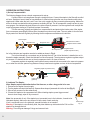
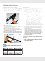
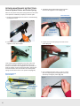
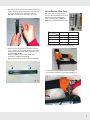
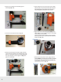
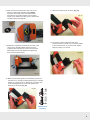
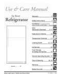
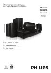
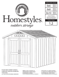
Safety, Operation & Maintenance Instructions
Long & Short Nose Upholstery Air Stapler (NSG10 & NS11)
IMPORTANT:
Drop 3 drops of oil into the stapler air inlet
BEFORE first use. See page 2.
Please read the safety, operation and maintenance
instructions BEFORE using the Air Stapler.
Upholstery Air Stapler (NSG10):
Air Exhaust
Trigger Safety
Safety Instructions:
1. Do not use oxygen, flammable gas, or any other type of gas as a
power source. Use regulated and filtered compressed air only.
2. Do not use gasoline or any other flammable liquid to clean the tool.
Trigger
Air Inlet
Magazine
Cover Latch
Fig. 1
IMPORTANT:
This manual contains safety warnings, operation, maintenance,
parts lists and diagrams. Keep the manual in a safe place for future
reference. The instructions will help you maximize the service life of
your stapler.
Nose (Staple Discharge Area)
Short Nose Upholstery Air Stapler (NS11):
3. Do not exceed the maximum operation air pressure of 100 psi.
4. Always disconnect the tool from the air supply before loading
staples, clearing a jam or servicing.
5. Always disconnect the tool from the air supply when not in
operation. Never leave tool unattended while connected to air
supply.
6. Do not carry tool by hose or move tool by pulling hose. Keep
hose away from heat, oil, solvents and any sharp edges. Replace
any damaged, weak or worn hoses.
7. Do not use tool as a hammer. Do not drop, drag or throw tool. If
tool is dropped, discontinue use and carefully examine for any bent,
cracked or broken parts. Listen for air leaks. Do not use tool until the
damage is repaired.
8. Always wear safety glasses and ear protection when using tool.
Fig. 2
SPECIFICATIONS:
- Operating air pressure range: 70 ~ 100 psi.
- Fastener type: 22 gauge fine wire 71 series staples.
- Fastener leg length range: ¼" to ⅝"
- NSG10 and NS11 staplers use the same fasteners
Rowley Company sells (SKU# NS32/E, NS33/E,
NS34/E, NS35/E).
- House fitting: ¼" NPT Milton
- Magazine capacity: 160 staples
APPLICATIONS:
- For upholstery: cornice boards, head boards, sofas,
chairs, ottomans, upholstered walls, etc.
- For Window treatment: covering dust boards,
mounting soft treatments to dust boards, etc.
9. When connecting tool to air supply, only use a coupling that will
release all air pressure from the tool when disconnected.
10. Do not point the tool at yourself or at any person. Always
assume that the tool is loaded and powered. Never engage in
horseplay.
11. Keep hands, or any body parts away from the stapler nose area
when the tool is connected to the compressed air.
12. Do not drive a staple on top of another staple.
13. Turn the trigger safety so the stapler will not fire accidentally
when connecting or disconnecting tool to compressed air.
14. Always keep firm footing when using tool.
15. Do not modify or disable trigger safety.
16. Do not modify any part of tool.
17. Keep tool out of reach of children.
1
OPERATION INSTRUCTIONS:
1) Set up Compressed Air:
The following diagram shows a simple compressed air set-up.
Connect a filter to air compressor through a straight air hose. Connect the stapler to the filter with a coiled
air hose. Straight air hose is ideal for long distances. A coiled air hose gives the user more freedom while using
stapler and is safer when the tool is not in use. Use quick couplers for easy connecting/disconnecting. Make sure
all the air hoses are rated with working pressure exceeding 200 psi. The air compressor usually has two air pressure gauges: One indicates the tank pressure; the other output air pressure. Use the regulator knob to adjust the
output air pressure starting at 70 psi and increase if necessary.
The filter removes moisture and debris from compressed air and protects the interior parts of the stapler
from unnecessary wear (Fig 3). Without filter, the stapler may shoot rusty water. The rusty water is from the tank.
Empty water from the tank regularly by following the air compressor manufacturer's instruction.
Fig. 3
Quick Coupler
Coiled Air Hose
Tank Pressure Indicator
Straight Air Hose
Tank
Filter
Air Compressor
Output Pressue Indicator
Regulator Knob
(adjust air pressure here)
An in-line lubricator and regulator can also be added as shown in Fig. 4.
The in-line lubricator is a convenient way to lubricate the tool. If an in-line lubricator is installed, do not lubricate the stapler manually. Check the lubricator's oil level frequently. The air pressure regulator regulates output
air pressure. It is better than the one on the air compressor since it is closer to the tool.
A separate regulator is especially useful when there are several tools connected to the same air compressor, or when the air hose spans a long distance. Always install an air regulator as close to the tool as possible.
Regulator (adjust air pressure here)
In-line Lubricator
(optional)
Filter
Fig. 4
OIL
2) Lubricate The Stapler:
Note: Stapler requires lubrication before first time use, or after a long period of no use. OIL
1. Disconnect the stapler from air supply.
2. Turn the stapler so that air inlet faces up. Squeeze three drops of pneumatic oil into the air inlet (Fig. 5).
3. Wipe off any excess oil at the exhaust cap.
4. Connect the stapler to the compressed air. Without loading staples, press trigger several
times to shoot empty, wipe off any excess oil.
Note: Use pneumatic oil only. If the stapler is not connected to an in-line lubricator, it needs to be
lubricated regularly. Add one or two drops of oil at the start of each work day.
If tool is connected to an in-line lubricator, manual lubrication is not needed.
Warning: If the stapler is not sufficiently oiled, the piston blade may stick and misfire. Fail to oil the
stapler may damage the tool.
Warning: Over oiling can damage O-rings and cause air leak.
2
OIL
Exhaust Cap
Fig. 5
OPERATION INSTRUCTIONS (cont.):
3) Make Sure All the Screws Are Tight:
Make sure the screw holding the L bracket (Fig. 6) is
tight. If not, tighten it. If the screw is missing, it may
be found at a home center. Its size is a M4x0.7x6
metric screw.
Fig. 6
4) Load Staples (Fig. 7):
1. We strongly suggest using staples from Rowley
Company. See size chart below.
2. Make sure tool is not connected to air supply.
3. Turn tool upside down. Depress the magazine latch,
and magazine cover will slide open.
4. Drop in a strip of staples with staple legs pointing up.
5. Push the magazine cover forward until latch catches.
Insert staples
(legs up)
Fig. 7
5) Shoot Staples:
Caution: Always wear safety glasses and ear plugs.
1. Connect the stapler to the air supply.
2. Regulate air pressure starting at 70 psi.
3. Rotate trigger safety to the side. Test stapling action
by driving a few staples into a piece of wood.
Note: Do not press the stapler firmly against the
stapling surface to fire staples. The compressed
air is sufficient to drive the staples in. Just lightly
rest the stapler nose against the stapling surface
and press the trigger. Pressing stapler firmly
against the surface will cause the staples to
penetrate too deep, cut fabrics and could
damage both stapling surface and stapler
piston. Apply slightly more pressure only when
stapling through very thick layers of fabrics to wood.
4. If staples are still driven too deep, first try to tilt the
stapler slightly, so stapler nose is at an angle from
the stapling surface.
5. If staples do not penetrate sufficiently, especially
when stapling into hardwood or if stapler misfires
occasionally, or the piston does not return to full up
position at the end of cycle, the air pressure may be
too low. Adjust regulator to increase air pressure
gradually and try again.
Warning: Do not exceed maximum operating pressure
of 100 psi.
6. After use, always disconnect stapler from air supply
and unload the staples.
Press latch
to open cover
Staples:
The following Rowley Company staples fit both NSG10
and NS11.
Stock #
NS32/E
NS33/E
NS34/E
NS35/E
Leg Length
6mm
10mm
13mm
16mm
Approx. Leg Length
1/4"
3/8"
1/2"
5/8"
3
TROUBLESHOOTING:
Problem:
Possible Cause:
Corrective Action:
1) Trigger can not be
depressed.
Trigger safety is in the way.
Turn the trigger safety to the side.
2) Stapler fires but does
not shoot staples.
2. Air pressure is too low.
Warning: Do not remove or tamper with the trigger safety. It is there to
prevent accidental firing.
Make sure staples are loaded correctly in the stapler (Fig. 7).
Adjust the regulator to increase output air pressure.
The optimum air pressure range for each stapler may vary. It also depends on the type of wood one is stapling into.
Warning: Do not exceed maximum operating pressure of 105 psi.
Note: Most air compressors have two gauges: one gauge displays
the tank pressure and the other indicates the stepped down output air
pressure. After turning on the air compressor, wait until the air compressor cuts off and the tank gauge stabilizes, then adjust the regulator. Set
initial air pressure to 70 psi and increase by 5 lb. increments until correct
pressure is achieved.
Caution: A faulty gauge or regulator may give incorrect pressure reading.
The only way to test this is to replace the gauge and/or the regulator.
3. Worn or cracked washer.
Open the stapler magazine cover, remove the staples and shoot the
stapler several times while the magazine cover is open. If the piston
blade does not retract fully (totally disappears into the stapler body) at the
end of the cycle, it is very likely that the washer is worn and need to be
replaced. See How to Replace Washer or call Rowley Company.
4. Stapler has an air leak.
Listen carefully for any air leak from the stapler. If air leak is detected from
air inlet plug, unscrew the inlet plug, wrap a strip of Teflon® sealing tape
around the threads, screw in the inlet plug. If air leaks from other parts of
the stapler, call Rowley Company for further information.
Note: A burst of air follows each shooting cycle. This is normal.
4
5. Damaged piston.
A damaged piston blade often damages the bumper.
Replace both (See How to Replace Piston and
Bumper), or call Rowley Company.
3) Stapler does not fully
drive staples.
1. Air pressure is too low.
See corrective action for problem (2).
4) Piston blade appears
stuck, or sticking out of
the nose when not shooting, or stapler cycles
sluggishly.
1. Stapler does not have
adequate lubrication.
Add 2 drops of pneumatic lubricating oil through the stapler air inlet, or
install an in line lubricator and make sure the oil level in the lubricator is
adequate.
Note: Add one to two drops of oil at the start of each work day.
5) Stapler drives the
staples too deep and/
or damages the stapling
surface or cuts fabric or
make the fabric appear
buckled.
1. Operator presses the
stapler too firmly against the
stapling surface.
Unlike an electrical stapler, one does not need to and should not hold the
stapler firmly against the stapling surface. Rest the stapler nose lightly on
the stapling surface, then press the trigger. If the staples are still too deep,
tilt the stapler slightly, so stapler nose is at an angle from the stapling
surface.
Caution: Pressing hard on the stapler will not only damage the stapling
surface but could also damage the stapler piston and shorten the stapler
life.
TROUBLESHOOTING (Cont.):
Problem:
Possible Cause:
Corrective Action:
6) Stapler intermittently
misfires staples
1. Worn washer
See corrective action for problem (2).
2. Incorrect staples.
Check the staples, make sure the correct staple type is loaded in the
stapler.
3. Debris in magazine chamber prevents pusher from
pushing staples forward
smoothly.
Slide the magazine cover off the stapler (See Step 1 &
2 in How to Replace Pusher and Pusher Spring).
With a soft cloth or air gun, clean the pusher, magazine chamber and the
magazine cover.
4. Worn pusher and/or push- See How to Replace Push and Pusher Spring. Or call Rowley
er spring.
Company.
7) Staples appear stuck.
Staples are not feeding
properly
5. Low air pressure
See corrective action for problem (2).
1. Incorrect staples.
See corrective action for problem (6).
2. Debris in magazine
chamber.
See corrective action for problem (6).
3. Worn pusher and/or push- See corrective action for problem (6).
er spring.
8) Stapler is jamming
1. Incorrect staples.
See corrective action for problem (6).
2. Debris in magazine
chamber.
See corrective action for problem (6).
3. Shooting one staple on
top of another staple
Do not shoot one staple over other staples.
4. Worn pusher and/or push- See corrective action for problem (6).
er spring.
5. Staples jam in the nose
tip.
9) Stapler has an air leak
The driver guide (part # 32) is bent or the latch spring (part # 39) is too
loose. Call Rowley Company.
See corrective action for problem (4).
10) Stapler spits water
and/or rust
1. Air compressor tank has
condensation water and/or
is rusted.
Empty out the air compressor tank and purge the air supply line according
to the manufacturer’s instruction. Add a filter to the compressed air line
(Fig. 3).
11) Stapler magazine cover slides off the stapler.
Pusher and pusher spring
falls out.
1. The screw holding the L
bracket is loose and falls off.
See How to Replace Pusher and Pusher Spring. Or call Rowley Co.
To prevent this problem from happening again, check the screw (Fig. 6,
page 3) before use and make sure the screw is tight.
5
REPAIR & MAINTENANCE INSTRUCTIONS:
How to Replace Pusher and Pusher Spring
3. Thread the spring behind and around the tension
roller into the magazine cover slot (Fig. 11).
With use, the pusher and pusher spring will be worn and need
to be replaced. Call Rowley Company to order the parts.
1. Undo the screw (Fig. 8) and remove the L bracket holding
the magazine cover.
Fig. 8
This end will be connected to
magazine cover slot hook in
Step 6.
This end will be
connected to the
pusher in Step 4.
Thread spring
around the
tension roller
Fig. 11
4. Connect one end of the spring to the hook on the
pusher (Fig. 12).
2. Press the magazine latch (Fig. 9) to slide the
magazine cover off the stapler.
Fig. 9
Look closely inside the magazine cover slot, at the nose
end, there is a tension roller for the pusher spring to go
around. In the bottom of the magazine cover slot there is a
hook for hooking one end of the pusher spring. Spring goes
around the tension roller and the other end of the pusher
spring connects to the hook on the pusher. See (Fig. 10).
Spring Go Around
Tension Roller
Pusher
Pusher Spring
Connect one
end of spring to
the Magazine
Cover Hook
Pusher Hook
Fig. 10
6
5. Use a straightened paper clip or a T-pin to pull the
other end of spring out of the magazine cover slot,
while firmly holding the pusher (Fig. 13).
Fig. 13
Magazine Cover
Connect the other
end to Pusher
Hook
Fig. 12
6. Hold the pusher firmly in one hand, with the other hand,
slightly stretch the spring, bend slightly, and hook the
spring onto the hook in the magazine cover slot
(Fig. 14). be careful not to over stretch the spring.
Fig. 14
How to Replace Other Parts
With use, some parts may break or
wear out. See the table below for stock
numbers of most replacable parts.
Order Lubricant Syringe (AS65) also.
AS65 will be used in the following steps.
Piston
Bumper
Stapler
Washers
NSG10
NS11
Piston
NSG10/P15
NS11/P13
Bumper
NSG10/P16
NS11/P14
Washer
NSG10/P19
NS11/P17
Metal Washer
NSG10/P20
no metal washer
Parts
1. Unscrew the three bolts as shown in Fig. 16.
7. Now one end of the spring is connected to the hook
in the magazine cover slot (Fig. 15-(1)) and the other
end goes around the tension roller and hooked on to
the pusher (Fig. 15-(2)).
Slide the magazine cover on the stapler while
pressing the magazine latch (Fig. 9)
Replace the bracket and fasten in the screw (Fig. 8).
(2)
Fig. 16
(1)
To remove the screw at the back end of the stapler,
use a wrench to keep the nut from spinning (Fig. 17).
Fig. 17
Fig. 15
7
2. Remove the magazine/nose assembly (1) and
washers (2) (Fig. 18).
Fig. 18
5. Pull the piston (1) out. A pair of pliers can be helpful.
Wrap the jaws of a pair of pliers with fabrics and pull
the cylinder (2) out with a slight twist. Remove the
old bumper (3) from the bottom of the cylinder.
(2)
(1)
(1)
(2)
(3)
Fig. 21
3. Unscrew the four bolts as shown in Fig. 19.
Fig. 19
6. Apply small mount of lubricant grease (AS65) to the
outer surface of a new bumper. Place the new bumper
into the bottom of the cylinder.
Insert the cylinder into the stapler. Push the cylinder
down and make sure it is all the way down inside the
stapler body (Fig. 22).
Grease here
4. Remove the bolts (1) and exhaust cap (2). Carefully
remove the entire cylinder cover assembly (3), so the
parts do not fall apart. Remove the sealing gasket (4).
If the parts fall apart, see the diagram in Step 10 on
page 9 to reassemble.
(1)
(2)
(4)
(3)
7. Make sure the new piston is clean. Apply lubricant
grease (AS65) to the disk part of the piston, especially
around the O-ring. Insert the piston, and make sure
that the blade is oriented in the correct direction (As
indicated by the arrow in Fig. 23).
Grease here
Fig. 20
8
Fig. 22
Fig. 23
11. Place the exhaust cap on as shown (Fig. 27).
8. Make sure the new washers are clean, free of any
debris or cracks. Apply lubricant grease (AS65)
around the outer edge of the new rubber washer.
First place the new rubber washer, then the metal
washer on the stapler and make sure the washers are
oriented properly (See Fig. 24).
Fig. 27
Grease
Fig. 24
12. Insert the four bolts. Tighten the bolts while
pressing down the exhaust cap. Connect the stapler
to the compressed air. Try to shoot a few staples.
Make sure there is no air leak.
9. Replace the magazine/nose assembly as shown. Take
care to line up the piston blade with the slot in the
magazine/nose assembly. Be careful not to bend the
piston blade. Do not force! Replace and tighten the
three screws as shown below.
Fig. 28
Fig. 25
10. Make sure the entire cylinder cover assembly is intact, all
the parts are on, including compressed spring (3), rectangle
washer (4), cylinder cover (5), O-Rings (6 & 7), piston stop
(8) and sealing gasket (17). Place the cylinder cover
assembly on as shown (Fig. 26).
Fig. 26
3
4
5
6
7
8
16
Cylinder Cover
Assembly
9
Limited Warranty
•
Limited Warranty
The warranty covers material and workmanship
• After warranty period expires, customers can still
defects
of the Long
and
Short and
Nose
Upholstery defects
- The warranty
covers
material
workmanship
Stapler
NSG11)
by Rowley
Co.
of the (NSG10
Long and&Short
Nosesold
Upholstery
Stapler
• The(NSG10
warranty
period
is
90
days
from
the
date
& NS11) sold by Rowley Company. of
purchase.
- The warranty period is 90 days from the date of
purchase.
• During
the warranty period, replacements or repairs (at
- During
the warranty
period,
replacements
repairs
Rowley
Co.’s
discretion)
of the
tool will be or
made
free(at
Rowley Company’s discretion) of the tool will be made
of charge.
of charge.
• Thefree
warranty
does not cover damages by accident,
The
notstaples
cover damages
by accident,by
misusewarranty
or due todoes
using
not recommended
misuse
or due
to using staples
bythe
Rowley
Co.
Unauthorized
repairnot
or recommended
modification of
Rowley Company. Unauthorized repair or modification
tool will void the warranty.
receive
repair
services
from
Rowley can
Co. still
The
- After
warranty
period
expires,
customers
customer
be charged
the labor
and parts
receive
repairwill
services
from Rowley
Company.
The cost.
•customer
To receive
thecharged
repairs the
or replacements
will be
labor and partsunder
cost.
- To warranty
receive the
or replacements
under
orrepairs
to obtain
repair services
after warranty
warranty
to obtain
repair
warranty
periodor
expires,
the
tool services
must beafter
returned
to Rowley
period
the tool must
be returned to Rowley
Co. expires,
at the customer’s
expense.
at of
thethe
customer’s
expense.
•Company
The user
tool must
read and understand the
- The
user
of
the
tool
must
read
and understand
safety, operation and instructions.
Rowleythe
Co. is not
safety,
operation
and
instructions.
Rowley
liable for any personal injuries or material damages
Company
is notdirectly
liable for
personal
injuries
associated
or any
indirectly
with
usingorthis tool.
material damages associated directly or indirectly
with using this tool.
of the tool will void the warranty.
Parts Diagram & List for NSG10:
PARTS DIAGRAM & LIST FOR NSG10:
32
46
20
#
1
2
3
4
5
6
7
8
9
10
Part Name
Bolt M5X50
Exhaust Cap
Compression Spring
Rectangle Washer
Cylinder Cover
O-Ring 11.7X2.4
O-Ring 26.2X2.4
Piston Stop
Bumper Washer
O-Ring 21.3X3
#
11
12
13
14
15
16
17
18
19
20
Part Name
O-Ring 29.2X3.55
O-Ring 20.3X3
Cylinder
O-Ring 2.65X18
Piston Assembly
Bumper
Sealing Gasket
Gun Body
Rubber Washer
Metal Washer
#
21
22
23
24
25
26
27
28
29
30
Part Name
Rectangle Washer
Trigger Valve Seat
Valve Stem Spring
Trigger Valve Stem
O-Ring 5X1.5
Trigger Valve Guide
O-Ring 11.2X2
Trigger Safety
Compression Spring
Step Pin
#
31
32
33
34
35
36
37
38
39
40
Part Name
Trigger Lever
O-Ring 1.7X2
Bolt M5X20
Spring Washer 5
Driver Guide
Spacer
Fixed Magazine
L-Bracket
Bolt M4X6
Bolt M4X16
#
41
42
43
44
45
46
47
48
49
50
Part Name
Movable Magazine
Pusher
Tension Roller
Roller Pin
Pusher Spring
Step Pin
Latch
Latch Spring
Support
Spring Washer 4
#
51
52
53
54
55
56
Part Name
Self-lock Nut M5
Rubber Handle Sleeve
O-Ring 35.5X2.3
End Cap
Air Inlet Plug
Air Inlet Cover
-10-
10
PARTS DIAGRAM & LIST FOR NS11:
Parts Diagram & List for NS11:
#
1
2
3
4
5
6
7
8
9
Part Name
Bolt M5X20
Exhaust Cap
Compression Spring
Rectangle Washer
Cylinder Cover
O-Ring 11.7X2.1
O-Ring 16.2X2.1
Piston Stop
Collar
#
10
11
12
13
14
15
16
17
18
Part Name
O-Ring 2.65X30.2
Cylinder
O-Ring 2.65X18
Piston
Bumper
Sealing Gasket
Gun Body
Washer
Rectangle Washer
#
19
20
21
22
23
24
25
26
27
Part Name
Trigger Valve Seat
Trigger Valve Stem
O-Ring 1.7X2
Trigger Valve Guide
O-Ring 11.2X2
Trigger Safety
Compression Spring
Step Pin
Trigger Lever
#
29
30
31
32
33
34
35
36
37
Part Name
C-Clip 2.5
Bolts M5x20
Spring Washer 5
Driver Guide
Spacer
Fixed Magazine
L Bracket
Bolt M4X6
Spring Washer 4
#
38
39
40
41
42
43
44
45
46
Part Name
Support
Latch Spring
Latch
Step Pin
Pin M2X10
Bolt M4X12
Pin M2X8
Movable Magazine
Pusher
#
47
48
49
50
51
52
53
54
Part Name
Tension Roller
Roller Pin
Pusher Spring
Nut M5
Rubber Handle Sleeve
O-Ring 35.5X2.3
End Cap
Air Inlet Plug
11
-12-