1
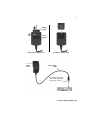
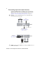
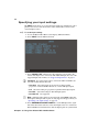
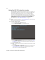
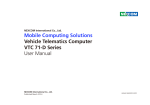
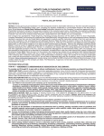
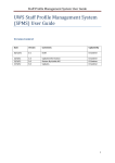
Matrox MC-100
User Guide
August 11, 2014
Y11196-301-0130
Contents
Chapter 1
Introduction
Welcome to Matrox MC-100 ................................................................ 2
Matrox MC-100 requirements..................................................................... 2
Updating your MC-100 hardware ......................................................... 2
Last-minute information ....................................................................... 3
Chapter 2
Connecting External Devices to Matrox MC-100
Available Matrox MC-100 connections................................................. 6
Powering Matrox MC-100..................................................................... 6
Matrox MC-100 operating safety feature .................................................... 6
Matrox MC-100 power supply and adapter plugs....................................... 6
Connecting input and output devices................................................... 8
Chapter 3
Using Your Matrox MC-100 Hardware
Overview.............................................................................................. 10
Understanding the MC-100 status LEDs ............................................. 10
Using the MC-100 DIP switches .......................................................... 10
MC-100 channel definitions ..................................................................11
Amplifying input signals ....................................................................... 12
Time base correction and synchronization ......................................... 12
Loss-of-signal switcher ....................................................................... 12
How it works ............................................................................................. 12
Enabling the loss-of-signal switcher .......................................................... 13
Using the OSD buttons ........................................................................ 14
Accessing the OSD main menu ........................................................... 14
Specifying your input settings ............................................................. 16
Viewing input information .......................................................................... 17
Supported input formats............................................................................ 17
Specifying your output settings ........................................................... 18
Specifying your 3D settings ................................................................ 20
Using the MC-100 selection modes ................................................... 22
vi
Saving option settings.........................................................................24
Resetting the DIP switches to factory defaults ..........................................24
Appendix A
Matrox MC-100 Supported Output Formats
Supported output formats when using input SDI 1 only ......................26
Supported output formats when using input SDI 2 only......................28
Supported output formats when using inputs SDI 1 and SDI 2 ...........30
Appendix B
Matrox MC-100 Specifications
Matrox MC-100 specifications ............................................................34
General .....................................................................................................34
Environmental specifications .....................................................................35
Appendix C
Matrox Customer Support
How to get Matrox customer support ................................................38
Registration ...............................................................................................38
Keep up to date with our website .............................................................38
Contacting us ............................................................................................38
Index .......................................................................................... 39
Contents
1
Introduction
This chapter lists the Matrox
MC-100 requirements, and
explains how to update the
MC-100 hardware.
2
Welcome to Matrox MC-100
Matrox MC-100 is a dual SDI to HDMI mini converter that supports a wide
range of display resolutions through 3G, dual link, HD, and SD-SDI. The Matrox
MC-100 unit can be used as an HD-SDI switcher, a distribution amplifier, a
multiplexer, and a 3D processing unit. The Matrox MC-100 is configured using
an on-screen display (OSD) that is accessed by three buttons directly on the unit.
The Matrox MC-100 unit has predefined and user-defined DIP switches. In
addition, you can update MC-100’s firmware using a Mini USB cable.
Matrox MC-100 requirements
MC-100 is designed to work independently of a computer. However, you will
require the following:
• At least one SDI or HDMI display device for specifying the MC-100
settings.
• If using an HDMI display device, a good-quality HDMI cable for connecting
the HDMI display device to the HDMI output connector on the Matrox
MC-100 unit.
²Caution Using a low-quality HDMI cable can damage the HDMI connector
on the Matrox MC-100 unit.
• To perform the hardware update, you will require a computer with the
following:
$
Microsoft Windows 7 (32-bit and 64-bit) with Service Pack 1, or
Microsoft Windows XP (32-bit) with Service Pack 3.
$
A USB port and a third-party USB cable to connect Matrox MC-100 to
your computer. If your computer does not have a USB port, or if it has a
different type of USB port, you can use a compatible USB adapter/cable.
Updating your MC-100 hardware
Matrox MC-100 has a Mini USB Type B port that is used for updating the
hardware’s firmware and FPGA. In order to perform a hardware update for
MC-100, you must download and run the latest version of the Matrox MC
Updater on a Windows system. A third-party USB cable is also required for the
hardware update. To see if a new hardware update is available for your MC-100,
visit the Downloads section of our website at www.matrox.com/video/support.
¦ Note Although MC-100 is designed to work independently of a computer, you
must download and run the updater on a Windows system. The Matrox MC
Updater does not support Mac OS systems.
Chapter 1, Introduction
3
° To update the MC-100 hardware:
1 Download the latest version of the Matrox MC Updater on a Windows
system.
¦ Note To revert to the previous version of the MC-100 hardware, you can
download and run the older version of the Matrox MC Updater.
2 Disconnect all SDI and HDMI cables from MC-100.
3 Power your MC-100 (see “Powering Matrox MC-100” on page 6), and then
connect a third-party USB cable from MC-100’s USB port to your
computer’s USB port.
¦ Note If your computer does not have a USB port, or if it has a different type
of USB port, you can use a compatible USB adapter/cable.
4 Run the Matrox MC Updater.
5 If an update is required for your MC-100 firmware and/or FPGA, the
Update button will be active in the Matrox MC Updater window. If the
MC-100 hardware is up to date, but you wish to force a hardware update,
select Force update. Click Update to begin the MC-100 update.
¡ Important To avoid damaging the MC-100 hardware, do not turn off your
computer, remove power from MC-100, or disconnect it from your computer
during the hardware update.
6 When prompted by the updater, disconnect and then reconnect the MC-100
power supply cable to complete the firmware update.
Last-minute information
Any important information that wasn’t available for inclusion in this manual by
publication time is provided to you in the Matrox MC-100 Release Notes.
Last-minute information
2
Connecting External Devices to
Matrox MC-100
This chapter shows how to
supply power and connect
external devices to
Matrox MC-100.
6
Available Matrox MC-100 connections
Matrox MC-100 provides the following inputs and outputs for connecting
external devices:
• Two BNC SDI input connectors, and two BNC SDI output connectors, with
up to 16 channels of embedded audio per connector.
• One HDMI output connector with up to eight channels of embedded audio.
Powering Matrox MC-100
You can supply power to Matrox MC-100 using an AC outlet via the Matrox
external power supply cable. To turn MC-100 off, unplug the Matrox external
power supply cable from the AC outlet.
¦ Note For a secure power connection, use the locking connector supplied on the
power supply cable to fasten it to MC-100.
Matrox MC-100 operating safety feature
Matrox MC-100 has an operating safety feature that will cause all four SDI LEDs
to flash red as a warning when the MC-100 unit exceeds normal operating
temperature. If all four SDI LEDs flash red, unplug the external power supply
cable from the AC outlet, and wait a few minutes for the MC-100 unit to cool
before reconnecting the power supply cable back into the AC outlet.
Matrox MC-100 power supply and adapter
plugs
Matrox MC-100 provides an external power supply cable with international
adapter plugs for use in different regions:
• To remove an adapter plug from the power adapter, hold down the button on
the adapter plug, and then slide the adapter plug up until it releases from the
power adapter.
• To insert an adapter plug into the power adapter, ensure that the adapter plug
is properly aligned with the corresponding slot on the power adapter, and
then slide the adapter plug down into the power adapter until it locks into
place.
Chapter 2, Connecting External Devices to Matrox MC-100
7
1
Adapter
plug
0
Power
adapter
Removing an adapter plug
To AC
outlet
Inserting an adapter plug
Power supply
cable
Fasten the power supply
cable to MC-100 using
the locking connector.
MC-100
Powering Matrox MC-100
8
Connecting input and output devices
The Matrox MC-100 unit supports two SDI input sources via two BNC input
connectors, two SDI output devices via two BNC output connectors, and one
HDMI output device. For a list of the supported input and output formats, see
Appendix A, “Matrox MC-100 Supported Output Formats,” on page 25.
¡ Important If you’re connecting two input sources to MC-100, the input
sources must be the same video format.
To SDI input
sources
Power
(see “Powering Matrox
MC-100” on page 6)
MC-100
Infrared sensor (not used)
Mini USB Type B port
(see “Updating your MC-100
hardware” on page 2)
OSD buttons
(see “Using the OSD
buttons” on page 14)
MC-100
To HDMI
output device
To SDI output
devices
²Caution Using a low-quality HDMI cable can damage the HDMI connector on
the Matrox MC-100 unit.
Chapter 2, Connecting External Devices to Matrox MC-100
3
Using Your Matrox MC-100 Hardware
This chapter explains how to
use your Matrox MC-100
hardware.
10
Overview
Matrox MC-100 is operated through an on-screen display (OSD) using the OSD
buttons, which are located on the MC-100 unit. MC-100 also features status
LEDs (see “Understanding the MC-100 status LEDs”), and eight DIP switches
for performing various functions (see “Using the MC-100 DIP switches”).
Understanding the MC-100 status LEDs
Matrox MC-100 features the following status LEDs:
• SDI 1 and SDI 2
$
Green
$
Red
An input source is detected.
An input source is not connected.
• SDI 3 and SDI 4
$
Green
$
Red
The output is supported.
The output is not supported.
• Power The LED is green when power is supplied to MC-100 and the
hardware is functioning properly.
¦ Note If the MC-100 unit exceeds normal operating temperature, all four SDI
LEDs will flash red as a warning. For more information see “Matrox MC-100
operating safety feature” on page 6.
Using the MC-100 DIP switches
Matrox MC-100 features eight DIP switches on the side of the unit for
locking/unlocking the on-screen display (OSD) buttons, displaying the OSD or
heads-up display (HUD) on the SDI or HDMI output, enabling/disabling the
Chapter 3, Using Your Matrox MC-100 Hardware
11
loss-of-signal switcher feature, and loading user-defined settings. A DIP switch
is ON when the switch is down, and OFF when it is up.
O
O
M
• DIP switch 1
When ON, the OSD buttons are locked and will not function.
• DIP switch 2
outputs.
When ON, the OSD or HUD is displayed on the SDI
• DIP switch 3
output.
When ON, the OSD or HUD is not displayed on the HDMI
• DIP switch 4 When ON, the loss-of-signal switcher feature is enabled (see
“Loss-of-signal switcher” on page 12”).
• DIP switches 5 to 8 Used for loading user-defined presets of input, output,
and 3D settings. For information on how to save user-defined presets, see
“Saving option settings” on page 24.
¦ Note MC-100 can have only one user-defined preset loaded at any given
time. This means that if a DIP switch associated with a user-defined preset is
ON, you must turn it OFF before loading another preset.
MC-100 channel definitions
Matrox MC-100 can process up to two video channels at one time. Use the
following channel definitions when specifying the output settings:
• For all input video signals except 3G level B, channel 1 refers to the input
signal on SDI 1, and channel 2 refers to the input signal on SDI 2.
• If one 3G level B input video signal is connected to MC-100, channel 1 and
channel 2 refer to the two channels in the 3G level B signal. If you connect
two 3G level B input signals, channel 1 and channel 2 refer to the two
channels in input SDI 1, and the 3G level B signal connected to SDI 2 can be
MC-100 channel definitions
12
output using the SDI 2 bypass option only (see “Specifying your output
settings” on page 18).
• When you select the Channel 1, Channel 2, 3D, Analysis, or Multiplex
option for a given output (see “Specifying your output settings” on page 18),
channel 1 and/or channel 2 is output using the current MC-100 settings. If
you want to output an input video signal without applying the MC-100
settings, choose the SDI 1 bypass or SDI 2 bypass output option instead.
Amplifying input signals
MC-100 also functions as an input signal amplifier. Input signals connected to
MC-100 are automatically amplified within MC-100. This allows you to transfer
the SDI and HDMI output signals over greater distances. The distances for the
different input types are as follows:
• SD
300 meters (984 feet)
• HD
100 meters (328 feet)
• 3G
70 meters (229 feet)
Time base correction and synchronization
When input sources are connected to SDI 1 and SDI 2, MC-100’s time base
corrector ensures that the two video signals are synchronized at the output by
using the video signal that is set as the reference source (see “Specifying your
input settings” on page 16) to correct the other video signal. MC-100’s time base
does not correct the audio portion of the signal.
¦ Note The time base corrector does not apply when using the SDI 1 bypass or
SDI 2 bypass output setting (see “Specifying your output settings” on page 18).
This means that if the two input sources are not synchronized using an external
reference source, the input signals may not be synchronized at the output.
Depending on the amount of discrepancy between the two input signal clocks,
the input signal that is not set as the reference source may not be output.
Loss-of-signal switcher
The loss-of-signal switcher feature enables MC-100 to automatically switch to a
different channel if it detects a signal loss on a main channel. This feature is
supported on the SDI 4 output only.
How it works
Let’s say you have a primary and an offline HD-SDI video signal connected to
SDI 1 and SDI 2 respectively. You then set SDI 3, SDI 4, and the HDMI output
(optional) to Channel 1 in the settings menu.
Chapter 3, Using Your Matrox MC-100 Hardware
13
In the event of a signal loss on the SDI 1 input, the MC-100 will automatically
switch to the input on SDI 2 to output a video signal on SDI 4. The SDI 3 and
HDMI outputs will display a purple screen as long as the signal on SDI 1 remains
invalid. This indicates that there is no valid input on SDI 1. When a valid primary
signal is again detected on SDI 1, SDI 4 will automatically switch back to display
the signal from SDI 1. The MC-100 must detect nothing but a clean valid video
signal during the delay or it will not switch. The SDI 3 and HDMI outputs will
also return, and display the signal from SDI 1 once the clean signal is detected.
Remarks
• To avoid glitches when switching channels, you must set the reference
source priority to the channel you want to use as the backup, and it is
recommended to use SDI 2 as the backup channel. As long as the backup
channel stays valid for the entire operation, the loss and return of channel 1
should result in a clean, glitch-free switch. For more information on setting
the reference source priority, see “Specifying your input settings” on
page 16.
• A switch is triggered when the MC-100 detects an invalid SDI signal of
approximately one frame or longer in duration. A loss of video content, such
as a black or blank signal, will not trigger a switch.
• You must use the same video format on both inputs.
• This feature is not available when you have NTSC or PAL as the input video
format.
• While the initial switch from the primary to the backup input is done as soon
as a fault is detected in the signal, the automatic return does not occur
instantly. The MC-100 must detect a few seconds of valid video before a
return will occur. The delay depends on the resolution and frame rate of the
signal input.
• You must define specific input channels to output channels in the output
menu. The switching functionality does not work in Bypass mode.
Enabling the loss-of-signal switcher
You enable the loss-of-signal switcher by configuring settings in the OSD main
menu, and by using the OSD buttons.
1 Access the Matrox MC-100 on-screen display (OSD) main menu.
For more information, see “Accessing the OSD main menu” on page 14.
2 From the input settings, set your REFERENCE SOURCE PRIORITY to the
SDI input you want as the backup (SDI 2 is recommended).
For more information, see “Specifying your input settings” on page 16.
3 From the output settings, set SDI 3, SDI 4, and the HDMI output (optional)
to Channel 1.
Loss-of-signal switcher
14
4 On the MC-100, turn on DIP switch 4 (turn the switch down) to enable the
loss-of-signal switcher.
For more information, see “Using the MC-100 DIP switches” on page 10.
The loss-of-switcher feature is enabled, and will trigger a switch to the backup
channel if a signal loss is detected on the main channel.
Using the OSD buttons
The on-screen display (OSD) buttons are used to navigate through the Matrox
MC-100 options in the OSD menu.
¦ Note You can lock the OSD buttons by using DIP switch 1 (see “Using the
MC-100 DIP switches” on page 10).
•
(Cycle buttons) Use these buttons to cycle through the OSD
+ and
menu options and settings, or available settings when in selection mode (see
“Using the MC-100 selection modes” on page 22).
•
(Select button) Use this button to select the highlighted OSD menu
option, currently selected option, or to exit selection mode (see “Using the
MC-100 selection modes” on page 22).
Accessing the OSD main menu
The Matrox MC-100 on-screen display (OSD) main menu is accessed using the
OSD buttons. The OSD main menu allows you to set the input, output, and 3D
settings, and allows you to access the various selection modes (see “Using the
MC-100 selection modes” on page 22).
° To access the Matrox MC-100 OSD main menu:
1 Make sure that power is supplied to Matrox MC-100 (see “Powering Matrox
MC-100” on page 6), and you have at least one SDI or HDMI output display
device connected to Matrox MC-100 (see “Connecting input and output
devices” on page 8).
¦ Note By default, the OSD will appear on the display device connected to
MC-100’s HDMI output only. To hide the OSD on the HDMI output, or to
display it on the SDI outputs, you must set the MC-100 DIP switches
accordingly (see “Using the MC-100 DIP switches” on page 10).
Chapter 3, Using Your Matrox MC-100 Hardware
15
2 Press any OSD button on the Matrox MC-100 unit. The Matrox MC-100
OSD main menu will appear on the display device connected to MC-100’s
SDI and/or HDMI output. Select EXIT to close the OSD.
Accessing the OSD main menu
16
Specifying your input settings
The INPUT menu allows you to select the input signal type and reference source
priority. You can also view the reference status, and the video formats for the
connected input sources.
° To set the input settings:
1 Access the Matrox MC-100 on-screen display (OSD) main menu.
2 Select INPUT from the OSD main menu.
3 Select SIGNAL TYPE, and then select the setting that corresponds to the
format of the input source connected to MC-100’s SDI input. For a list of the
supported input video formats, see “Supported input formats” on page 17.
¡ Important If you have input sources connected to SDI 1 and SDI 2, the
two video formats must be the same.
$
Standard Select this setting for progressive or interlaced SD,
progressive or interlaced HD, 3G level A, or 3G level B input signals.
$
PsF
$
Dual link
$
Dual link PsF
Select this setting for progressive segmented frame input signals.
Select this setting for dual link input signals.
Not supported.
¦ Note PsF input video signals are not supported on the HDMI output. For
SDI outputs, PsF input video signals are only supported in bypass mode (see
“Specifying your output settings” on page 18).
4 Select REFERENCE SOURCE PRIORITY to set the SDI input video signal
that will be used as the reference source when input sources are connected to
SDI 1 and SDI 2. For information on how the input signals are synchronized
Chapter 3, Using Your Matrox MC-100 Hardware
17
using MC-100’s time base corrector, see “Time base correction and
synchronization” on page 12. When only one input source is connected to
MC-100, this option does not apply, and the connected video signal is
automatically used as the reference source.
Sets the video signal connected to the SDI 1 input as the
reference.
$
SDI 1
$
SDI 2
Sets the video signal connected to the SDI 2 input as the
reference.
Viewing input information
The INPUT menu also allows you to view the following input information:
• REFERENCE STATUS Indicates whether or not the reference is locked to
the input source.
• CHANNEL 1 FORMAT and CHANNEL 2 FORMAT Indicates the video
format that is detected for channels 1 and 2. MC-100 cannot detect a PsF or
dual link video signal.
¦ Note For more information on the MC-100 channels, see “MC-100 channel
definitions” on page 11.
Supported input formats
MC-100 supports the following input video formats. To see the possible outputs
for the supported input formats, see Appendix A, “Matrox MC-100 Supported
Output Formats,” on page 25.
¦ Note 4:4:4 input video signals are not supported.
• NTSC
• PAL
• 1280×720p at 50, 59.94, and 60 fps
• 1920×1080i at 50, 59.94, and 60 fps
• 1920×1080PsF at 23.98, 24, 25, 29.97, and 30 fps
• 1920×1080p at 23.98, 24, 25, 29.97, and 30 fps
• 3G level A 1920×1080p at 50, 59.94, and 60 fps
• 3G level B 1920×1080p at 50, 59.94, and 60 fps
• Dual link 1920×1080p (4:2:2) at 50, 59.94, and 60 fps
Specifying your input settings
18
Specifying your output settings
The OUTPUT menu allows you to select the video signal for a given output
connector, as well as the HDMI audio channels. The output signal also includes
the ancilliary data contained in the input video signal. If you select 3D or
Analysis, the ancilliary data that is output is from channel 1 only.
° To set the output settings:
1 Access the Matrox MC-100 on-screen display (OSD) main menu.
2 Select OUTPUT from the OSD main menu.
3 For the SDI and HDMI outputs, select SDI 4, SDI 3, or HDMI, and then
select your desired output setting. For information on the MC-100 channels,
see “MC-100 channel definitions” on page 11.
Remarks
•
PsF input video signals are not supported on the HDMI output. For SDI
outputs, PsF input video signals are only supported in bypass mode.
•
You must have two input channels for the 3D, Analysis, and Multiplex
option settings to function properly.
•
3D and Analysis output settings are not supported for 3G level A input
signals.
•
Multiplex is not supported on the HDMI output or for 3G level A input
signals.
•
In order to view the selected video output format, the format must be
supported by your SDI or HDMI display device. If the format is not
supported, a purple screen is displayed and the OSD is available if the
Chapter 3, Using Your Matrox MC-100 Hardware
19
appropriate DIP switch for the OSD has been set (see “Using the
MC-100 DIP switches” on page 10).
Outputs the video signal connected to input SDI 1 as is,
without any processing. The MC-100 settings do not apply for this option.
$
SDI 1 bypass
$
SDI 2 bypass
$
Channel 1 Outputs the video signal on channel 1 using the current
MC-100 settings.
$
Channel 2 Outputs the video signal on channel 2 using the current
MC-100 settings.
$
3D Outputs the channel 1 and 2 input video signals as set in the 3D
MODE option in the 3D SETTINGS menu. The channel flip and channel
Outputs the video signal connected to input SDI 2 as is,
without any processing. The MC-100 settings do not apply for this option.
offset options are also applied to the output (see “Specifying your 3D
settings” on page 20).
$
Analysis Outputs the channel 1 and 2 input video signals as set in the
ANALYSIS MODE option in the 3D SETTINGS menu. The channel flip
and channel offset options are also applied to the output (see “Specifying
your 3D settings” on page 20).
$
Multiplex (SDI 4 and SDI 3 only) Combines the video and audio input
signals from channel 1 and channel 2 into one 3G level B video signal on
the output. The channel flip and channel offset options are also applied to
the output (see “Specifying your 3D settings” on page 20).
4 If you have an HDMI output device connected to MC-100, select
HDMI AUDIO CHANNELS, and then select the audio channels that you
want to output on HDMI. The source of the audio channels is defined by the
output setting selected in step 3.
¦ Note When using the 3D or Analysis output setting in step 3, or when using
a 3G level B input video signal, the HDMI audio channels are selected from
channel 1 only.
$
1-8
$
9-16
Outputs audio input channels 1 to 8.
Outputs audio input channels 9 to 16.
Specifying your output settings
20
Specifying your 3D settings
The 3D SETTINGS menu allows you to select the 3D viewing mode and
3D analysis mode for channels 1 and 2. It also allows you to flip the channel 1
and channel 2 video input signals horizontally or vertically, as well as apply a
vertical and horizontal offset to channels 1 and 2. See “MC-100 channel
definitions” on page 11 for information about the MC-100 channels.
° To set the 3D settings:
1 Access the Matrox MC-100 on-screen display (OSD) main menu.
2 Select 3D SETTINGS from the OSD main menu.
3 Select 3D MODE, and then select the 3D viewing mode for channels 1 and 2.
If your display device supports the selected 3D viewing mode option, then
the image is 3D. To apply the selected 3D MODE setting on a given output,
you must select 3D for the SDI 4, SDI 3, or HDMI option in the OUTPUT
menu (see “Specifying your output settings” on page 18).
¡ Important You must have two input channels for the 3D MODE option to
function properly.
$
Side-by-Side Outputs horizontally compressed side-by-side 3D video
(also referred to as side-by-side horizontal), with channel 1 on the left and
channel 2 on the right.
$
Over/Under
$
Frame Packing Stacks the channel 1 and channel 2 video input signals
into a single frame with twice the normal bandwidth.
Outputs over/under 3D video (also referred to as
top/bottom), with channel 1 on the top and channel 2 on the bottom.
Chapter 3, Using Your Matrox MC-100 Hardware
21
Remarks
$ The 3D MODE option is not supported for 3G level A input signals.
$
Frame Packing is not supported on the SDI outputs.
4 Select ANALYSIS MODE, and then select the layering method that you
want to use to analyze the two video input channels. This option is useful for
finding disparities between the two input channel images. To apply the
selected setting on a given output, you must select Analysis for the SDI 4,
SDI 3, or HDMI option in the OUTPUT menu (see “Specifying your output
settings” on page 18).
$
Difference Superimposes channels 1 and 2 and subtracts the differences
between the two images.
$
50/50
$
Anaglyph Channels 1 and 2 are superimposed using red for channel 1
and cyan for channel 2. This is useful when using anaglyph glasses to
analyze the channel images. Since there are differences between anaglyph
glasses, not all anaglyph glasses will produce the same effect when using
the Anaglyph setting.
Channels 1 and 2 are superimposed at 50% opacity.
5 Select CHANNEL 1 FLIP and/or CHANNEL 2 FLIP, and then select the
orientation for the image on channel 1/channel 2. To apply this option on a
given output, you must select Channel 1, Channel 2, 3D, or Analysis for
the SDI 4, SDI 3, or HDMI option in the OUTPUT menu (see “Specifying
your output settings” on page 18).
$
Off The image on channel 1/channel 2 is displayed in its original
orientation.
$
Horizontal
$
Vertical
$
Horizontal/Vertical
The image on channel 1/channel 2 is flipped horizontally.
The image on channel 1/channel 2 is flipped vertically.
The image on channel 1/channel 2 is flipped both
horizontally and vertically.
6 Select CHANNEL 1 VERTICAL OFFSET and/or CHANNEL 2 VERTICAL
OFFSET to adjust the vertical offset for the channel in pixels. To apply this
option on a given output, you must select Channel 1, Channel 2, 3D, or
Analysis for the SDI 4, SDI 3, or HDMI option in the OUTPUT menu (see
“Specifying your output settings” on page 18).
7 Select CHANNEL 1 HORIZONTAL OFFSET and/or CHANNEL 2
HORIZONTAL OFFSET to adjust the horizontal offset for the channel in 1/4
pixels. To apply this option on a given output, you must select Channel 1,
Channel 2, 3D, or Analysis for the SDI 4, SDI 3, or HDMI option in the
OUTPUT menu (see “Specifying your output settings” on page 18).
Specifying your 3D settings
22
Using the MC-100 selection modes
Matrox MC-100 offers different selection modes that allow you to quickly cycle
through different output options without having to change the MC-100 settings.
When using the MC-100 selection modes, the on-screen display (OSD) is
replaced by a heads-up display (HUD) at the bottom of the video output that
allows you to view the current selection mode setting. When cycling through the
settings in a selection mode, the corresponding options in the OUTPUT and
3D SETTINGS menus will change automatically. For information on the
MC-100 channels, see “MC-100 channel definitions” on page 11.
¦ Note Press the Select button (see “Using the OSD buttons” on page 14) to exit
the selection mode and return to the OSD menu.
° To select a selection mode:
1 Access the Matrox MC-100 OSD main menu.
2 Select SELECTION MODES from the OSD main menu.
3 Select CHANNEL SWITCHER, and then use the cycle buttons (see “Using
the OSD buttons” on page 14) to switch between channel 1 and channel 2 on
the SDI and HDMI outputs.
¦ Note Switching between channel 1 and channel 2 is done glitch-free on SDI
outputs only.
4 Select SDI AND HDMI or HDMI ONLY, and then use the cycle buttons (see
“Using the OSD buttons” on page 14) to switch between the following
output options on the SDI and/or HDMI output.
Chapter 3, Using Your Matrox MC-100 Hardware
23
Remarks
•
PsF input video signals are not supported on the HDMI output. For SDI
outputs, PsF input video signals are only supported in bypass mode.
•
You must have two input channels for the 3D, Anaglyph, 50/50, and
Difference option settings to function properly.
•
The 3D output setting does not support 3G level A input signals.
•
The channel flip and channel offset options in the 3D SETTINGS menu
(see “Specifying your 3D settings” on page 20) are also applied to the
output when using any setting other than SDI 1 bypass or
SDI 2 bypass.
Outputs the video signal connected to input SDI 1 as is,
without any processing. The MC-100 settings do not apply for this option.
$
SDI 1 bypass
$
SDI 2 bypass
$
Channel 1 Outputs the video signal on channel 1 using the current
MC-100 settings.
$
Channel 2 Outputs the video signal on channel 2 using the current
MC-100 settings.
$
3D Outputs the channel 1 and 2 input video signals as set in the 3D
MODE option in the 3D SETTINGS menu. The channel flip and channel
Outputs the video signal connected to input SDI 2 as is,
without any processing. The MC-100 settings do not apply for this option.
offset options are also applied to the output (see “Specifying your 3D
settings” on page 20).
$
Anaglyph Channels 1 and 2 are superimposed using red for channel 1
and cyan for channel 2. This is useful when using anaglyph glasses to
analyze the channel images. Since there are differences between anaglyph
glasses, not all anaglyph glasses will produce the same effect when using
the Anaglyph setting.
$
50/50
$
Superimposes channels 1 and 2 and subtracts the differences
between the two images.
Channels 1 and 2 are superimposed at 50% opacity.
Difference
5 Select HORIZONTAL IMAGE TRANSLATION to change the horizontal
offset for channel 1 and channel 2 simultaneously on the SDI and HDMI
outputs. This is used primarily for correcting the parallax between
corresponding points on the two channel images. The channel flip and
vertical channel offset options in the 3D SETTINGS menu (see “Specifying
your 3D settings” on page 20) are also applied to the output. When in the
Horizontal Image Translation selection mode, you can use the cycle buttons
(see “Using the OSD buttons” on page 14) to adjust the horizontal offset for
channels 1 and 2 simultaneously.
Using the MC-100 selection modes
24
Saving option settings
The SAVE SETTINGS menu allows you to save the currently selected input,
output, and 3D settings to one of four available DIP switches (DIP switches 5 to
8) so that you can quickly set the appropriate settings for a particular workflow
by simply turning the corresponding DIP switch ON. See “Using the MC-100
DIP switches” on page 10 for more information. The SAVE SETTINGS menu
also allows you to restore the settings for the MC-100 options back to factory
defaults.
¦ Note MC-100 can have only one user-defined preset loaded at any given time.
This means that if a DIP switch associated with a user-defined preset is ON, you
must turn it OFF before loading another preset.
° To save option settings to a DIP switch:
1 Access the Matrox MC-100 on-screen display (OSD) main menu.
2 Select SAVE SETTINGS from the OSD main menu.
3 Select the DIP switch to which you want to save the current MC-100
settings.
Resetting the DIP switches to factory defaults
To restore the settings for the MC-100 options back to factory defaults, select
FACTORY DEFAULT in the SAVE SETTINGS menu.
¡ Important
This action cannot be undone.
Chapter 3, Using Your Matrox MC-100 Hardware
A
Matrox MC-100 Supported Output
Formats
This appendix provides
information on the output
formats that are supported on
Matrox MC-100.
26
Supported output formats when using input
SDI 1 only
The following table lists the video formats that are supported on the SDI and
HDMI outputs based on the MC-100 output settings (see “Specifying your output
settings” on page 18) when using an input source on SDI 1 only.
¦ Note In order to view the selected video output format, the format must be
supported by your SDI or HDMI display device. If the format is not supported, a
purple screen is displayed and the on-screen display (OSD) is available if the
appropriate DIP switch for the OSD has been set (see “Using the MC-100 DIP
switches” on page 10).
Input source
format
SDI 1
HDMI/SDI output
SDI 2 SDI 1 bypass SDI 2 bypass
Channel 1
Channel 2
3D
Over/Under
3D
Side-by-Side
3D Frame
Packing1
Analysis
Multiplex2
NTSC
—
NTSC
—
—
—
—
—
—
—
—
PAL
—
PAL
—
—
—
—
—
—
—
—
1280×720p at
50 fps
—
1280×720p at
50 fps
—
1280×720p at
50 fps
—
—
—
—
—
—
1280×720p at
59.94 fps
—
1280×720p at
59.94 fps
—
1280×720p at
59.94 fps
—
—
—
—
—
—
1280×720p at
60 fps
—
1280×720p at
60 fps
—
1280×720p at
60 fps
—
—
—
—
—
—
1920×1080p at
23.98 fps
—
1920×1080p at
23.98 fps
—
1920×1080p at
23.98 fps
—
—
—
—
—
—
1920×1080p at
24 fps
—
1920×1080p at
24 fps
—
1920×1080p at
24 fps
—
—
—
—
—
—
1920×1080p at
25 fps
—
1920×1080p at
25 fps
—
1920×1080p at
25 fps
—
—
—
—
—
—
1920×1080p at
29.97 fps
—
1920×1080p at
29.97 fps
—
1920×1080p at
29.97 fps
—
—
—
—
—
—
1920×1080p at
30 fps
—
1920×1080p at
30 fps
—
1920×1080p at
30 fps
—
—
—
—
—
—
1920×1080i at
50 fps
—
1920×1080i at
50 fps
—
1920×1080i at
50 fps
—
—
—
—
—
—
1920×1080i at
59.94 fps
—
1920×1080i at
59.94 fps
—
1920×1080i at
59.94 fps
—
—
—
—
—
—
1920×1080i at
60 fps
—
1920×1080i at
60 fps
—
1920×1080i at
60 fps
—
—
—
—
—
—
1920×1080PsF
at 23.98 fps
—
1920×1080PsF
at 23.98 fps2
—
—
—
—
—
—
—
—
1920×1080PsF
at 24 fps
—
1920×1080PsF
at 24 fps2
—
—
—
—
—
—
—
—
1920×1080PsF
at 25 fps
—
1920×1080PsF
at 25 fps2
—
—
—
—
—
—
—
—
1920×1080PsF
at 29.97 fps
—
1920×1080PsF
at 29.97 fps2
—
—
—
—
—
—
—
—
1920×1080PsF
at 30 fps
—
1920×1080PsF
at 30 fps2
—
—
—
—
—
—
—
—
Appendix A, Matrox MC-100 Supported Output Formats
27
Input source
format
SDI 1
HDMI/SDI output
SDI 2 SDI 1 bypass SDI 2 bypass
Channel 1
Channel 2
3D
Over/Under
3D
Side-by-Side
3D Frame
Packing1
Analysis
Multiplex2
1920×1080p at
50 fps
(3G level A)
—
1920×1080p at
50 fps
(3G level A)
—
1920×1080p at
50 fps
(3G level A)
—
—
—
—
—
—
1920×1080p at
59.94 fps
(3G level A)
—
1920×1080p at
59.94 fps
(3G level A)
—
1920×1080p at
59.94 fps
(3G level A)
—
—
—
—
—
—
1920×1080p at
60 fps
(3G level A)
—
1920×1080p at
60 fps
(3G level A)
—
1920×1080p at
60 fps
(3G level A)
—
—
—
—
—
—
1920×1080p at
50 fps
(3G level B)
—
1920×1080p at
50 fps
(3G level B)
—
1920×1080p at 1920×1080p at 1920×1080p at 1920×1080p at 1920×1080p at 1920×1080p at
25 fps
25 fps
25 fps
25 fps
50 fps
25 fps
2 1920×1080p
at 25 fps
(3G level B)
1920×1080p at
59.94 fps
(3G level B)
—
1920×1080p at
59.94 fps
(3G level B)
—
1920×1080p at 1920×1080p at 1920×1080p at 1920×1080p at 1920×1080p at 1920×1080p at
29.97 fps
29.97 fps
29.97 fps
29.97 fps
59.94 fps
29.97 fps
2 1920×1080p
at 29.97 fps
(3G level B)
1920×1080p at
60 fps
(3G level B)
—
1920×1080p at
60 fps
(3G level B)
—
1920×1080p at 1920×1080p at 1920×1080p at 1920×1080p at 1920×1080p at 1920×1080p at
30 fps
30 fps
30 fps
30 fps
60 fps
30 fps
2 1920×1080p
at 30 fps
(3G level B)
1
2
Not supported on the SDI outputs.
Not supported on the HDMI output.
Supported output formats when using input SDI 1 only
28
Supported output formats when using input
SDI 2 only
The following table lists the video formats that are supported on the SDI and
HDMI outputs based on the MC-100 output settings (see “Specifying your output
settings” on page 18) when using an input source on SDI 2 only.
¦ Note In order to view the selected video output format, the format must be
supported by your SDI or HDMI display device. If the format is not supported, a
purple screen is displayed and the on-screen display (OSD) is available if the
appropriate DIP switch for the OSD has been set (see “Using the MC-100 DIP
switches” on page 10).
Input source
format
HDMI/SDI output
Channel 1
Channel 2
3D
Over/Under
3D
Side-by-Side
3D Frame
Packing1
Analysis
Multiplex2
NTSC
—
—
—
—
—
—
—
PAL
—
—
—
—
—
—
—
—
1280×720p at
50 fps
—
—
—
—
—
—
1280×720p at
59.94 fps
—
—
—
—
—
1280×720p at
60 fps
—
1280×720p at
60 fps
—
—
—
—
—
—
1920×1080p at
23.98 fps
—
1920×1080p at
23.98 fps
—
—
—
—
—
1920×1080p at
24 fps
—
1920×1080p at
24 fps
—
1920×1080p at
24 fps
—
—
—
—
—
—
1920×1080p at
25 fps
—
1920×1080p at
25 fps
—
1920×1080p at
25 fps
—
—
—
—
—
—
1920×1080p at
29.97 fps
—
1920×1080p at
29.97 fps
—
1920×1080p at
29.97 fps
—
—
—
—
—
—
1920×1080p at
30 fps
—
1920×1080p at
30 fps
—
1920×1080p at
30 fps
—
—
—
—
—
—
1920×1080i at
50 fps
—
1920×1080i at
50 fps
—
1920×1080i at
50 fps
—
—
—
—
—
—
1920×1080i at
59.94 fps
—
1920×1080i at
59.94 fps
—
1920×1080i at
59.94 fps
—
—
—
—
—
—
1920×1080i at
60 fps
—
1920×1080i at
60 fps
—
1920×1080i at
60 fps
—
—
—
—
—
—
1920×1080PsF
at 23.98 fps
—
1920×1080PsF
at 23.98 fps2
—
—
—
—
—
—
—
—
1920×1080PsF
at 24 fps
—
1920×1080PsF
at 24 fps2
—
—
—
—
—
—
—
—
1920×1080PsF
at 25 fps
—
1920×1080PsF
at 25 fps2
—
—
—
—
—
—
—
—
1920×1080PsF
at 29.97 fps
—
1920×1080PsF
at 29.97 fps2
—
—
—
—
—
—
—
—
1920×1080PsF
at 30 fps
—
1920×1080PsF
at 30 fps2
—
—
—
—
—
—
—
SDI 1
SDI 2
SDI 1 bypass SDI 2 bypass
—
NTSC
—
—
PAL
—
—
1280×720p at
50 fps
—
1280×720p at
50 fps
—
1280×720p at
59.94 fps
—
1280×720p at
59.94 fps
—
1280×720p at
60 fps
—
—
1920×1080p at
23.98 fps
—
Appendix A, Matrox MC-100 Supported Output Formats
29
Input source
format
HDMI/SDI output
Channel 1
Channel 2
3D
Over/Under
3D
Side-by-Side
3D Frame
Packing1
Analysis
Multiplex2
1920×1080p at
50 fps
(3G level A)
—
1920×1080p at
50 fps
(3G level A)
—
—
—
—
—
—
1920×1080p at
59.94 fps
(3G level A)
—
1920×1080p at
59.94 fps
(3G level A)
—
—
—
—
—
1920×1080p at
60 fps
(3G level A)
—
1920×1080p at
60 fps
(3G level A)
—
1920×1080p at
60 fps
(3G level A)
—
—
—
—
—
—
1920×1080p at
50 fps
(3G level B)
—
1920×1080p at
2 1920×1080p
1920×1080p at 1920×1080p at 1920×1080p at 1920×1080p at 1920×1080p at 1920×1080p at
50 fps
at 25 fps
25 fps
25 fps
25 fps
25 fps
50 fps
25 fps
(3G level B)
(3G level B)
—
1920×1080p at
59.94 fps
(3G level B)
—
1920×1080p at
2 1920×1080p
1920×1080p at 1920×1080p at 1920×1080p at 1920×1080p at 1920×1080p at 1920×1080p at
59.94 fps
at 29.97 fps
29.97 fps
29.97 fps
29.97 fps
29.97 fps
59.94 fps
29.97 fps
(3G level B)
(3G level B)
—
1920×1080p at
60 fps
(3G level B)
—
1920×1080p at
2 1920×1080p
1920×1080p at 1920×1080p at 1920×1080p at 1920×1080p at 1920×1080p at 1920×1080p at
at 30 fps
60 fps
30 fps
30 fps
30 fps
30 fps
60 fps
30 fps
(3G level B)
(3G level B)
SDI 1
SDI 2
—
1920×1080p at
50 fps
(3G level A)
—
—
1920×1080p at
59.94 fps
(3G level A)
—
1
2
SDI 1 bypass SDI 2 bypass
Not supported on the SDI outputs.
Not supported on the HDMI output.
Supported output formats when using input SDI 2 only
30
Supported output formats when using inputs
SDI 1 and SDI 2
The following table lists the video formats that are supported on the SDI and
HDMI outputs based on the MC-100 output settings (see “Specifying your output
settings” on page 18) when using an input source on both SDI 1 and SDI 2.
¦ Note In order to view the selected video output format, the format must be
supported by your SDI or HDMI display device. If the format is not supported, a
purple screen is displayed and the on-screen display (OSD) is available if the
appropriate DIP switch for the OSD has been set (see “Using the MC-100 DIP
switches” on page 10).
Input source
format
HDMI/SDI output
SDI 1
SDI 2
SDI 1 bypass SDI 2 bypass
NTSC
NTSC
NTSC
PAL
PAL
PAL
3D
3D
Over/Under Side-by-Side
Channel 1
Channel 2
NTSC
—
—
—
PAL
—
—
—
3D Frame
Packing1
Analysis
Multiplex2
—
—
—
—
—
—
—
—
1280×720p at
50 fps
1280×720p at
50 fps
1280×720p at
50 fps
1280×720p at
50 fps
1280×720p
at 50 fps
1280×720p
at 50 fps
1280×720p at
50 fps
1280×720p at
50 fps
1280×720p
at 50 fps
1280×720p
at 50 fps
2 1280×720p
at 50 fps
(3G level B)
1280×720p at
59.94 fps
1280×720p at
59.94 fps
1280×720p at
59.94 fps
1280×720p at
59.94 fps
1280×720p
at 59.94 fps
1280×720p
at 59.94 fps
1280×720p at
59.94 fps
1280×720p at
59.94 fps
1280×720p
at 59.94 fps
1280×720p
at 59.94 fps
2 1280×720p
at 59.94 fps
(3G level B)
1280×720p at
60 fps
1280×720p at
60 fps
1280×720p at
60 fps
1280×720p at
60 fps
1280×720p
at 60 fps
1280×720p
at 60 fps
1280×720p at
60 fps
1280×720p at
60 fps
1280×720p
at 60 fps
1280×720p
at 60 fps
2 1280×720p
at 60 fps
(3G level B)
1920×1080p at 1920×1080p at 1920×1080p at 1920×1080p at
23.98 fps
23.98 fps
23.98 fps
23.98 fps
1920×1080p 1920×1080p
at 23.98 fps
at 23.98 fps
1920×1080p
at 23.98 fps
1920×1080p at 1920×1080p
23.98 fps
at 23.98 fps
1920×1080p
at 23.98 fps
2 1920×1080p
at 23.98 fps
(3G level B)
1920×1080p at 1920×1080p at 1920×1080p at 1920×1080p at
24 fps
24 fps
24 fps
24 fps
1920×1080p 1920×1080p
at 24 fps
at 24 fps
1920×1080p
at 24 fps
1920×1080p at 1920×1080p
24 fps
at 24 fps
1920×1080p
at 24 fps
2 1920×1080p
at 24 fps
(3G level B)
1920×1080p at 1920×1080p at 1920×1080p at 1920×1080p at
25 fps
25 fps
25 fps
25 fps
1920×1080p 1920×1080p
at 25 fps
at 25 fps
1920×1080p
at 25 fps
1920×1080p at 1920×1080p
25 fps
at 25 fps
1920×1080p
at 25 fps
2 1920×1080p
at 25 fps
(3G level B)
1920×1080p at 1920×1080p at 1920×1080p at 1920×1080p at
29.97 fps
29.97 fps
29.97 fps
29.97 fps
1920×1080p 1920×1080p
at 29.97 fps
at 29.97 fps
1920×1080p
at 29.97 fps
1920×1080p at 1920×1080p
29.97 fps
at 29.97 fps
1920×1080p
at 29.97 fps
2 1920×1080p
at 29.97 fps
(3G level B)
1920×1080p at 1920×1080p at 1920×1080p at 1920×1080p at
30 fps
30 fps
30 fps
30 fps
1920×1080p 1920×1080p
at 30 fps
at 30 fps
1920×1080p
at 30 fps
1920×1080p at 1920×1080p
30 fps
at 30 fps
1920×1080p
at 30 fps
2 1920×1080p
at 30 fps
(3G level B)
1920×1080i at
50 fps
1920×1080i at
50 fps
1920×1080i at
50 fps
1920×1080i at
50 fps
1920×1080i
at 50 fps
1920×1080i
at 50 fps
1920×1080i at 1920×1080i at
50 fps
50 fps
1920×1080i
at 50 fps
1920×1080i
at 50 fps
2 1920×1080i
at 50 fps
(3G level B)
1920×1080i at
59.94 fps
1920×1080i at
59.94 fps
1920×1080i at
59.94 fps
1920×1080i at
59.94 fps
1920×1080i
at 59.94 fps
1920×1080i
at 59.94 fps
1920×1080i at 1920×1080i at
59.94 fps
59.94 fps
1920×1080i
at 59.94 fps
1920×1080i
at 59.94 fps
2 1920×1080i
at 59.94 fps
(3G level B)
1920×1080i at
60 fps
1920×1080i at
60 fps
1920×1080i at
60 fps
1920×1080i at
60 fps
1920×1080i
at 60 fps
1920×1080i
at 60 fps
1920×1080i at 1920×1080i at
60 fps
60 fps
1920×1080i
at 60 fps
1920×1080i
at 60 fps
2 1920×1080i
at 60 fps
(3G level B)
—
—
—
—
—
1920×1080PsF 1920×1080PsF 1920×1080PsF 1920×1080PsF
at 23.98 fps2
at 23.98 fps
at 23.98 fps
at 23.98 fps2
—
Appendix A, Matrox MC-100 Supported Output Formats
—
31
Input source
format
SDI 1
SDI 2
HDMI/SDI output
SDI 1 bypass SDI 2 bypass
3D
3D
Over/Under Side-by-Side
3D Frame
Packing1
Analysis
Multiplex2
—
—
—
—
—
—
—
—
—
—
—
—
—
—
—
—
—
—
—
—
—
Channel 1
Channel 2
1920×1080PsF 1920×1080PsF 1920×1080PsF 1920×1080PsF
at 24 fps
at 24 fps
at 24 fps2
at 24 fps2
—
—
—
1920×1080PsF 1920×1080PsF 1920×1080PsF 1920×1080PsF
at 25 fps
at 25 fps
at 25 fps2
at 25 fps2
—
—
1920×1080PsF 1920×1080PsF 1920×1080PsF 1920×1080PsF
at 29.97 fps
at 29.97 fps
at 29.97 fps2
at 29.97 fps2
—
1920×1080PsF 1920×1080PsF 1920×1080PsF 1920×1080PsF
at 30 fps
at 30 fps
at 30 fps2
at 30 fps2
—
1920×1080p at 1920×1080p at 1920×1080p at 1920×1080p at
50 fps
50 fps
50 fps
50 fps
(3G level A)
(3G level A)
(3G level A)
(3G level A)
1920×1080p 1920×1080p
at 50 fps
at 50 fps
(3G level A) (3G level A)
—
—
—
—
—
1920×1080p at 1920×1080p at 1920×1080p at 1920×1080p at
59.94 fps
59.94 fps
59.94 fps
59.94 fps
(3G level A)
(3G level A)
(3G level A)
(3G level A)
1920×1080p 1920×1080p
at 59.94 fps
at 59.94 fps
(3G level A) (3G level A)
—
—
—
—
—
1920×1080p at 1920×1080p at 1920×1080p at 1920×1080p at
60 fps
60 fps
60 fps
60 fps
(3G level A)
(3G level A)
(3G level A)
(3G level A)
1920×1080p 1920×1080p
at 60 fps
at 60 fps
(3G level A) (3G level A)
—
—
—
—
—
1920×1080p at 1920×1080p at 1920×1080p at 1920×1080p at
50 fps
50 fps
50 fps
50 fps
(3G level B)
(3G level B)
(3G level B)
(3G level B)
1920×1080p 1920×1080p
at 25 fps
at 25 fps
1920×1080p
at 25 fps
1920×1080p at 1920×1080p
25 fps
at 50 fps
1920×1080p
at 25 fps
2 1920×1080p
at 25 fps
(3G level B)
1920×1080p at 1920×1080p at 1920×1080p at 1920×1080p at
59.94 fps
59.94 fps
59.94 fps
59.94 fps
(3G level B)
(3G level B)
(3G level B)
(3G level B)
1920×1080p 1920×1080p
at 29.97 fps
at 29.97 fps
1920×1080p
at 29.97 fps
1920×1080p at 1920×1080p
29.97 fps
at 59.94 fps
1920×1080p
at 29.97 fps
2 1920×1080p
at 29.97 fps
(3G level B)
1920×1080p at 1920×1080p at 1920×1080p at 1920×1080p at
60 fps
60 fps
60 fps
60 fps
(3G level B)
(3G level B)
(3G level B)
(3G level B)
1920×1080p 1920×1080p
at 30 fps
at 30 fps
1920×1080p
at 30 fps
1920×1080p at 1920×1080p
30 fps
at 60 fps
1920×1080p
at 30 fps
2 1920×1080p
at 30 fps
(3G level B)
1
2
Dual link 1920×1080p
at 50 fps (4:2:2)
Dual link 1920×1080p
at 50 fps (4:2:2)
1920×1080i
at 50 fps
1920×1080i
at 50 fps
—
—
—
—
1920×1080p
at 50 fps
Dual link 1920×1080p
at 59.94 fps (4:2:2)
Dual link 1920×1080p
at 59.94 fps (4:2:2)
1920×1080i
at 59.94 fps
1920×1080i
at 59.94 fps
—
—
—
—
1920×1080p
at 59.94 fps
Dual link 1920×1080p
at 60 fps (4:2:2)
Dual link 1920×1080p
at 60 fps (4:2:2)
1920×1080i
at 60 fps
1920×1080i
at 60 fps
—
—
—
—
1920×1080p
at 60 fps
Not supported on the SDI outputs.
Not supported on the HDMI output.
Supported output formats when using inputs SDI 1 and SDI 2
B
Matrox MC-100 Specifications
This appendix provides
specifications for the Matrox
MC-100.
34
Matrox MC-100 specifications
General
• Video formats
NTSC, PAL, 720p, 1080p/i/PsF
• Regulatory compliance
$
FCC Class B, CE Mark Class B, ACMA Class B
$
RoHS Directive 2002/95/EC
• Dimensions
$
Length
$
Width
118 mm (4.65 in)
125 mm (4.92 in)
$
Height
26 mm (1.02 in)
• External AC/DC adapter
$
Input: 100-240 VAC 50-60 Hz
$
Output: +5V DC, 3A max
$
Dimensions: L 78 mm × W 46 mm × H 36 mm (3.1" × 1.8" × 1.4")
• Total power consumption
12 watts
Video
• SDI input and output
$
Compliant with SMPTE-259M/292M/372M/424M/425M
$
SDI support of YUV 4:2:2 8-bit/10-bit
$
SDI inputs with loss-of-signal switcher
$
Automatic SDI output selection between 3G/HD/SD-SDI dependent on
input signal
$
16 channels of embedded audio
$
Two BNC SDI connectors (75 Ω), terminated
• HDMI output
$
HDMI support of YUV 4:2:2 and RGB
$
Eight channels of embedded audio (selectable between the first and
second set of four pairs)
$
Standard Type A HDMI connector (19 pins)
• Display formats
$
3D display formats on SDI: Over/Under and Side-by-Side
$
3D display formats on HDMI: Over/Under, Side-by-Side, and Frame
Packing
$
Analysis mode display: Anaglyph, 50/50, and Difference
Appendix B, Matrox MC-100 Specifications
35
Environmental specifications
• Minimum/maximum operating temperature: 0 to 40º C
• Minimum/maximum storage temperature: –40 to 75º C
• Maximum altitude for operation: 3,000 meters
• Maximum altitude for transport: 12,000 meters
• Operating humidity: 20 to 80% relative humidity (non-condensing)
• Storage humidity: 5 to 95% relative humidity (non-condensing)
Matrox MC-100 specifications
Index
Numerics
3D settings
analysis mode 21
channel flip 21
horizontal offset 21
selecting mode 20
specifying 20
vertical offset 21
3G level B
channel definition 11
multiplexing 19
A
AC power to Matrox MC-100 6
Adapter plug connection 6
Analysis
selecting
3D settings 19
mode 21
output 19
Audio, multiplexing 19
B
BNC, connectors
input 8
output 8
C
Channel
definitions on Matrox MC-100 11
selecting
flip 21
horizontal offset 21
vertical offset 21
Connections
AC power to Matrox MC-100 6
available on Matrox MC-100 6
input sources 8
output devices 8
Customer support 38
D
DIP switches on Matrox MC-100 10
for loss-of-signal switcher feature 11
for user-defined DIP switches 11
resetting to factory defaults 24
saving option settings 24
to display HUD on SDI output 11
to display OSD on SDI output 11
to hide HUD on HDMI output 11
to hide OSD on HDMI output 11
to lock OSD 11
Display formats specifications 34
E
Environmental specifications 35
F
Firmware, updating 2
H
HDMI output
audio output channel selection 19
connection 8
specifications 34
supported video formats 26, 28, 30
Heads-up display
See HUD (heads-up display)
HIT
See Horizontal image translation
Horizontal image translation, selecting 23
HUD (heads-up display)
about 22
display on SDI output 11
hide on HDMI output 11
I
Inputs on Matrox MC-100
BNC 8
SDI 8
specifying settings 16
supported video formats 17, 26, 28, 30
synchronizing 12
40
Internet site, Matrox 38
L
LEDs on Matrox MC-100 10
License agreement i
Locking the Matrox MC-100 OSD 11
Loss-of-signal switcher feature 11, 12
M
Matrox
contacting us 38
WWW site 38
Matrox MC-100
AC power connection 6
AC/DC adapter specifications 34
accessing OSD main menu 14
adapter plug connection 6
available connections 6
channel definitions 11
dimensions 34
DIP switches 10
display HUD on SDI output 11
display OSD on SDI output 11
environmental specifications 35
features 2
flashing SDI LEDs 6
hide HUD on HDMI output 11
hide OSD on HDMI output 11
LEDs 10
locking OSD 11
loss-of-signal switcher feature 11, 12
operating safety feature 6
power supply 6
reference source priority 16
regulatory compliance 34
requirements 2
resetting DIP switches to factory defaults 24
saving option settings to DIP switches 24
selecting
3D mode 20
analysis mode 21
channel flip 21
channel switcher 22
HDMI only 22
horizontal channel offset 21
horizontal image translation 23
Index
OSD signal type 16
SDI and HDMI 22
selection modes 22
vertical channel offset 21
specifications 34
specifying
3D settings 20
input settings 16
output settings 18
supported video formats
input 17, 26, 28, 30
output 26, 28, 30
updating firmware 2
user-defined DIP switches 11
using the OSD buttons 14
viewing input information 17
Multiplexing video and audio 19
O
On-screen display
See OSD
Operating safety feature of Matrox MC-100 6
OSD
accessing main menu 14
display on SDI output 11
hide on HDMI output 11
locking 11
reference source priority 16
resetting DIP switches to factory defaults 24
saving option settings to DIP switches 24
selecting
3D mode 20
analysis mode 21
channel flip 21
channel switcher 22
HDMI only 22
horizontal channel offset 21
horizontal image translation 23
SDI and HDMI 22
selection modes 22
signal type 16
vertical channel offset 21
specifying
3D settings 20
input settings 16
output settings 18
41
using buttons 14
viewing input information 17
Outputs on Matrox MC-100
HDMI 8
SDI 8
specifying settings 18
supported video formats 26, 28, 30
P
Power, connecting
adapter plugs 6
to Matrox MC-100 6
R
Reference source priority 16
Registering your Matrox product 38
Regulatory compliance 34
Returning procedure iv
S
output 26, 28, 30
System requirements 2
T
Technical support 38
Time base correction 12
U
User-defined DIP switches 11
V
Video formats supported
input 17, 26, 28, 30
output 26, 28, 30
Video, multiplexing 19
W
Warranty i
Warranty, standard i
WWW site, Matrox 38
Safety feature when operating Matrox MC-100 6
SDI input
connections 8
specifications 34
supported video formats 26, 28, 30
SDI output
connections 8
specifications 34
supported video formats 26, 28, 30
Selection modes
channel switcher 22
selecting HDMI only 22
selecting horizontal image translation 23
selecting SDI and HDMI 22
selecting settings 22
Service, returns iv
Specifications
AC/DC adapter 34
display formats 34
environmental 35
HDMI output 34
Matrox MC-100 34
SDI input 34
SDI output 34
Supported video formats
input 17, 26, 28, 30
Index