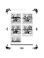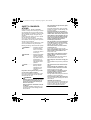
1
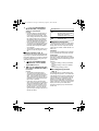
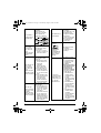
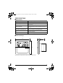
00_CV_3P124623-5C.fm Page 1 Saturday, July 30, 2005 8:10 PM OPERATION MANUAL SCHEDULE TIMER MODELS DST301BA61 Thank you for purchasing Daikin’s schedule timer. For proper usage, read this manual carefully before using this unit. This manual will help you with anything you can not understand or should anything go wrong with the unit during use. Keep this manual handy for the future reference. 00_CV_3P124623-5C_2.fm Page 1 Wednesday, August 3, 2005 4:53 PM 4 6 5 3 1 2 7 8 DST301BA61 9 10 11 1 12 15 14 16 17 DST301BA61 13 18 19 20 2 [1] 00_CV_3P124623-5C_2.fm Page 2 Wednesday, August 3, 2005 4:53 PM 1·8 2 2 3 1 4 3 4 3 7 DST301BA61 6 5 DST301BA61 4 1·8 2 5 3·7 4 5·6 DST301BA61 7 5 7 [2] DST301BA61 6 6 01_EN_3P124623-5C.fm Page 1 Wednesday, August 3, 2005 2:20 PM SAFETY CONSIDERATIONS Please read these “ SAFETY CONSIDERATIONS ” carefully before installing air conditioning equipment and be sure to install it correctly. After completing the installation, make sure that the unit operates properly during the start-up operation. Please instruct the customer on how to operate the unit and keep it maintained. Also, inform customers that they should store this installation manual along with the operation manual for future reference. This air conditioner comes under the term “ appliances not accessible to the general public ”. Meaning of warning, caution and note symbols. WARNING............. Indicates a potentially hazardous situation which, if not avoided, could result in death or serious injury. CAUTION ............. Indicates a potentially hazardous situation which, if not avoided, may result in minor or moderate injury. It may also be used to alert against unsafe practices. NOTE ................... Indicates situation that may result in equipment or property-damage-only accidents. Keep these warning sheets handy so that you can refer to them if needed. Also, if this equipment is transferred to a new user, make sure to hand over this operation manual to the new user. WARNING In order to avoid electric shock, fire or injury, or if you detect any abnormality such as smell of fire, turn off power and call your dealer for instructions. Ask your dealer for installation of the air conditioner. Incomplete installation performed by yourself may result in a water leakage, electric shock, and fire. 1 Ask your dealer for improvement, repair, and maintenance. Incomplete improvement, repair, and maintenance may result in a water leakage, electric shock, and fire. Improper installation or attachment of equipment or accessories could result in electric shock, short-circuit, leaks, fire or other damage to the equipment. Be sure only to use accessories made by Daikin which are specifically designed for use with the equipment and have them installed by a professional. Ask your dealer to move and reinstall the air conditioner or the remote controller. Incomplete installation may result in a water leakage, electric shock, and fire. Never let the indoor unit or the remote controller get wet. It may cause an electric shock or a fire. Never use flammable spray such as hair spray, lacquer or paint near the unit. It may cause a fire. Never replace a fuse with that of wrong ampere ratings or other wires when a fuse blows out. Use of wire or copper wire may cause the unit to break down or cause a fire. Never inspect or service the unit by yourself. Ask a qualified service person to perform this work. Cut off all electric waves before maintenance. Do not wash the air conditioner or the remote controller with excessive water. Electric shock or fire may result. Do not install the air conditioner or the remote controller at any place where flammable gas may leak out. If the gas leaks out and stays around the air conditioner, a fire may break out. Do not touch the switch with wet fingers. Touching a switch with wet fingers can cause electric shock. CISPR 22 Class A Warning: This is a class A product. In a domestic environment this product may cause radio interference in which case the user may be required to take adequate measures. 01_EN_3P124623-5C.fm Page 2 Wednesday, August 3, 2005 2:20 PM CAUTION After a long use, check the unit stand and fitting for damage. If they are left in a damaged condition, the unit may fall and result in injury. Do not allow a child to mount on the unit or avoid placing any object on it. Falling or tumbling may result in injury. Do not let children play on and around the unit. If they touch the unit carelessly, it may result in injury. Do not place a flower vase and anything containing water. Water may enter the unit, causing an electric shock or fire. Never touch the internal parts of the controller. Do not remove the front panel. Some parts inside are dangerous to touch, and a machine trouble may happen. For checking and adjusting the internal parts, contact your dealer. Avoid placing the controller in a spot splashed with water. Water coming inside the machine may cause an electric leak or may damage the internal electronic parts. Do not operate the air conditioner when using a room fumigation - type insecticide. Failure to observe could cause the chemicals to become deposited in the unit, which could endanger the health of those who are hypersensitive to chemicals. Safely dispose of the packing materials. Packing materials, such as nails and other metal or wooden parts, may cause stabs or other injuries. Tear apart and throw away plastic packaging bags so that children will not play with them. If children play with a plastic bag which was not torn apart, they face the risk of suffocation. Do not turn off the power immediately after stopping operation. Always wait at least five minutes before turning off the power. Otherwise, water leakage and trouble may occur. The appliance is not intended for use by young children or infirm persons without supervision. The remote controller should be installed in such away that children cannot play with it. NOTE Never press the button of the remote controller with a hard, pointed object. The remote controller may be damaged. Never pull or twist the electric wire of the remote controller. It may cause the unit to malfunction. Do not place the controller exposed to direct sunlight. The LCD display may get discolored, failing to display the data. Do not wipe the controller operation panel with benzine, thinner, chemical dustcloth, etc. The panel may get discolored or the coating peeled off. If it is heavily dirty, soak a cloth in water-diluted neutral detergent, squeeze it well and wipe the panel clean. And wipe it with another dry cloth. Dismantling of the unit, treatment of the refrigerant, oil and eventual other parts, should be done in accordance with the relevant local and national regulations. 2 01_EN_3P124623-5C.fm Page 3 Wednesday, August 3, 2005 2:20 PM CONTENTS SAFETY CONSIDERATIONS ...........1 FEATURES AND FUNCTIONS ........3 NAMES AND FUNCTIONS OF OPERATING SECTION .......................4 OPERATION .............................................5 Setting present time ........................................5 Setting no. of programmed time......................6 Change and cancellation of no. of programmed time............................................7 Manual operation ............................................9 Operation control code ...................................9 Error diagnosing function................................9 QUESTION AND ANSWER .............10 SPECIFICATIONS ...............................12 Specifications................................................12 Outline drawings ...........................................12 FEATURES AND FUNCTIONS n Operation controlled by programmed time Operating time and stopping time can be set to the minute by each day of the week. The operating and stopping patterns can also be set in schedule according to the time slot given twice a day in tune with the uses. See page 5—9. n Unified Operation/Stop By using this schedule timer, the unified operation/stop of the indoor unit can be executed manually regardless of the No. of programmed time in operation. See page 9. • When used in conjunction with central remote controller (Optional Accessory) The operation controlled by programmed time can be set for up to eight different patterns (timer No. 1 – 8). Each schedule pattern can be also selected. 3 01_EN_3P124623-5C.fm Page 4 Wednesday, August 3, 2005 2:20 PM NAMES AND FUNCTIONS OF OPERATING SECTION (Fig. 1, 2) UNIFIED OPERATION BUT- 1 TON “ 3 “ ” 4 5 10 Press this button to perform the unified stop regardless of the No. of programmed time. OPERATION LAMP (RED) ” (TIME NO.) Displays the time No. only when used in conjunction with the central remote controller. DISPLAY “PROGRAM START.” (PROGRAMMING START) 11 6 7 8 Lights above the day of the week set as holiday. The operation controlled by timer is not available on that day. DISPLAY “ — ” (SETTING OF DAYS OF A WEEK) Flashes below the day of the week programmed. DISPLAY “ ” (MALFUNCTION CODE) Displays the contents of malfunction during the stop due to malfunction. DISPLAY “ ” (PROGRAMMED TIME OF SYSTEM OFF) Displays the time programmed to stop. 12 TIME NO. BUTTON “ ” See page 5–9. CLOCK ADJUSTING 13 BUTTON “ ” Press this button to set the present time. The light turns on when the timer is programmed. DISPLAY “ OFF ” (HOLIDAY SETTING) DISPLAY “ ” (PROGRAMMED TIME OF SYSTEM START) Displays the time programmed to start. The light turns on during the operation of the indoor unit. DISPLAY “ ” Displays the present day of the week and time. Press this button to perform the unified operation regardless of the No. of programmed time. UNIFIED STOP BUTTON 2 DISPLAY “ 9 (PRESENT TIME) ” PROGRAMMING START 14 BUTTON “ ” Press this button to set or check the No. of programmed time. Press it again after you are through with the program. BUTTON FOR SELECTING 15 DAYS OF A WEEK “ ” Press this button to select the day of the week. HOUR/MINUTE BUTTON 16 “ ” Press this button to adjust the present time and the programmed time. 4 01_EN_3P124623-5C.fm Page 5 Wednesday, August 3, 2005 2:20 PM 2. 17 TIMER ON BUTTON “ ” Press this button to set the present time and the programmed time. (NOTE) • The display “ MON ” follows the display “ SUN. ” HOLIDAY SETTING 18 BUTTON “ 2 Press the BUTTON FOR SELECTING DAYS OF A WEEK. Each time the button is pressed, the day display shifts to the right. ” Press this button to set holidays. BUTTON FOR COPYING PROGRAM OF PREVIOUS 19 DAY “ Set the day to Friday. 3. ” Use this button to set the No. of programmed time same as that of the previous day. PROGRAM CANCELING 20 BUTTON “ 3 Set the time with the HOUR/ MINUTE BUTTON. Each time the HOUR/MINUTE BUTTON is pressed, the display is put forward minute by minute and hour by hour. When the button is kept pressed, the display is put forward continuously. (NOTES) • After becoming “ AM 11:00 ”, when the button is pressed, the display becomes “ PM 0:00 ”. • After becoming “ 59 ” (minute), when the button is pressed, the display becomes “ 00 ” (minute). ” Use this button to set the programmed time to cancel. The display shows “ – ; – – ”. (Note) 1. Please note that all the displays in the figure appear for explanation purpose or when the cover is open. Set the time to 5:30 p.m. OPERATION Setting present time (Fig. 3) (Example) 1. In case of setting Friday, 5:30 p.m. 1 Press the CLOCK ADJUSTING BUTTON. The present time display flashes. (NOTE) • The present time needs adjusting in case of turning power supply on for the first time or the occurrence of power failure over the period of 48 hours or more. 5 4. 4 Press the TIMER ON BUTTON the moment the time signal of TV, radio, telephone, etc. is heard. The mark “ : ” flashes, and the clock starts. Press the TIMER ON BUTTON in tune with the time signal at 5:30 p.m. (NOTES) • The clock used is of 12-hour type. • When you turn power supply on, the system may display “ ” for about one minute and not start to operate after all the liquid crystal displays appear at a time. • If the CLOCK ADJUSTING BUTTON is pressed by mistake, press it again to return to the original state. As the clock does not stop, the time indicated by the clock is kept correct. In case of power failure within 48 hours, the clock keeps operating by utilizing the built-in battery. 01_EN_3P124623-5C.fm Page 6 Wednesday, August 3, 2005 2:20 PM Setting no. of programmed time (Fig. 4) (Example) (1) Setting programmed time 4. Time No. 5 (to be programmed only when used in conjunction with the central remote controller) Monday to Friday: Operating from 8:45 a.m. till 5:00 p.m. Operating from 5:15 p.m. till 11:00 p.m. Saturday and Sunday: Setting the whole day stop operation (application for holidays) controlled by programmed time. 1. Press the PROGRAMMING START BUTTON. Programming is available. The display “ PROGRAM START ” appears, and the display of days of a week flashes. 4 Set the programmed time of system start 1 by using the HOUR/ MINUTE BUTTON. Each time the HOUR/MINUTE BUTTON is pressed, the display is put forward minute by minute and hour by hour. When the button is kept pressed, the display is put forward continuously. Set the “PROGRAMMED TIME OF SYSTEM START 1” at 8:45 a.m. 1 5. 5 Press the TIMER ON BUTTON, and set the programmed time of system start 1. Each time you press it, the next area to be set flashes. (NOTE) • Set the other programmed time in the same procedure. 2. 2 Press the TIME No. BUTTON, and select the desired number. (NOTE) • Unless used in conjunction with the central remote controller, The TIME No. is not displayed and can not be selected. Select the TIME No. 5. 3. 3 Press the BUTTON FOR SELECTING DAYS OF A WEEK, and set the proper day of the week. Each time you press it, the flashing display of days of a week shifts to the right. Set to Monday. 6 01_EN_3P124623-5C.fm Page 7 Wednesday, August 3, 2005 2:20 PM (2) Set the next day of the week. • The flashing display goes off, and the No. of programmed time of the present day is displayed. Then the operation controlled by timer starts. • The operation controlled by timer is executed even while the program is being set. Set the day of the week to Tuesday, and copy the program of the previous day (Monday). In the same procedure, set the day of the week to Wednesday through Friday in sequence. 6. 6 Press the BUTTON FOR SELECTING DAYS OF A WEEK and set the following day. Press the BUTTON FOR COPYING PROGRAM OF PREVIOUS DAY. The same program as that of the immediately preceding day of the week is set. (NOTE) • Repeat each procedure 3 – 5 in the above when not copying the contents of the previous day. This is the end of the setting example. Change and cancellation of no. of programmed time (Fig. 5) (Example) (3) Holiday setting 7. 7 Press the BUTTON FOR SELECTING DAYS OF A WEEK and set one or more days of the week as holiday. Press the HOLIDAY SETTING BUTTON, and the display “ OFF ” is displayed at the top of the day of the week. If you press it again, the display returns to the original state. Set Saturday and Sunday as holidays. 8. Operating from 5:15 p.m. till 11:00 p.m. A: Change/ cancel partially B: Cancel the whole (Wednesday) After operating from 8:45 a.m. till 7:00 p.m., the operation stops. (Thursday) Whole day stop. 1. 1 Press the PROGRAMMING START BUTTON. The program setting is ready. The display “ PROGRAM START ” appears, and the display of days of a week flashes. 2. 2 Press the TIME No. BUTTON, and select the desired No. 8 Press the PROGRAMMING START BUTTON, and finish the program setting. (NOTES) • Unless the button is pressed within 20 minutes, the display will automatically revert back to the original state. In this case, setting contents up to the point where the TIMER ON BUTTON (or HOLIDAY SETTING BUTTON or BUTTON FOR COPYING PROGRAM OF PREVIOUS DAY) is pressed will only take effect. • The display “ PROGRAM START ” and the display of days of a week “ — ” disappears. 7 Operating from 8:45 a.m. till 5:00 p.m. Time No. 3 (to be set only when used in conjunction with the central remote controller) Select the time No. 3. 01_EN_3P124623-5C.fm Page 8 Wednesday, August 3, 2005 2:20 PM 3. 3 Press the BUTTON FOR SELECTING DAYS OF A WEEK, and set the day of the week to be changed. The set No. of programmed time of the day of the week is displayed. 6. 6 Press the PROGRAM CANCELING BUTTON, and cancel the programmed time. If you press it again, display returns to the original state. Press the TIMER ON BUTTON to finalize the cancellation. Set the day to Wednesday. Shift to the “PROGRAMMED TIME OF SYSTEM START 2”. A. Change/cancel partially 4. 4 Press the TIMER ON BUTTON and change, and the display of programmed time flashes. Each time you press it, the next area to be set flashes. Set the “PROGRAMMED TIME OF SYSTEM START 2” to program cancellation. In the same procedure, cancel the programmed time of system off 2. Shift to the display “PROGRAMMED TIME OF SYSTEM OFF 1”. 5. 5 Press the HOUR/MINUTE BUTTON and change the programmed time. Press the TIMER ON BUTTON, and finalize the setting of change. B. Cancel the whole 7. 7 Press the BUTTON FOR SELECTING DAYS OF A WEEK, and shift to the day of the week to be canceled. Then, press the HOLIDAY SETTING BUTTON, the display “ OFF ” appears at the top of the particular day of the week. The programmed time is canceled. If you press the button again, the display returns to the original state. Change the “PROGRAMMED TIME OF SYSTEM OFF 1” to 7:00 p.m. Shift the day of the week to Thursday to set as a holiday. 8 01_EN_3P124623-5C.fm Page 9 Wednesday, August 3, 2005 2:20 PM 8. 8 Press the PROGRAMMING START BUTTON. The program setting is now finished. (NOTES) • Unless the button is pressed within 20 minutes, the display will automatically revert back to the original state. In this case, setting contents to the point where the TIMER ON BUTTON (or HOLIDAY SETTING BUTTON or BUTTON FOR COPYING PROGRAM OF PREVIOUS DAY) is pressed will only take effect. • To continue the change/cancellation, do not press the PROGRAMMING START BUTTON until all change/cancellation are completed. • The operation controlled by timer is executed even while the program is being set. Manual operation (Fig. 6) This schedule timer enables the operation/stop by pressing the UNIFIED OPERATION/STOP BUTTON in addition to the operation controlled by timer (operation/stop according to the programmed time) at any time. 1. Press the UNIFIED OPERATION BUTTON, and the OPERATION LAMP turns on. 2. Press the UNIFIED STOP BUTTON, and the OPERATION LAMP is turned off. (NOTES) • The operation automatically stops according to the programmed time of system off even during the manual operation. In the meantime, the operation starts automatically according to the programmed time of system start even during the stop of operation. • If the unit is used in conjunction with other optional controllers for centralized control, the OPERATION LAMP of the unit that is not under operation control may be turned on or off a few minutes behind schedule. This shows that the signal is being exchanged, and does not indicate any failure. 9 Operation lamp Turn on: The light turns on when any of the indoor units is in operation whether the operation is controlled by timer or by hand. Turn off: The light turns off when all the indoor units stop. Operation control code Two different types of operation control codes can be selected when this kit is used independently (when not used in conjunction with the central remote controller, unified ON/OFF controller, etc.). Individual In case where the operation/stop is controlled by both schedule timer and remote controller. Centralized The operation is controlled by the schedule timer alone, and the operation/stop is controlled freely with the remote controller during the programmed time. (NOTES) • For current settings, contact your DAIKIN dealer. • To change settings, contact your DAIKIN dealer. Do not change settings yourself. Error diagnosing function (Fig. 7) This schedule timer is provided with the malfunction diagnosing function. The malfunction code flashes if there occurs any malfunction in communication, etc. between and among the optional controllers for centralized control. In addition, the operation lamp also flashes if there occurs any malfunction in communication with the indoor unit. Check the contents of the display and contact your DAIKIN dealer because the signals give you the idea of the trouble area. 01_EN_3P124623-5C.fm Page 10 Wednesday, August 3, 2005 2:20 PM Operation lamp Malfunction code Address failure of schedule timer. Contents of malfunction Failure of PC board of schedule timer. Turn off Turn on or off M1 Fixes The following causes are possible. Check each one. 1. PC board problems Turn on or off MC Malfunction of transmission between each optional controllers for centralized control. M8 Fixes Check all central devices which are connected (e.g., power supply, transmission wiring, etc.). Malfunction of transmission between indoor unit and optional controllers for centralized control. Flash UE Improper combination of optional controllers for centralized control. Turn on or off MA Fixes The following causes are possible. Check each one. 1. Are all central devices combined correctly? 2. Is the master central connector attached to two or more central devices? 3. Are there 128 or more indoor units connected? Fixes The following causes are possible. Check each one. 1. Do the control range addresses in the central remote controller overlap? 2. Do the control range addresses in the on/off controller overlap? 3. Are there 2 or more schedule timers connected? Flash — Fixes Inspect all indoor units which are displaying an error (e.g., power supply, transmission wiring, etc.). Malfunction in indoor unit (Refer to the malfunction codes of the indoor remote controller, while also read the “ CAUTION FOR SERVICING ” attached to the indoor unit.) QUESTION AND ANSWER Question It is possible to make settings twice a day, but is it possible to make only the “ off ” setting? (To avoid forgetting to turn the unit off.) Answer Yes. Press the PROGRAM CANCELING BUTTON in the “ ” section in order to set it to “ OFF ”. 10 01_EN_3P124623-5C.fm Page 11 Wednesday, August 3, 2005 2:20 PM Is it possible to set times which straddle days? Yes, it is possible. Example: Start operation at 5:00 a.m. on Sunday Stop operation at 6:00 p.m. on Monday The TIME NO. is not displayed. The following causes are possible. 1. The TIME NO. is not displayed when using the schedule timer alone. (It can be set if using the central remote controller at the same time.) The display remains The unit does not turn on even though the set “ on ” time has come. (When using the schedule timer alone) The following causes are possible. 1. Are the “ on ” time and the “ off ” time set to the same time? The unit does not turn on even though the set “ on ” time has come. (When using the unit with a central remote controller) The following causes are possible. Check each one. 1. Was the timer number set with the central remote controller? Was an incorrect timer number set? 2. Is another timer no. set with the central remote controller set for “ off ” at the same time? 3. Is the operation code set to “ remote control permission timer ” using the central remote controller or the on/off controller? The unit operates even though that day is set as a holiday. (When using the unit with a central remote controller) 11 “ The following causes are possible. 1. Is another timer number set with the central remote controller set for “ on ” at the same time? (If two timer numbers are set, make sure that the settings for holidays and working days do not overlap between the different timer numbers.) ” even though I push the HOUR/MINUTE BUTTON in the timer program settings. I cannot set “ central management priority ” or “ after-push priority ” with the schedule timer. The following causes are possible. 1. Is the day set to a holiday? The following causes are possible. 1. Is a central remote controller or on/off controller also installed? ∗ The priority order of the operation codes depends on the central devices which are installed. The below operation codes are set. • Schedule timer Central remote controller is used as well Operation code of the central remote controller • Schedule timer On/off controller is used as well Operation code of the on/off controller • Schedule timer Central remote controller On/off controller is used as well Operation code of the central remote controller 01_EN_3P124623-5C.fm Page 12 Wednesday, August 3, 2005 2:20 PM SPECIFICATIONS Specifications Display of time 12-hour digital display Clock cycle type Quartz clock type Clock accuracy Within ±30 sec./month (environmental temperature from 15°C to 35°C) Timer programming Two pairs of programmed time for both system start and system off can be set in units of minute for each day of the week Power failure compensation time Approximately 48 hours for a single occurrence of power failure (clock with No. of programmed time) Size 120 (W) × 120 (H) × 53 (D) mm (Width/Height/Depth) Weight Approximately 210g Outline drawings 120 16 37 71 120 Specifications and appearance subject to change without notice. 12 00_CV_3P124623-5C.fm Page 2 Saturday, July 30, 2005 8:10 PM 3P124623-5C EM05A041 (0509) HT