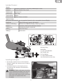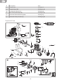
1
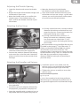
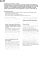
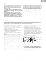
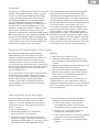
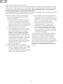
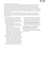
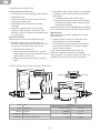
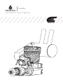
20GX2
Evolution Gas Engines
®
NOTICE
All instructions, warranties and other collateral documents are subject to change at the sole
discretion of Horizon Hobby, LLC. For up-to-date product literature, visit horizonhobby.com
and click on the support tab for this product.
Meaning of Special Language
The following terms are used throughout the product literature to indicate various levels
of potential harm when operating this product:
NOTICE: Procedures, which if not properly followed, create a possibility of physical property
damage AND a little or no possibility of injury.
CAUTION: Procedures, which if not properly followed, create the probability of physical
property damage AND a possibility of serious injury.
WARNING: Procedures, which if not properly followed, create the probability of property
damage, collateral damage, serious injury or death OR create a high probability of
superficial injury.
WARNING: Read the ENTIRE instruction manual to become familiar with the features of
the product before operating. Failure to operate the product correctly can result in
damage to the product, personal property and cause serious injury.
This is a sophisticated hobby product and NOT a toy. It must be operated with caution and
common sense and requires some basic mechanical ability. Failure to operate this Product in a
safe and responsible manner could result in injury or damage to the product or other property.
This product is not intended for use by children without direct adult supervision. Do not use with
incompatible components or alter this product in any way outside of the instructions provided by
Horizon Hobby, LLC. This manual contains instructions for safety, operation and maintenance. It
is essential to read and follow all the instructions and warnings in the manual, prior to assembly,
setup or use, in order to operate correctly and avoid damage or serious injury.
CAUTION: This product can become extremely hot when in use, which could lead
to burns.
Age Recommendation: Not for children under 14 years. This is not a toy.
Safety Warnings
Model engines produce a substantial amount of power, which can create unsafe situations if not
used correctly. Always use common sense and observe all safety precautions when operating,
handling or performing any procedure involving your engine. Failure to follow safety precautions
could result in serious injury and property damage.
• Always ensure spectators, especially children, are at least 30 feet away when running
the engine.
• Always ensure that the propeller is securely attached to the engine shaft and all retaining
fasteners are tightened properly before EACH flight. Use of blue threadlock to tighten nuts
is advisable.
• Always keep small parts out of the reach of children as they can be choking hazards.
• Always secure the airplane before powering the engine.
• Always keep your face and body away from the path of the propeller blades when starting
or running your engine.
• Always stand behind the propeller when making carburetor adjustments.
• Always wear safety glasses or goggles when starting and running your engine.
• Always keep your fuel in a safe place away from sparks, heat or anything that can ignite.
• Always ensure the aircraft is secure and will not move once the engine is started.
• Always rebind your transmitter to your receiver(s) after setup and before first flight.
• Always ensure the throttle failsafe is set to low throttle in your transmitter.
2
• Always perform a range check prior to flight.
• Always use the throttle linkage to shut off the air or turn off the engine power switch to stop
the engine.
• Never use hands, fingers, or any other body part to stop the propeller.
• Never throw any object into a propeller to stop it.
• Never run the engine in the vicinity of loose small objects, such as gravel or sand, to avoid
the propeller uncontrollably throwing such materials.
• Never wear loose clothing or a loose neckstrap when operating your model engine as these
items could become entangled in the propeller.
• Never have loose objects such as screwdrivers, pencils, etc. in your pockets when operating
your model engine. These could fall into the propeller.
• Never allow fuel to come into contact with eyes or mouth. Gasoline and other fuels used
in model engines are poisonous.
• Always ensure gasoline and fuel are stored in a clearly marked container away from
the reach of children.
Precautionary Guidelines
• Always mount the engine securely on a bench mount or high-quality engine mount.
• Always use the correct size and pitch of propeller for your engine. Refer to the Propeller Chart
in this manual.
• Always confirm proper balance of your propeller prior to installation of the engine. Failure
to do so could result in damage to the engine and/or airframe.
• Always utilize an electric starter to start your engine.
• Always discard any propeller that is nicked, scratched, cracked or damaged in any way.
• Always run your model engine in a well-ventilated area. Model engines can produce possibly
harmful carbon monoxide fumes.
• Always store your fuel safely in a sealed, water-resistant container.
• Always store fuel in a cool, dry location. Do not allow fuel containers to come in direct
contact with concrete, as the fuel may absorb moisture.
• Always responsibly discard fuel if there is condensation and/or water inside the fuel
container.
• Never return unused fuel from the fuel tank back into the fuel container.
• Never attempt to repair or modify a propeller beyond its intended use.
• Never handle model engines, mufflers and/or tuned pipes until they have had time to cool.
They can become extremely hot when in use.
3
Introduction
Congratulations on your purchase one of the exciting new engines in the Evolution® small
block gas engine series. All of the Evolution brand gas engines are designed from the start to
provide you with excellent performance at a fraction of your previous operating costs. We have
painstakingly designed and tested each engine to ensure a hassle-free experience without
giving away anything in expected performance or durability. This manual, when read and
followed, will guide you through the simple steps to your success. Welcome to the Evolution
family.
Small Block Gas Engine Design
Starting with our already proven glow engines enjoyed by thousands around the world, we
endeavored to take that excitement and experience into the realm of gasoline fuel to provide
you with a complete package; great performance and low cost of operation.
Step 1 Start with a great engine. The Evolution glow engines have provided thousands of users
excellent performance.
Step 2 D
esign a new carburetor system that will be reliable and provide for hassle-free use by
the owners. This new carburetor, with already proven technology, was modified to fit in
the available space in front of the cylinder and the unique needs of a gasoline fueled
engine. Built onto the front of the carburetor is a fuel-pressure regulator. On the back of
the carburetor is a new crankcase-driven pump. This pump helps maintain constant fuel
pressure as well as draw fuel to the carburetor. A new cat’s eye style fuel metering system
was added to allow for more controllability to the low and mid-range throttle positions.
Step 3 Design the proper muffler system to handle the extra heat and expansion of the burnt gas
mixture when compared to a glow system. We decided to include an inverted wraparound
muffler that would make a more compact and clean installation. We also repurposed the
fuel pressure nipple and utilized this for a smoke inlet for those users who would like to
have smoke on-board their airplane. The new dual exhaust outlets provide a deeper yet
quieter sound.
Step 4 D
esign operating accessories that enhance the user experience. During our extensive
2 1/2-year testing program we discovered a lot of new techniques and obstacles that are
unique to gasoline fueled small block engines.
• Because the amount of fuel consumed is one third that of a comparable sized
glow engine, the construction and reliability of the fuel delivery system to the
carburetor becomes three times as critical. Microscopic pieces of dirt that
used to safely pass through the larger fuel passages of a glow carburetor will
wreak
havoc on a gasoline system.
The same holds true for air bubbles from the tank or any small leak in the fuel
tubing; what would pass harmlessly through a glow carburetor simply is not
tolerated in a gasoline system because the air bubbles are effectively three
times the size they used to be. We have sourced an excellent sintered plastic
clunk that, when used in the tank, stops all air bubbles in the fuel line as
well as filters out any dirt in the fuel system. The included clunk is critical to
ensuring successful and reliable operation.
• We found that high temperatures destroy normal Tygon® tubing (the go-to
choice for gasoline engines) within minutes. We found that Neoprene tubing
would withstand the temperatures but it tended to degrade quickly in use. We
recommend using FKM or Viton® tubing in your fuel system plumbing. FKM
tubing is specifically formulated to withstand high temperatures and harsh
petrol-based chemicals, such as gasoline.
4
Included Content
Engine
EVOA107
Evolution®/Spektrum™ Telemetry RPM Adapter Cable
EVOA121
Sintered Plastic Filter Clunk
EVOG10300
Ignition Unit
EVOG10350
Spark Plug
EVOG20601B
Muffler
EVO110E100A
Muffler Screws & Gasket
Optional Items
APC15060 (APC16060) 15 x 6 propeller (break-in) (16 x 6 propeller (normal flight))
EVOA100
Optical Electronic Ignition Kill Switch
EVOA102 (EVOA103)
Medium Gas-FKM Fuel Tubing 1 meter (3 meters)
EVOA112
Evolution 3 Wire Ignition/Receiver Switch
EVOX1001Q
Evolution Synthetic 2-Cycle Oil
HAN155
Ultra Fuel Pump
HAN156
Tachometer
C
G
B
D
E
A
F
A.Spark Plug
B.Muffler
C.Low-speed Needle
D.Throttle Arm
E. Fuel Nipple
F. High-speed Needle
G.Crankcase Pressure Port
Installing the Engine
1. Secure the engine mount on the airplane
firewall. Tighten the engine mount screws in
the firewall.
2.Install the engine on the engine mount
according to the airplane manufacturer’s
instructions.
WARNING: Tighten all engine mounting
screws before each flight. If you do not
tighten the engine mounting screws,
the screws may vibrate loose and cause
the engine to separate from the
fuselage.
5
Installing the Muffler
1. Put a lock washer on each of the muffler
screws. Push the muffler screws through the
muffler.
2.Align the muffler gasket with the exhaust
opening and the muffler mounting screws.
3. Tighten the muffler screws.
Important: Tighten the muffler screws after
the first few tanks of fuel. The muffler screws
may loosen from heat and vibration. After the
third tightening, no further muffler loosening
should occur.
The muffler mounting accessory package
includes mounting screws (2), lock washers
(2), muffler gaskets (2) and L- wrenches (3).
Connecting the Throttle Linkage
11mm
Mid-throttle
1. Use a secure method to attach the
throttle linkage to the throttle arm on the
carburetor.
2.Power on the transmitter and receiver.
3. Move the throttle stick to the middle stick
position.
4.Adjust the throttle arm so the arm is 90
degrees to the throttle pushrod.
5. Center the throttle servo. Install a servo arm
with a hole 11mm (7/16 in) from the center
of the arm.
6.Use a clevis to attach the throttle linkage to
the servo arm.
6
Adjusting the Throttle Opening
4.Move the throttle stick and throttle
1. Lower the throttle and center the throttle
trim down to confirm the throttle closes.
trim.
2.Adjust the length of the throttle linkage until 5. If you reversed the throttle channel in your
transmitter and you are using a 2.4GHz radio
the throttle is open 1mm.
system, you must re-bind your radio system
3. Move the throttle stick up to confirm the
to set the correct failsafe position.
throttle opens. If the throttle does not
open, reverse the throttle channel in your
transmitter.
Attaching the Fuel Lines
A. If using a three-line tank, connect medium
diameter fuel tubing to the third line and
route this line to a convenient location for
fueling/de-fueling your model.
B. If using a two-line tank, connect a “T”
fitting inline with the carburetor supply
line and route one side of the “T” to a
convenient location for fueling/de-fueling
your model.
Crankcase
Pressure Line
We recommend using a fuel filler like the one
Fuel Inlet Line included in the Hangar 9® Fuel Filler with “T”
Fitting and Overflow Fitting (HAN116), which
1. Connect medium diameter fuel tubing to the
also includes a vent line connector. This
carburetor and the fuel tank supply line.
package makes it convenient to setup your fuel
2.Connect the medium diameter fuel tubing
system whether using a two- or a three-line fuel
to the vent line in the fuel tank. Route the
tank. We also recommend using medium
other end of this line to the outside of the
diameter FKM fuel tubing for all plumbing in
fuselage.
your fuel setup.
Attaching the Propeller and Spinner
4.Install the spinner cone. Make sure the
spinner cone is not touching the propeller.
Trim the propeller opening if necessary.
5. Tighten the spinner screw(s) to secure the
spinner cone.
Recommended Propellers
15 x 6–17 x 8
16 x 6 has tested to be the best performer
with this engine, although the performance is
very good throughout the recommended range.
1. Remove the prop nut and prop washer from
the crankshaft.
2.Install the spinner backplate, followed by
the propeller, prop washer and prop nut.
3. Cover the propeller with a cloth and use an
adjustable wrench to tighten the prop nut.
7
Connecting the Electronic Ignition
The Evolution Electronic Ignition Assembly is designed and engineered specifically for the
small block engine series. It is smaller and lighter so it fits into tighter spaces of the airplanes
the engines are designed to power. The battery voltage required is between 4.8V (4-cell Ni-MH
pack) and 8.4V (2S Li-Po battery) and no voltage regulators are needed with any of these
batteries. We recommend a 2S Li-Fe or Li-Po battery with a capacity of at least 800mAh. The
maximum amp draw at full throttle is 450mA, and our more typical average has been between
250–300mA.
The assembly consists of
• Ignition module with battery connector, ignition sensor connector, tachometer readout
connector and spark plug connector
• Ignition sensor (already attached to your engine)
• Sensor magnet (already installed in the prop drive hub of your engine)
Mounting Your Electronic Ignition
• You can mount the unit in any orientation
and place that is convenient for your
installation. The module is sized to
conveniently fit into the tank compartment
of most glow powered airplanes alongside
or underneath the recommended fuel tanks.
You can also mount it to the firewall or
under the engine firewall extension if your
airplane is so equipped. Keep in mind that
it should be mounted away from the heat of
the muffler.
• Secure the ignition module to your chosen
location with foam padding to provide
vibration isolation. We typically mount it
conveniently with tie wraps after wrapping
the ignition in lightweight 1/4-inch foam
rubber.
• You may need to route both the spark plug
connector wire and the ignition sensor wire
through the firewall, so be sure to plan
ahead and provide adequately sized holes
that will allow you to pull either the ignition
sensor connector or the spark plug cap
connector through the holes for later
ignition removal.
• Mount a good quality radio receiver type
switch between the ignition unit and the
battery. We recommend the Evolution
3-Wire Ignition/Receiver Switch (EVOA112).
Mount this switch in a convenient place
on the outer fuselage close to the front
of the airplane to make it easy to turn the
ignition on and off. Being able to easily
shut off the ignition is an important safety
consideration.
• For added security and controllability, add
an additional radio-operated kill switch
(such as the Optical Ignition Kill Switch
EVOA100) between the ignition battery
connector lead and the ON/OFF switch.
• Connect the ignition sensor wire to the
ignition module. The sensor wire will only
fit into one of the connectors so you cannot
connect it wrong.
• Connect the ON/OFF switch to the battery
connector lead of the ignition module. This
connector is the red connector.
• If desired, you can connect either the
separately available tachometer readout or
the included Evolution/Spektrum Telemetry
Adapter Cable (EVOA107) to the tachometer
readout connector. Plug the other end of
the adapter cable into a Spektrum telemetry
module’s rpm input port.
• Connect the spark plug connector to the
spark plug. This adapter has a push on and
rotate clockwise 1/6 turn locking mechanism
to ensure a solid connection. If the spark
plug is not secured as described above,
you will likely experience radio interference.
Always perform a radio check with the
engine running to ensure the ignition is not
causing interference with your radio.
• Make sure you charge your ignition battery.
You are now ready to operate your electronic
ignition with the engine.
8
Fuel
This engine requires a mix of 20:1 gas to oil
lubricant ratio for break-in and a mix of 32:1
gas/oil ratio for normal operation in order to
last a long time.
The needle bearing at the bottom end of the
conrod depends upon this lube ratio to operate
properly.
Do not go leaner than a 20:1 gas/oil ratio
for the first gallon of fuel. After this you may
decrease the oil content to a 32:1 gas/oil ratio
if desired. Do not go leaner than a 32:1 gas/
oil ratio or the warranty on your engine will be
voided.
To properly mix the fuel, for a mix of 20:1 gas to
oil, add 6.75 oz of good quality 2-stroke oil to
one gallon (or 53 mL of oil to one liter) of 87–93
octane fuel. (EVOX1001Q Evolution 2-stroke oil
is recommended) We prefer to add the oil first
to our fuel container and to add the gasoline
second. This helps to ensure a good mixture of
the oil with the fuel at the outset.
We have tested our own Evolution 2-stroke oil,
Valvoline, Shell, RedLine and Husqvarna oils.
Other quality 2-stroke oils should work as well.
Fuel Delivery System
It is very important to properly construct your fuel supply system to the engine to avoid
operating problems. Our experience has shown that many seemingly engine related operating
problems are in fact fuel delivery problems, not engine related problems.
Fuel Filtering - Because of the incredibly small
amount of fuel that is being used by this
engine, filtration of the fuel is mandatory in two
different spots in the system:
1. Between the fuel jug and the tank.
2.Within the fuel tank itself (with a sintered
plastic filter clunk EVOA121).
One of these filters is included with your
engine.
Tank Location - Because there is a crankcase
pressure-driven pump on the carburetor, tank
location is less critical than with a muffler
pressure-driven system; however, it is still
good practice to mount the fuel tank in line
with the carburetor, and as close to the rear of
the engine as possible.
Care taken in mounting the tank as
described will provide trouble free operations
in all flight attitudes.
Tank Choice and Construction - Choose a tank
between 8–14 oz (240–420 mL). These tanks
will yield 12 minutes (for the smaller tank) to
25 minutes (for the larger tank) of full throttle
flying time.
• Ensure you use a tank stopper made for use
with gasoline and/or smoke oil.
• We suggest a three-line tank system; one
for the line to the carburetor with the clunk
attached internally, one for the vent line
to the atmosphere, and one dedicated to
fueling/defueling the tank. We try to avoid
the T-fittings and other inline valves because
they can be a possible source of air/fuel
leaks.
Gasoline-resistant Rubber Cap
Fuel Tank
Vent Tube
Fueling/De-Fueling Tube
Carb Nipple
Filtered Weight
Gasoline-resistant Tube
• Ensure you use the included sintered plastic
filter clunk inside the fuel tank.
• Ensure there is a good seal system for the
dedicated fueling/defueling line. We highly
recommend the HAN116 Fuel Filler Assembly
for its sleek look and ease of use when
installed on your airplane.
9
Engine Break-in
Your new engine needs to be broken-in to ensure a long life of all the components. This engine
features a piston ring design, which requires a specific break-in procedure to ensure a tight seal
between the piston ring and liner. For this to be accomplished, this process requires repeated
heating and cooling cycles, and must be done at a needle setting that is slightly rich of peak to
ensure the ring expands and contracts. The ring needs to “grow” into the liner for it to develop a
good seal.
Breaking in the piston ring and liner by running it too rich does not provide the necessary parts
growth to accomplish the needed piston ring and liner fitting. However, using too lean of a
setting will cause the ring to become damaged by overheating. Please follow the steps below to
ensure a successful experience.
Important considerations during break-in
• Perform the break-in process with the engine
mounted on your airplane. There is no need
to bench-run the engine prior to mounting it
on your airplane.
• Use the suggested break-in prop to begin
your break-in process. This provides a light
load and high rpm that, when matched with
the heat of the engine, will break in the
engine properly.
• Use the proper recommended fuel with a
20:1 gas to oil ratio for the first gallon of
operation.
The proper break-in flight procedure is to
fly the airplane at full throttle through a
series of figure eight maneuvers (i.e. Cuban
Eight). These maneuvers in particular benefit
the engine because, when climbing, the
additional load on the engine will increase the
temperature and, when diving, the lighter load
and higher rpm will decrease the temperature,
thus providing the heating/cooling cycles
required for the break-in process.
Break-in process
• First tank of fuel: Set the high-speed
needle valve at 1.50 turns out and use the
suggested break-in prop. Run the engine on
the ground for its first tank of fuel and DO
NOT go above half throttle. Cycle the throttle
between idle and half throttle every minute.
• Second tank of fuel: Tune the needle valve
to be slightly rich of the peak RPM at full
throttle without a drop in RPM. Do not run
at full throttle on the ground for more than
30 seconds at a time. Tune the low speed
needle valve for a smooth transition from
idle to mid-range, go back to full throttle
to confirm the main needle valve setting
and then fly. During this flight, be sure to
be conscientious of extended periods of
heating the engine. Be sure to mix-in some
cool-down dives and lower-throttle flying.
• Third tank of fuel: Fly the engine at high
throttle while performing the recommended
figure eight maneuvers. This will help the
piston ring and cylinder liner to expand and
contract; helping the breaking-in process.
Tune the needle valve to be slightly rich of
the peak RPM as necessary.
• Fourth tank of fuel: Select one of the
recommended propellers for normal
operation and mount it on your engine. Tune
the main needle valve to be slightly rich of
the peak RPM and the low speed needle
valve for a smooth transition from idle to full
throttle and continue to break-in the engine
in flight.
Do not worry about an engine setting being
slightly rich during this process. When set
correctly, the engine will occasionally sound
as if it is misfiring (which it is). During the
climbing maneuvers this should go away and
might return during the diving maneuvers. If it
does not go away during the climbs, land the
airplane and lean the high-speed needle by
1–2 clicks, then take off and fly again. Enjoy
the break-in process—you are doing a lot of
flying.
Continue to fly the airplane through the first
gallon of fuel and then change the fuel mixture
to 32:1 for continued operation.
10
Telemetry
Telemetry is a huge asset to help you tune your
engine. The ignition module is even capable
of communicating with Spektrum telemetry
systems directly so you won’t have to add
an additional RPM sensor. You will need to
connect the Evolution Ignition Telemetry
Adapter (EVOA107) between the RPM port on
the ignition unit and the RPM port on your
Spektrum telemetry module in order to utilize
this feature. Telemetry systems other than
Spektrum may require a dedicated RPM sensor.
We recommend using the Spektrum DSMX® Full
Range Aircraft Telemetry Module (SPM9548)
in conjunction with the included adapter. This
system allows you to see real-time RPM and
temperature readings from the engine.
The temperature sensor should be wrapped
around the base of the spark plug on the
cylinder head. Using telemetry gives you an
accurate representation of actual temperature
and rpm figures during use, and warnings can
be set to go off if your engine is getting too hot.
The temperature range can be 230–250°F
on average. Set your maximum temperature
warning to go off if the engine exceeds 280°F.
If your engine is continually near this peak
temperature or higher, immediately decrease
throttle to bring the temperature down. If this
continues to occur, land the airplane and add
additional baffling to your cowl. It is not good
for the engine to run at temperatures this high
and could cause damage if not attended to.
Starting and Operating the 20GX2 Engine
Now that you have the baseline needle
valve settings, you are ready to start your
engine for the first time. With the 20GX2 it is
very important to allow the temperature to
stabilize above 170°F (75°C) before making
any adjustments; adjusting prior to the engine
warming up will lead you to inaccurate settings.
As the engine warms up you will notice the
rpms naturally rising.
If you do not have a temp gun or have sensors
installed on your engine, allow the engine
to run at half throttle for at least 45 seconds
before attempting to set the high-speed
needle. If you have accurately set the lowspeed needle as described you should not
need to adjust it.
Priming
1. Make sure your ignition is off.
2.Open the throttle fully, hold a finger over
the carburetor intake and flip the propeller
6 times.
3. Remove your finger from the carburetor and
flip the engine another 6 times.
4.Close the carburetor completely with your
throttle stick and then open it two detents
from closed. This will allow the engine to
start at a high throttle setting.
Because each fuel system and installation is
slightly different, you may find the need to
modify the above procedure for your individual
setup. The above procedure should work for
most installations.
Starting and Running the Engine
Until the engine is broken in, use an electric
starter to start the engine. Once it is fully
broken in it can be started by hand, but it is
easier and safer to start the engine with an
electric starter.
1. Turn on the ignition.
2.Rotate the propeller in a backwards
direction against compression.
3. Push the starter firmly against the nose
cone and engage. The engine should start
relatively quickly, within 1–2 seconds. Once
the engine starts disengage the starter.
4.Let the engine run at mid-throttle for 45
seconds to stabilize the temperatures.
a.If the engine doesn’t start quickly,
disengage the starter. Continuously
running the starter can flood the engine.
b.Check to ensure the fuel is moving
through the carburetor system.
c.If the engine appears not to have any fuel,
repeat the priming procedure above.
d.Repeat 1–4 of Starting and Running the
Engine.
11
High-Speed Needle Adjustment
Because of the small amount of fuel actually needed for this engine, needle adjustments need
to be made in small increments. It may take 5 seconds or more before you will notice a running
change in your engine after making it. Be patient. Use a tachometer, this is a very important
part of properly setting your high-speed needle valve.
The procedure below is for ground setting the needles prior to flight. The final adjustments need
to be made after noting the performance in the air.
1. With the engine started and warmed up,
open the throttle fully and note the rpm.
Listen to the engine.
a.If the engine occasionally mis-fires but
maintains a fairly constant rpm after 5
seconds, your engine is rich. Reduce the
throttle to idle and turn in (clockwise) the
high-speed needle 2 clicks. Repeat this
until the engine stops mis-firing.
b.If the engine does not mis-fire and the
rpm steadily decreases from the highest
rpm achieved when you opened the
throttle, it is lean. Reduce the throttle
to idle and open (counterclockwise)
the high-speed needle 2 clicks. Repeat
this until the engine maintains the rpm
achieved when the throttle is wide open
Your goal here is to achieve a good
transition between high and low speed,
and that the high-speed rpm will be
steady on the ground.
2.Fly your aircraft for the in-air testing.
a.During flight, if the engine seems to slow
down or sag when climbing, your engine
is running slightly lean. Land the
airplane and open the high-speed needle
valve 2 clicks and take-off again.
b.During flight, if you hear the engine misfiring occasionally in level flight, this is an
indication it is running too rich. Land the
airplane and close the high-speed needle
valve 2 clicks and take-off again.
c.Repeat the above process until your
engine performance is steady and
repeatable. This high-speed needle
setting should not change more than
+/– 1–2 clicks in the future when using
the same propeller. If it does, something
is wrong in the fuel delivery system and
should be investigated.
If you are using onboard telemetry and have
a temperature monitor on the head of your
engine, your readings should be between
200°F (93°C) and 270°F (132°C). If you see
consistent temperatures above 280°F (138°C)
you should land your airplane and add baffling
to your cowl in order to increase cooling to
the engine. See the Telemetry section for
information on the proper positioning of your
sensor.
12
Low-Speed Needle Adjustment
If you have properly set the idle needle, the low-speed setting should be within 1/16th of a
turn from perfect. Remember we are talking about minute amounts of fuel going through the
carburetor, any adjustments you now make to the idle needle should be very, very small.
Take into consideration the length in service (e.g. break-in time) and the size of propeller you
are using. In the beginning, use a smaller propeller early in the break-in process. You will not be
able to achieve an idle much below 2000 rpm. The larger the propeller, the lower your idle rpm
will be, and the more broken in your engine is will allow a lower idle rpm (15 x 6 should be about
1800–2000 rpm).
Your engine will idle at low-speed needle settings from far to0 rich to far too lean without
any damage, so the quality of the idle is not a good indicator of the proper low-speed needle
settings. The transition from idle to full throttle will be used to determine the position of the
low-speed needle.
1. With the engine started and warmed up,
open the throttle fully then reduce to idle
and note the rpm. Listen to the engine.
2.Let the engine idle for ten seconds and then
rapidly advance the throttle to full open. One
of three things will occur:
a.The engine responds instantaneously.
Your low speed needle is set perfectly.
Now use your throttle trim to achieve the
lowest reliable idle.
b.The engine slowly accelerates to full
throttle. This indicates the low speed
needle is set too rich and that fuel is
building up in the crankcase. Shut the
engine off and lean (clockwise turn) the
low speed idle screw by an amount equal
to the thickness of the screwdriver blade
you are using to make the adjustment.
Restart the engine and repeat steps 1 and 2.
c.The engine stutters or stops on its way to
full throttle. This indicates the low speed
needle is set too lean. With the engine
off, richen (counterclockwise turn) the
low speed idle screw by an amount equal
to the thickness of the screwdriver blade
you are using to make the adjustment.
Restart the engine and repeat steps 1 and 2.
3. Once you have achieved the instantaneous
throttle transition, your low-speed needle is
set perfectly. Now go back and recheck your
high-speed needle valve setting. There is
some interaction between the two needles
so you might need to do this process (HS
and LS needle setting) a couple of times.
Patience here will reward you with an easy to
use engine. Don’t try to do this too quickly.
It is possible that with a heavier-loaded
propeller that you may need to richen
the needle in order to attain a smooth,
instantaneous response again, but using the
above procedure should lead you to the proper
setting everytime.
13
Troubleshooting Guide
If the Engine Does Not Start
• Check and use a new spark plug if needed.
• Check fuel lines.
• Check for proper mechanical function by
turning the engine over.
• Check that the carburetor is correctly
installed.
• Reset the needle valves to the factory
settings. High-speed 1.5 turns out, Lowspeed 4.5 turns out when the throttle barrel
is 1.5mm open.
Mechanical Faults
If the engine cannot be turned over easily
• The most likely cause is the engine is
flooded and by turning the engine over you
are trying to compress the fuel, not air.
1. Remove the spark plug.
2.Cover the cylinder head with a cloth or
paper towel and turn the propeller over to
expel all the excess fuel.
3.Replace the spark plug and try starting
again.
• A possible cause is the piston in the cylinder
is seized: loosen and unscrew the cylinder
head bolts.
1. Carefully remove the cylinder liner.
2.Visually examine the piston and cylinder
to find the possible cause of the engine’s
mechanical problem.
Mechanical repairs must ALWAYS be completed
by an authorized Horizon Hobby service center.
Maintenance
After each flying session, fully drain the fuel
from the tank.
1. Start the engine and run it until the fuel is
completely run out of the engine.
2.Try starting the engine three more times or
until it will no longer fire. This gets all the
fuel out of the engine.
If you need additional help or have any
questions, please call Horizon’s Support
Team. Horizon has trained technicians who are
qualified to answer your engine questions.
20GX2 Evolution Engines Specifications
115.4mm
78.9mm
52.4mm
12.25mm
36.5mm
Disp 20cc
M4 x 0.7
26.5mm
111.5mm
107.5mm
25mm
66.4mm
58mm
45mm
47.6mm
91.25mm
100.8mm
108mm
10.5mm
Weight
Bore 30.5mm
Stroke 27.9mm
Cylinder Ringed
Propeller 16 x 6 @ 8,850 rpm
14
Engine Only
25.2 oz
Muffler
5.2 oz
Ignition
3.5 oz
Total
33.9 oz
Parts List
#
Description
Part
1
Cylinder Screw (6)
EVO120123
2
Spark Plug
EVOG10350
3
Cylinder Head
EVOG20103
4
Cylinder Head Gasket (2)
EVO120112
5
Cylinder
EVOG20202
6
Piston Ring
EVO120236
7
Ringed Piston
EVOG20214R
8
Piston Pin & Retainer
EVO120213
9
Connecting Rod
EVOG20204
10
Prop Washer & Nut
EVO100228
11
Drive Washer
EVOG20219
12
Spacer Washer
EVO91225
13
Front Bearing
EVO91109
14
Crankcase with Index Pin
EVOG20101B
15
Rear Bearing
EVO400110
16
Drive Key
EVO91218
17
Crankshaft
EVOG20210
18
Back Cover Set
EVOG20102
19
Back Cover Screw
EVO61122
20
Muffler Assembly
EVOG20601B
21
Complete Ignition Set
EVOG10300
22
Pump Case Parts
EVOG0888A
23
Sintered Plastic Filter Clunk
EVOA121
24
Carburetor Assembly - Pumped
EVOG15801B
25
Ignition Sensor Set
EVOG10310A
26
Carburetor Gasket Set (B)
EVOG08108
27
Carburetor Mount Gasket Set
EVOG61816A
28
Muffler Mounting Screw Set
EVO110E100A
29
Gasket Set
EVO120416
30
Muffler Gasket (2)
EVOG33609
31
High-Speed Needle
EVOG15829
32
Carburetor Regulator Screws: B (4)
EVO12126
33
Carburetor Retainer
EVO61119
34
High-Speed Needle Valve Assembly
EVOG15812
35
Fuel Nipple
EVO100114
36
Regulator Case Parts (B)
EVOG1087B
37
Carburetor Barrel Spring
EVOG10814
15
#
Description
Part
38
Throttle Arm
EVO46866
39
Throttle Barrel (B)
EVOG15813B
40
Low-Speed Adjustment
EVOG15844
41
Main Carburetor Body (B)
EVOG15827B
42
Carburetor Barrel Retaining Bolt
EVOG15825
43
Carburetor Pump Screws (4)
EVOG15825B
Exploded View
2
3
1
23
4, 29
5
6
21
7
8
17
19
9
15
18
29
35
16
13
14
12
20
11
10
28, 30
28
29
25
34
22, 35
22
43
26
31, 34
42,43
22
24
26
22, 26
39
27
38
40
26
37
41
36
16
32
2-YEAR LIMITED WARRANTY
What this Warranty Covers - Horizon Hobby, LLC
(Horizon) warrants to the original purchaser that
the product purchased (the “Product”) will be
free from defects in materials and workmanship
for a period of 2 years from the date of purchase.
What is Not Covered - This warranty is not
transferable and does not cover (i) cosmetic
damage, (ii) damage due to acts of God, accident,
misuse, abuse, negligence, commercial use, or
due to improper use, installation, operation
or maintenance, (iii) modification of or to any
part of the Product, (iv) attempted service by
anyone other than a Horizon Hobby authorized
service center, (v) Product not purchased from
an authorized Horizon dealer, or (vi) Product not
compliant with applicable technical regulations.
OTHER THAN THE EXPRESS WARRANTY ABOVE,
HORIZON MAKES NO OTHER WARRANTY OR
REPRESENTATION, AND HEREBY DISCLAIMS ANY
AND ALL IMPLIED WARRANTIES, INCLUDING,
WITHOUT LIMITATION, THE IMPLIED WARRANTIES
OF NON-INFRINGEMENT, MERCHANTABILITY
AND FITNESS FOR A PARTICULAR PURPOSE. THE
PURCHASER ACKNOWLEDGES THAT THEY ALONE
HAVE DETERMINED THAT THE PRODUCT WILL
SUITABLY MEET THE REQUIREMENTS OF THE
PURCHASER’S INTENDED USE.
Purchaser’s Remedy - Horizon’s sole obligation
and purchaser’s sole and exclusive remedy
shall be that Horizon will, at its option, either (i)
service, or (ii) replace, any Product determined
by Horizon to be defective. Horizon reserves the
right to inspect any and all Product(s) involved
in a warranty claim. Service or replacement
decisions are at the sole discretion of Horizon.
Proof of purchase is required for all warranty
claims. SERVICE OR REPLACEMENT AS PROVIDED
UNDER THIS WARRANTY IS THE PURCHASER’S
SOLE AND EXCLUSIVE REMEDY.
Limitation of Liability - HORIZON SHALL NOT BE
LIABLE FOR SPECIAL, INDIRECT, INCIDENTAL OR
CONSEQUENTIAL DAMAGES, LOSS OF PROFITS
OR PRODUCTION OR COMMERCIAL LOSS IN
ANY WAY, REGARDLESS OF WHETHER SUCH
CLAIM IS BASED IN CONTRACT, WARRANTY,
TORT, NEGLIGENCE, STRICT LIABILITY OR ANY
OTHER THEORY OF LIABILITY, EVEN IF HORIZON
HAS BEEN ADVISED OF THE POSSIBILITY OF
SUCH DAMAGES. Further, in no event shall the
liability of Horizon exceed the individual price
of the Product on which liability is asserted. As
Horizon has no control over use, setup, final
assembly, modification or misuse, no liability
shall be assumed nor accepted for any resulting
damage or injury. By the act of use, setup or
assembly, the user accepts all resulting liability.
If you as the purchaser or user are not prepared
to accept the liability associated with the use
of the Product, purchaser is advised to return
the Product immediately in new and unused
condition to the place of purchase.
Law - These terms are governed by Illinois law
(without regard to conflict of law principals).
This warranty gives you specific legal rights,
and you may also have other rights which vary
from state to state. Horizon reserves the right
to change or modify this warranty at any time
without notice.
WARRANTY SERVICES
Questions, Assistance, and Services - Your local
hobby store and/or place of purchase cannot
provide warranty support or service. Once
assembly, setup or use of the Product has been
started, you must contact your local distributor
or Horizon directly. This will enable Horizon to
better answer your questions and service you
in the event that you may need any assistance.
For questions or assistance, please visit our
website at www.horizonhobby.com, submit
a Product Support Inquiry, or call the toll free
telephone number referenced in the Warranty
and Service Contact Information section to
speak with a Product Support representative.
Inspection or Services - If this Product needs
to be inspected or serviced and is compliant
in the country you live and use the Product in,
please use the Horizon Online Service Request
submission process found on our website or
call Horizon to obtain a Return Merchandise
Authorization (RMA) number. Pack the Product
securely using a shipping carton. Please note
that original boxes may be included, but are not
designed to withstand the rigors of shipping
without additional protection. Ship via a carrier
that provides tracking and insurance for lost or
damaged parcels, as Horizon is not responsible
for merchandise until it arrives and is accepted
at our facility. An Online Service Request is
available at http://www.horizonhobby.com/
content/_ser vice-center_render-ser vicecenter. If you do not have internet access,
please contact Horizon Product Support to
obtain a RMA number along with instructions
for submitting your product for service. When
calling Horizon, you will be asked to provide
your complete name, street address, email
address and phone number where you can be
reached during business hours. When sending
product into Horizon, please include your RMA
number, a list of the included items, and a brief
summary of the problem. A copy of your original
sales receipt must be included for warranty
consideration. Be sure your name, address, and
RMA number are clearly written on the outside
of the shipping carton.
17
NOTICE: Do not ship LiPo batteries to Horizon.
If you have any issue with a LiPo battery,
please contact the appropriate Horizon Product
Support office.
Warranty Requirements - For Warranty
consideration, you must include your original
sales receipt verifying the proof-of-purchase
date. Provided warranty conditions have been
met, your Product will be serviced or replaced
free of charge. Service or replacement decisions
are at the sole discretion of Horizon.
Non-Warranty Service - Should your service
not be covered by warranty, service will be
completed and payment will be required
without notification or estimate of the expense
unless the expense exceeds 50% of the retail
purchase cost. By submitting the item for
service you are agreeing to payment of the
service without notification. Service estimates
are available upon request. You must include
this request with your item submitted for
service. Non-warranty service estimates will
be billed a minimum of ½ hour of labor. In
addition you will be billed for return freight.
Horizon accepts money orders and cashier’s
checks, as well as Visa, MasterCard, American
Express, and Discover cards. By submitting any
item to Horizon for service, you are agreeing
to Horizon’s Terms and Conditions found on
our website http://www.horizonhobby.com/
content/_service-center_render-service-center.
ATTENTION: Horizon service is limited to
Product compliant in the country of use and
ownership. If received, a non-compliant Product
will not be serviced. Further, the sender will be
responsible for arranging return shipment of
the un-serviced Product, through a carrier of the
sender’s choice and at the sender’s expense.
Horizon will hold non-compliant Product for a
period of 60 days from notification, after which
it will be discarded.
Warranty and Service Contact Information
Country of
Purchase
Horizon Hobby
Horizon Service
Center
(Repairs and Repair
Requests)
United States of
America
www.quickbase.com/db/
bghj7ey8c?a=GenNewRecord
(Product Technical
Assistance)
888-959-2305
Germany
Service/Parts/
Sales: Horizon
Hobby Limited
Address
servicecenter.horizonhobby.
com/RequestForm/
Horizon Product
Support
Sales
United Kingdom
Contact Information
4105 Fieldstone Rd
Champaign, Illinois,
61822 USA
[email protected]
888-959-2305
[email protected]
+44 (0) 1279 641 097
Horizon
Technischer
Service
[email protected]
Sales: Horizon
Hobby GmbH
+49 (0) 4121 2655 100
France
Service/Parts/
Sales: Horizon
Hobby SAS
[email protected]
[email protected]
China
Service/Parts/
Sales: Horizon
Hobby – China
+33 (0) 1 60 18 34 90
+86 (021) 5180 9868
18
Units 1–4 , Ployters Rd
Staple Tye, Harlow,
Essex, CM18 7NS, United
Kingdom
Christian-Junge-Straße 1
25337 Elmshorn,
Germany
11 Rue Georges Charpak
77127 Lieusaint, France
Room 506, No. 97
Changshou Rd.
Shanghai, China
200060
Compliance Information for the European Union
Declaration of Conformity (in accordance with ISO/IEC 17050-1)
No. HH2014060503
Product(s):
20GX2 Gas Engine
Item Number(s):
EVOE20GX2
The object of declaration described above is in conformity with the requirements
of the specifications listed below, following the provisions of the European
EMC Directive 2004/108/EC:
EN55022:2010 + AC:2011
EN55024:2010
Signed for and on behalf of:
Horizon Hobby, LLC
Champaign, IL USA
June 5, 2013
Robert Peak
Chief Financial Officer, Horizon Hobby, LLC
Instructions for disposal of WEEE by users in the European Union
This product must not be disposed of with other waste. Instead, it is the user’s
responsibility to dispose of their waste equipment by handing it over to a designated
collections point for the recycling of waste electrical and electronic equipment. The separate
collection and recycling of your waste equipment at the time of disposal will help to conserve
natural resources and ensure that it is recycled in a manner that protects human health and
the environment. For more information about where you can drop off your waste equipment for
recycling, please contact your local city office, your household waste disposal service or where
you purchased the product.
19
©2014 Horizon Hobby, LLC. Evolution, the Evolution logo, Hangar 9, DSMX and the Horizon Hobby logo are registered
trademarks of Horizon Hobby, LLC.
The Spektrum trademark is used with permission of Bachmann Industries, Inc. Tygon® is a registered trademark of Saint-Gobain
Performance Plastics Corporation. Viton® is a registered trademark of E.I. DuPont de Nemours and Co. Corporation, Wilmington,
Delaware. All other trademarks, service marks and logos are property of their respective owners.
43795
Created 12/2013