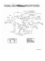
1
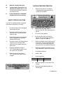
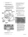
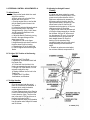
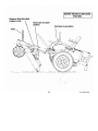
TABLE OF CONTENTS
I. OWNER INFORMATION
Warranty Information -------------------------------------------- ||
Specifications------------------------------------------------------- |||
II. SAFETY
Accident Patterns ------------------------------------------------------1
Safety Instructions and Recommendation -----------------------1
Safety Interlock Systems ---------------------------------------------3
III. START UP AND OPERATION
Checklist Before Operation -------------------------------------------3
Control Locations-----------------------------------------------------------4
Operation ----------------------------------------------------------------- 4
Mowing Recommendations------------------------------------------- 6
VI. MAINTENANCE
Maintenance Schedule ------------------------------------------------6
Maintenance Instructions -------------------------------------------- 7
Leveling the Deck-------------------------------------------------------10
Raising and Lowering Deck for Servicing ------------------------11
Trouble Shooting Checklist ------------------------------------------13
Wiring Schematic--------------------------------------------------------15
P-11408 (2/99)
DIXON LIMITED WARRANTY POLICY - HYDRO-GEAR MODELS
WARRANTY: Dixon Commercial Warranty term is for a period of one (1) year from date of purchase or 400 hours of use, whichever
occurs first. Mowers used for residential homeowner applications (used only at owner's primary place of residence) are warranted for
two (2) years from date of purchase or 400 hours of use, whichever occurs first. DIXON ZTR MOWERS ARE WARRANTED AGAINST
DEFECTS IN MATERIALS AND WORKMANSHIP AND PROVIDES FOR REPLACEMENT OR REPAIR OF PARTS INCLUDING
LABOR COSTS. THIS WARRANTY IS SUBJECT TO THE FOLLOWING CONDITIONS AND LIMITATIONS:
1.
Warranty applies only to original retail purchaser of new and unused mower and accessories.
2.
All Dixon warranty must be accomplished by authorized Dixon dealers and in accordance with Dixon warranty policy and
allowances. All warranty claims must be approved by Dixon Industries, Inc.
3.
Battery warranty. Limited to 90 days from date of purchase.
4.
Accessories Warranty (Grass Catchers, Snow Blades, Tie Rakes, Covers, etc.): Limited to 90 days from date of purchase.
5.
Warranty does not apply to damage in transit or incidents of misuse, negligence, accidents, or alteration. The use of parts or
components other than those supplied by Dixon Industries, Inc. VOIDS ALL WARRANTY.
6.
The following items are not covered by this warranty policy:
(a) Pick up and delivery charges for transportation of mower to and from an Authorized Dixon Dealer's place of business.
(b) Routine maintenance or adjustments.
(c) Belts / chains / sprockets / cutting blades.
(d) Engines - All engines used on Dixon ZTR mowers are warranted by each individual engine manufacturer.
(e) Any cost or expense of providing substitute equipment while repair work is being performed on a warranted mower.
7.
There is no other express warranty. Implied warranties, including those of merchantability and fitness for a particular
/
purpose, are limited to the dame duration of the express warranty, and to the extent permitted by law and all implied
warranties are excluded. Liabilities for consequential damages under any and all warranties are excluded.
WARRANTY VALIDATION: At the time of sale, selling dealer must review each portion of this warranty document, complete the
information section below, secure customer's signature and send copy to Dixon Industries, Inc.
SEE DEALER FOR DETAILS
n
P-11408 (2/99)
SAFETY INSTRUCTIONS AND
RECOMMENDATIONS
ACCIDENT PATTERNS TO AVOID
I.
II.
III.
IV.
V.
CONTACT WITH THE ROTATING
BLADE -- This accident usually
happens when the operator is clearing
the discharge chute of grass, (especially
when the grass is wet), or when the
operator adjusts the machine without
turning it off and waiting for the blades
to completely stop.
1.
with the Zero Turning Radius Mower
should be trained in its proper use and
warned of its dangers. Before operating,
adjusting, or servicing the Zero Turning
Radius Mower they should read and
understand this entire manual and the
engine owner's manual.
PROPELLED OBJECTS - Sticks,
rocks, wires, and other objects can be
propelled out through the discharge chute or
from under the mower housing. Bystanders
are particularly vulnerable.
GRASS CATCHER OR GUARD - The
mower shall not be operated without either
the entire grass catcher or guard in place.
2.
3.
OVERTURNING - This happens when riding
mowers are used on steep slopes,
embankments or hills. The operator in
these cases can come in contact with the
blades or sustain injuries during a fall.
MOWER RUNNING OVER THE
VICTIM ~ This usually happens when a
riding mower is driven in reverse. The
accident victims are most often young
children whom, unseen by the operator of
the mower, were in the area being mowed.
PEOPLE WHO OPERATE, SERVICE,
OR ARE OTHERWISE ASSOCIATED
AVOID CONTACT WITH MOVING
PARTS. Keep hands and feet from
under mowing deck and away from
blades at all times. Turn engine (motor)
off if you must unclog the chute.
AVOID HILLS AND SLOPES. Use
.extreme caution when mowing up or
down slopes. NEVER mow across the
face of a slope. If a slope must be
ascended, back up the slope; drive
forward when descending. Reduce ~
speed and use caution to start, stop and
maneuver. To prevent loss of control on a
slope avoid sharp turns, sudden changes
in direction, and sudden stops and starts.
4.
DISENGAGE POWER TO MOWER
BEFORE BACKING UP. Do not mow
in reverse unless ABSOLUTELY
necessary and then only after turning
around and observing the entire area
behind the mower. Go slowly. Most
"running over victim" accidents occur in
reverse.
5.
BEGINNING OPERATORS SHOULD
LEARN HOW TO STEER the Zero
Turning Radius Mower before
attempting to mow. Start with slow
engine speed and drive without the
blades engaged in an open area until
comfortable with the machine.
"6.
KNOW HOW TO STOP QUICKLY.
Know the location and operation of
every control, especially how to brake
and how to disengage the mower
blades.
P-11408 (2/99)
7.
DO NOT MOVE STEERING CONTROL
LEVERS from forward position to
reverse position rapidly. The speed
and/or direction of travel is affected
instantly by movement of the Steering
Control Levers.
8.
DO NOT ALLOW CHILDREN TO
OPERATE MOWER. Do not allow
others who have not had instruction to
operate mower.
9.
ALWAYS TURN ENGINE OFF AND
10.
several minutes after running. Always
make sure the gas cap is in place.
REMOVE KEY before leaving the mower to
prevent children and inexperienced operators
from starting the engine. Never leave the
mower unattended with engine running.
Always wait for all moving parts and all sounds
to stop before leaving operator's seat.
11.
NEVER CARRY PASSENGERS.
12.
KNOW THE AREA YOU ARE TO
MOW. Watch for hidden danger such as rocks,
roots, sticks, holes, bumps, and drop-offs, etc.
Before mowing, pick up all debris in area to be
mowed. Sharp and hard objects can be
propelled at a high speed and can act like
shrapnel. Walk through tall grass BEFORE
MOWING to make sure there are no hidden
dangers. Mow higher than desired in tall grass
to expose any hidden objects and/or
obstacles, clean the area, and then mow to the
desired height.
NEVER REFUEL A MOWER
INDOORS. Allow the engine time to cool
before refueling. Unseen vapors may be
ignited by a spark. Always clean up spilled
gasoline. Never run the engine indoors in a
garage or any other closed building. Allow
engine to cool before storing in any enclosure.
The engine exhaust and gasoline fumes are
dangerous.
14.
DO NOT SMOKE AROUND THE MOWER
or the gasoline storage container. Gasoline
fumes can easily ignite.
16.
KEEP GASOLINE IN A WELLVENTILATED AREA away from your living
quarters and in tightly-capped safety cans.
Never store mower with gasoline in the tank
inside a building where fumes may reach
open flame or spark.
17.
DISENGAGE BLADES, STOP ENGINE
AND REMOVE IGNITION KEY before any
servicing. Be sure all moving parts and all
sounds have stopped. Let engine cool and
disconnect the spark plugs so the engine
cannot start by accident. A SLIGHT
ROTATION OF THE BLADES COULD
START THE ENGINE.
18.
KEEP ALL NUTS, BOLTS, AND
SCREWS TIGHT to be sure equipment is
in safe working condition, especially blade
mounting bolts.
19.
VEHICLE SHOULD BE STOPPED
WEAR STURDY, ROUGH-SOLED
WORK SHOES AND CLOSE-FITTING
SLACKS AND SHIRTS. Never operate
mower in bare feet, sandals or sneakers.
13.
15.
AND INSPECTED FOR DAMAGE after
striking a foreign object and the damage
should be repaired before restarting and
operating the equipment. Stop immediately
and check for damage or loose parts if
mower should start vibrating.
20.
projecting objects.
21
22.
23.
NEVER REMOVE THE FUEL CAP or
DISENGAGE BLADES BEFORE
DRIVING ACROSS WALKS or
KEEP SAFETY DEVICES AND
GUARDS IN PLACE. If any of the safety
switches become inoperable, have them
repaired immediately.
DO NOT STEP OR STAND ON THE
MOWER HOUSING. Stop or stand only on
the foot deck.
WATCH OUT FOR TRAFFIC near
roadways and when crossing roads.
add gasoline to a running or hot engine that
has not been allowed to cool for
24.
2
DO NOT USE MOWER WHEN GRASS IS
WET OR SLIPPERY.
P-11408 (2/99)
25.
MOW ONLY DURING DAYLIGHT.
26.
THIS MACHINE IS NOT MEANT FOR
HIGHWAY OR STREET USE. It is not
CHECKLIST BEFORE OPERATION
a recreational vehicle and it should not
be operated as such.
27.
1.
Make sure fuel tank is full. Use regular
unleaded gasoline (see engine owner's
manual for more details).
ALWAYS DISENGAGE THE MOWER
BLADE CLUTCH when transporting.
SAFETY INTERLOCK SYSTEM
Your Zero Turning Radius Mower is equipped
with switches interlocked for your safety.
1.
The mower blades must be disengaged
before engine will start.
2.
2.
The Steering Control Levers must be in
the neutral "OUT" position before the
engine will start.
Make sure dirt and foreign matter is
kept out of gas tank. Use a clean funnel and
gas can.
3.
Do not mix oil with gasoline.
3.
The engine will stop if the mower blade
clutch is engaged when the operator
leaves the driver's seat.
4.
Do not use white, high test or premium
gasoline. Do not use de-icers, carburetor
cleaners, or other such additives.
4.
The engine will stop if the Steering Control
Levers are not in the neutral "OUT"
position when the operator leaves the
driver's seat.
5.
Check the crankcase oil level. Make sure the
engine is off. The mower should be parked
on a level area. Do not overfill. (See your
engine manual for more detailed instruction.)
5.
The engine will stop if the brake is
"SET" and the Steering Control Levers
are moved to the "IN" position.
6.
Check the hydrostatic transmission oil level.
(See "Maintenance" section of this manual.)
7.
Check battery fluid level.
The engine will stop if the brake is
"SET" and the mower blade clutch is
engaged.
8.
Inspect V-belts.
9.
Check tire pressure:
6.
Model
All Models
3
Front tires
12psi
Rear tires
12psi
10.
Make sure underside of mower deck is free
of grass.
11.
Make sure mower blades are sharp and
secured tightly.
P-11408 (2/99)
12.
13.
Clean the air intake screen on the
engine if necessary.
3.
Perform any other maintenance as it
becomes necessary. (See the
"Maintenance" section of this manual.)
4.
IMPORTANT: Before cutting grass, clutch must be
broken-in as follows: With engine at full
RPM engage deck until blades come to full
speed and then disengage until blades
come to a complete stop. Repeat 10 times
to seat clutch properly.
DISENGAGE MOWER BLADE CLUTCH by
moving clutch switch to "OFF" position.
PULL ENGINE CHOKE CONTROL to full
position for cold starts.
5.
SET ENGINE THROTTLE TO 1/2
THROTTLE.
6.
TURN IGNITION KEY to "START' position and
release to "RUN" as soon as engine starts.
NOTE: Prolonged cranking will damage
starter motor and shorten the battery life.
7.
ADJUST ENGINE THROTTLE AND
CHOKE for desired engine smoothness and
speed.
NOTE: When mowing, always run engine at
full throttle.
8. RELEASE PARKING BRAKE. Push brake
lever down to release.
10.
TO DRIVE: Move the Steering Control
Levers to the "IN" position. Move the
Steering Control Levers forward to move
forward. Increasing forward movement of
the Steering Control Levers will increase
the speed of travel. To reverse the
direction, pull the Steering Control Levers
slightly back. To turn, move one Steering
Control Lever slightly ahead of the other.
To turn on a zero radius axis, go slowly
and move one Steering Control Lever
forward and one Steering Control lever
rearward. (For a right hand turn the left
hand Steering Control lever will be ahead
of the right hand Steering Control. For a
left hand turn the right hand Steering
control will be ahead of the left hand
Steering Control.)
OPERATION
1. MOVE STEERING CONTROL LEVERS TO
neutral "OUT position.
2.
SET PARKING BRAKE. Pull up to set.
4
P-11408 (2/99)
D. Slow engine speed with throttle to
slowest position.
E. Turn ignition key to "OFF" (left)
position.
F. Remove the key and wait for all
movement and all sound to cease
before dismounting.
11.
BRAKING: To brake mower, gently
move the Steering Control Levers in the
direction opposite to travel. If the parking
brake is engaged with the Steering Control
Levers in the "IN" position the engine will
stop.
12.
CUTTING HEIGHT ADJUSTMENT: With
the Cut Height Adjustment Lever latched
into the top cut height latch. Insert Cut
Height Stop Pin to desired cutting height.
Pull Cut Height Adjustment Lever
rearward and then to the right to clear top
cut height latch. Lower Cut Height
Adjustment Lever until it rests on Cut
Height Stop Pin.
13.
ENGAGE MOWER BLADE CLUTCH:
14.
TO STOP:
A. Move Steering Control Levers to neutral
position and then to the "OUT" position.
15.
TO FREE WHEEL MACHINE: UNLOCK
TRANSMISSION: The transmission release levers
are located on each side of the mower behind the
rear drive axles and below the engine mounting
plate. Lift the levers slightly, push them forward
and then down to release the transmissions for
free wheeling. To engage the transmissions lift
the levers slightly, pull them to the rear and then
down. NOTE: The tractor should never be pulled
at more than 2 miles per hour or for any
appreciable distance.
Set the Blade Clutch Switch to the "ON"
position. The engine will not start if the
blade clutch is engaged. If the operator is
not in the seat, the engine will stop if the
clutch is engaged.
B. Disengage the mower blade clutch
by moving the clutch to the "OFF"
position.
C. Set the parking brake.'"
5
P-11408 (2/99)
MOWING RECOMMENDATIONS
1.
Keep mower blades sharp.
2.
Make sure deck and discharge are
clean.
3.
When mowing tall grass, make two
passes, mowing off 1/2 of the desired cut
on the first pass, and then the desired
height the second pass. Check for hidden
dangers first.
4.
Go slowly for trimming.
5.
Always cut grass with the engine at full
throttle speed. This "ENGINE" speed
allows the cutting blades to operate at
optimum cutting speed. Control
"GROUND" speed with the Steering
Control Levers.
6.
Vary ground speed to suit conditions
(i.e. go slower in tall thick grass, on hills,
wet conditions, etc.).
Replace decals when illegible. Write factory for free replacement.
MAINTENANCE SCHEDULE
,
SERVICE
WHEN
Check crankcase oil level ————————————————————————-- before each use
Clean grass from Hydrostat fans and cooling fans ———————————---— before each use
Check air intake screen ——————————————————————----——— after each use
Clean grass under deck ————————————————————————---— after each use
Check tire pressure ———————————————————————————— every 10 hours
Check battery fluid ———————————————————-——-———————every 10 hours Sharpen
mower blades ——————————————————————————--------—— every 10 hours
Clean air filter pre-cleaner element ———————————————------——— every 25 hours
Check Hydrostatic transmission fluid ———————————————————— every 25 hours
Check drive belts ————————————————————————————— every 50 hours
(20 hours break-in)
Service Air Cleaner Filter Element ——————————————————— every 100 hours
Change engine crankcase oil ———————————————————————1QC hours
oil filter ———————————————————----------—————— 200 hours
Change Hydrostat oil and oil filter ————————————————————— every 500 hours
(100 hours break-in)
Replace air filter element ———————————————————————------— annually or 500 hours
Check spark plugs ———————————————————————————— annually or 5 00 hours
Service battery ——————————————————————————------——— annually or 500 hours
6
P-11408 (2/99)
MAINTENANCE INSTRUCTIONS
1.
ENGINE:
3.
Correct tire pressure is essential for
efficient operation of the mower. Check tire
pressure as requested in the maintenance
schedule. Inflate tires to the pressures
listed below:
For complete maintenance and operating
information for your engine, please refer to
your engine operating and maintenance
instructions furnished by the engine
manufacturer and included in your Dixon
Zero Turning Radius Mower information
packet.
NOTE: Air intake screen must be kept
clean. If plugged, engine may be seriously
damaged by over heating.
2.
TIRES:
Lug nuts should be checked regularly for
tightness.
BATTERY:
~*.
MOWER BLADES:
Check sharpness of mower blades after
every 10 hours of operation. To sharpen
blades proceed as follows:
Keep the electrolyte level above the plates
in each cell by adding distilled water as it
becomes necessary. Add water just before
operating the mower to mix the water with
the solution. Be careful not to overfill the
battery - the electrolyte solution is corrosive
and can cause damage to surrounding
metal parts if it should spill. When taking
the battery out of the mower for servicing,
make sure to connect the cables to the
battery exactly as they were prior to
removal. Always disconnect the ground (-)
wire first and always reconnect the ground
(-) wire last.
A. Remove bolt, lockwasher, and cup
washer mounting blade on shaft. Remove
blade.
B. Blades should be discarded when worn
excessively.
Keep the battery clean. Remove the
corrosion around the battery terminals by
applying a solution of one part baking soda
to four parts water. Coat all exposed
terminal surfaces with a light layer of
grease or petroleum jelly to prevent
corrosion.
NOTE:
At temperatures below 32 degrees F
(0 degrees C) the full charge state
must be maintained to prevent cell
electrolyte from freezing and causing
permanent battery damage.
C. Sharpen blades with a hand file,
electric grinder or blade sharpener. Wear
gloves and eye protection when
sharpening. Grind blade at original 25
degree bevel.
7
P-11408 (2/99)
D. Check balance of blade by positioning
the blade on a nail or blade balance
pedestal. Grind the blade on the end that
is heavier until both sides balance.
Check the oil level in hydrostatic
transmission oil reservoir after every 25
hours of usage. Clean the oil reservoir
cap and the area around it prior to
removal. Check the oil level on the
dipstick. The proper oil level should
register between the marked hole on the
dipstick and the end of the dipstick.
Replenish as needed with 20W-50 Motor
Oil. DO NOT OVER FILL. When
checking the oil level, be very careful to
keep the reservoir clean
E. Install blade, cup washer, lockwasher,
and bolt. Make sure to tighten bolt to 60
ft.lbs.
5.
V-BELTS:
There are 3 V-belts on your Dixon Zero
Turning Radius Mower. They should be
checked every 50 hours. Replace any
belts found to be in poor condition. All
belts are equipped with spring loaded belt
tighteners and do not require tightening
adjustments.
6.
Change the oil in the reservoir and
hydrostatic transmission filter after the
first 100 hours of use, then every 500
hours after that. Remove the filter and be
sure all oil has drained from the reservoir.
Replace with new filter (P/N 7252) and
20W-50 Motor Oil.
LUBRICATION:
A. Engine: Follow engine
manufacturer's recommendation.
B. Deck Spindles: Lubricate with 3
"shots" only, every 100 hours.
C. Hydrostatic Transmission & Filter:
Follow instructions listed below.
7. PARKING BRAKE ADJUSTMENT:
8
A. With the brake handle in the
"RELEASE" position and the actuating
lever against the stop, remove the cotter
pin from the castle nut. Insert a 0.010
feeler gauge between the brake disc and
the brake puck. Tighten the castle nut
with the feeler gauge inserted until the
gauge fits snugly«between the disc and
puck. The gap should not be so tight that
the feeler gauge cannot be reinserted
after removal. Back the castle nut to the
closest pin hole and reinsert the cotter pin.
P-11408 (2/99)
D. Adjusting for Straight Forward
Tracking:
8. STEERING CONTROL ADJUSTMENTS A.
To Adjust Neutral:
a. Remove the fender skirts from each
side of the machine.
b. Block up the unit so that the Drive
Wheels are off the ground.
c. Start the engine and run at a fast idle
with the Steering control levers in the
"out" position.
d. Loosen the locknuts tightened against
the rod end ball joints in the Upper
Linkage Assembly. (Note: One of these
is a left hand nut and will have to be
turned backwards.)
e. Adjust the Neutral Position by turning
the rod in the upper linkage until the
wheel stops turning.
f. Retighten the nuts on the Upper
Linkage Assembly and check to see that
the drive wheel is still not turning.
g. Repeat steps 1-6 for the other side.
h. Shut off engine before removing the
blocks.
In a large open area, actuate the control
handles into the full forward position. If the
mower veers in either direction Left for
Right some adjustment is necessary. a. If
the mower veers to the right, then the
right hydrostat needs to be sped up. If the
mower veers to the left, then the left
hydrostat need to be sped up. b. Stop the
machine and shut off the engine.
c. Slightly loosen the bolt at the lower end
of the upper linkage assembly on the side
that is slower. Using a 1/8" alien wrench
turn the setscrew 1/4 turn in. It may take
several test drives to get the mower to
track straight forward. d. Once the
tracking is to the operators liking,
completely tighten the bolt on the control
linkage assembly that was loosened
earlier.
e'. Recheck to make sure neutral adjust
has not been effected, see procedure A.
B. To Adjust "IN" Position of the Steering
Controls:
a. Remove the 2 Front Bolts,
Lockwashers, and Washers which hold
the Fender Cap.
b. Pull the boot from the hole in the
fender cap, exposing the cast iron lever.
c. Using a 5/32° Alien Wrench, turn the
setscrew to adjust the stop.
d. Replace the Boot into the hole in the
Fender Cap.
c. Replace the 2 Front Bolts,
Lockwashers, and Washers.
C. To Align Handles:
Sit on the seat and push the control
levers full forward and full backward. If
the ends do not match the handles
maybe adjusted as follows:
a. Locate Setscrew stops in the Steering
Control Lever Base which stop the lever
in each direction. (Note: The one at the
rear is the stop for FWD and the one in
the front is the stop for REV.)
b.-Adjust setscrew stops so that handles
line-up together when shifted full forward
and full reverse.
*'
9
P-11408 (2/99)
9.
HYDROSTATIC TRANSMISSIONS:
11.
Before each use, check to be sure that the
cooling fins of the hydrostatic
transmissions are clean. Excessive
accumulation of oil, dirt, or trash may
cause the transmissions to overheat.
NEVER WASH ACROSS TOP OF
RESERVOIR with water or steam. Fill
reservoir as required per the maintenance
schedule listed in this book.
10.
LEVELING THE DECK:
A. Set the tire pressure on all four tires
B. Move the tractor to a hard, level
surface (i.e. Concrete or blacktop).
Place a 2 x 4 board under all four
comers of the deck shell, just inside
of the anti-scalping wheels. Lower
the deck down onto the boards. The
deck must rest on the boards, NOT
the anti-scalping wheels.. Adjust the
deck hangers longer or shorter until
the deck "just" comes off of the
boards. Remove the boards and
verify that the deck is hanging on all
four deck hangers, re-adjust if
necessary. Lock the jam nuts on the
two front deck hangers. (NOTE: the
two rear deck hangers will be easier
to adjust if the fender skirts are
removed).
HYDROSTAT DRIVE BELT
REPLACEMENT PROCEDURE:
(The hydrostatic drive is equipped with an
automatic, anti-backlash belt take-up)
A. Remove the 3/8° bolt lockwasher,
heavy washer, and spring, from the rear
of the assembly.
B. Squeeze the clamp latch to release the
clamp, allowing the idler arm/pulley to
swing forward towards the front of the
mower. Remove old belt if required.
Replace with new belt. C. With the belt in
place on all pullies reinsert the spring,
heavy washer, lockwasher, and 3/8° bolt.
Tighten 3/8" bolt fully.
10
P-11408 (2/99)
PROCEDURE FOR RAISING AND
LOWERING THE DECK FOR
SERVICING
12. RAISING THE DECK:
A. Remove cut height adjustment pin and
completely lower the cut height adjustment
lever. Re-insert the cut height adjustment
pin into the 3-1/2° cut height position (this
will lock the cut height adjustment lever into
the lowest position).
. B. Flip up the foot deck to allow access to the
engine to deck drive belt. Roll the engine to
deck drive belt off the center spindle. Hook
the engine to deck drive belt onto the bolt
protruding out of the top of the foot deck
support angle.
C. Lift the rear corner of the deck and
disconnect the rear deck mounting
latch. Repeat for the other side.
D. Position the front caster wheels so they are
away from the deck (such as the tractor
would be traveling in reverse).
E. Attach a hoist to the deck lift bolt. Lift the
nose of the deck until the deck is standing
vertical and the deck latch engages.
IMPORTANT NOTE: MAKE SURE
THAT THE DECK IS LIFTED FAR
ENOUGH FOR THE DECK LATCH TO
FULLY ENGAGE THE LOCKING
PIN (located on the left side of the deck
mounting suspension). This will prevent
the deck from falling down when
servicing the underside of the mower
deck.
13. LOWERING THE DECK:
A. While lifting the nose of the deck disengage the
deck latch from the locking pin. Push
the bottom of the deck towards the rear of the
tractor while holding the deck latch so that it
clears the locking pin. Lower the deck until it
rest on the ground.
-B. Lift the rear comer of the deck and re connect the rear deck mounting latch.
Repeat for the other side.
C. Roll the engine to deck drive belt back onto the
center spindle. Insure that the engine to deck
drive belt is installed onto all of the pullies and
idlers in the drive train.
D. Lower the foot deck down into the operation
position.
12
P-11408 (2/99)
- . . . .
.
'
TROUBLE SHOOTING CHECK LIST
1.
ENGINE WONT TURN OVER:
2.
ENGINE WILL TURN OVER BUT WONT START:
3.
HARD TO START ENGINE:
4.
ENGINE STARTS BUT CUTS OUT:
5.
ENGINE KNOCKS:
Mower blades engaged ——---------————————————————— disengage blades
Drive not in neutral ----------— move Steering Control Levers to neutral "OUT" position
Blown fuse ———————————--------————————————————— replace fuse
Dead battery ———————---------————————————————— charge or replace
Solenoid ———————————————————————————— consult dealer
Ignition switch —----------—-—————————————————————— consult dealer
Starter ————————--------————————————————————- consult dealer
No gas ————————————-------—————-——————————-——— refuel
clean or replace fuel filters
Over or under choked ——————--------———————————————— adjust choke
Spark plug not firing —————————-------———————————— check spark plug
condition and reset gap*
Carburetor maladjustment ———————------————— reset carburetor adjustment*
Ignition switch ————————————————-------——--—————— consult dealer
Fuel line clogged ———————————-— clean fuel line and check fuel filter Faulty
fuel pump ———————————————————————— consult dealer Spark plug
wire loose or grounded —————————— check spark plug wires Spark plug(s)
faulty or improperly gapped ————————-------------------------—— check spark plug
condition and reset gap*
Electronic ignition defective —————————————————— consult dealer Dirty
or maladjusted carburetor —————————————--------------— readjust carburetor*
consult dealer for carburetor service
Water in gasoline —————— drain old gasoline and replace with new gasoline
clean carburetor bowl
Clogged fuel line ——————————————————————— check fuel filter
clean fuel line
Vent in fuel cap plugged —————————————————————— check vent
Faulty fuel pump ———————————————————————— consult dealer
Maladjusted carburetor ————————————————---—— readjust carburetor*
Engine dies when Steering Control Levers are moved "IN" — parking brake set
release brake
Low oil level ————————————---------------———-—-—-—— check and add oil
Ignition timing off ———————————-----------—————————— consult dealer
fuel octane too low ———————————-------——————— drain and replace with
higher octane gasoline
Overheated engine ---—————————----------—— shut off engine and allow to cool
* See engine manual for engine adjustments.
13
P-11408 (2/99)
6.
ENGINE SOMETIMES SKIPS AT HIGHER SPEEDS:
7.
ENGINE OVER HEATED:
8.
9.
Incorrect Ignition Timing —————————----—————————— consult dealer
Carburetor maladjusted ——————————————--———— readjust carburetor
Faulty spark plugs ——————————————————-------———— check spark plug
condition and reset gap*
Bouncing off seat safety switch ———————------——— slow down on rough terrain
Air intake screen or fins clogged ————————— clean intake screen and fins Fuel
mixture too lean ——————————————————— readjust carburetor* Oil level
too low or too high —————————————————— adjust oil level Improper
ignition timing ———————————————————— consult dealer Running
engine too slow ——————————--------------------———————— run engine faster
(NOTE: Always mow at full throttle setting.)
,
ENGINE IDLES POORLY:
Carburetor maladjustment ————————————————— readjust carburetor
Improper spark plug gap —————--------—————————— check and re-gap plug*
ENGINE BACKFIRES:
Carburetor maladjustment ———————————————— readjust carburetor*
10.
ENGINE RUNS BUT MOWER WONT MOVE FORWARD:
11.
MOWER LOSES POWER OR TRANSMISSIONS OVER HEATS:
12.
ENGINE STALLS WHEN BLADES ARE ENGAGED:
14
Drive belt broken or slipping ———————————————— replace drive belt Shift
linkage cable disconnected —————————-------------————————— reconnect
Transmission shift arm disconnected —————------——————————— reconnect
Transmission oil low —————-———------—————————— add oil
Transmission locks in free wheel position ——— put in lock position (see pg. 5)
Hydrostat oil filter plugged ———————————————————— replace filter Bad
transmission ———————————————————————— consult dealer Gear
mating transmission/gearbox disconnected —————-------------——— consult dealer
Hydrostat transmission oil too low or too high ————————————— add oil
OR drain oil as needed
Transmission damage ————————————————————— consult dealer
Transmission blowing oil out cap —————————————— overfilled or water
contaminated
Operator not on seat ———————————————————————— sit on seat Faulty
interlock system ————————————————————— consult dealer Bad blade
spindle bearing —————————————————— consult dealer Deck drive belt
not properly routed —————————————————— reroute Blades blocked by
foreign material ————————---------------------------------————— clean under deck
* See engine manual for engine adjustments.
P-11408 (2/99)
15
P-11408 (2/99)
NOTES:
WARNING The Engine Exhaust from this product contains chemicals known to the
state of California to cause cancer, birth defects or other reproductive
harm.
®Dixon and ZTR are registered trademarks of Dixon Industries, Inc.
Dixon Industries, inc.
A BLOUNT International, Inc. company
P.O. Box 1569
Coffeyville KS 67337 0945
316 251 2000
P-11408
February 1999