1
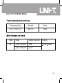
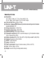
Model UT713
OPERATING MANUAL
Model UT713: OPERATING MANUAL
TABLE OF CONTENTS
TITLE
Introduction
Unpacking Inspection
Safety Information
Turning the Calibrator On
Simulating a Thermocouple
Measuring a Thermocouple
Simulating TC or Source mV
Measure TC or mV
Cold Terminal Temperature Autocompensation
Explanation of International Symbols
Maintenance
Specifications
Temperature Measure and Thermocouple Simulate
PAGE
3
3
4
6
6
7
8
10
12
14
15
19
19
1
Model UT713: OPERATING MANUAL
TABLE OF CONTENTS
TITLE
Thermocouple Standards and Scales
Millivolt Measure and Source
General Specifications
2
PAGE
21
21
22
Model UT713: OPERATING MANUAL
Introduction
The UNI-T Model UT713 Thermocouple Calibrator is a precise source and measurement
tool for calibrating thermocouple instruments. The calibrator sources or measures
mV or 8 different type of TC in units of , . But the Meter cannot uses as an output
source and measurement.
Unpacking Inspection
Open the package case and take out the Meter, check the following items carefully
to see any missing or damaged parts:
Item
1
2
3
4
Description
Operating Manual
Test Lead
Alligator Clip
9V Alkaline Battery (1604A or 6LF22)
Qty
1 piece
1 pair
1 pair
1 piece
3
Model UT713: OPERATING MANUAL
Safety Information
This Meter complies with the standard CE EN61326.
Use the Meter only as specified in this operating manual, otherwise the protection
provided by the Meter may be impaired.
Warning
To avoid possible electric shock or personal injury:
l Before using the calibrator inspect the case. Do not use the calibrator
if it is damaged or the case (or part of the case) is removed. Look for
cracks or missing plastic.
l During measurement, do not contact the naked wire, connector, unused
terminal or the circuit under test.
l Inspect the test leads for damaged insulation or exposed metal. Replace
damaged test leads with identical model number or electrical
specifications before using the Meter.
l When using the test leads, keep your fingers behind the finger guards.
l Never apply more than 30V between any two terminals, or between any
terminal and earth ground.
4
Model UT713: OPERATING MANUAL
l Replace the battery as soon as the battery indicator appears. With a
low battery, the Meter might produce false readings that can lead to
electric shock and personal injury.
l The internal circuit of the calibrator shall not be altered at will to avoid
damage of the calibrator and any accident
l Do not use or store the calibrator in an environment of high temperature,
humidity, explosive, inflammable and strong magnetic field. The
performance of the Meter may deteriorate after dampened
l Under the influence of Radiated, Radio-Frequency Electromagnetic Field
phenomenon, the captioned model may malfunction and can self-recover
after the test.
l When servicing the Meter, use only the same model number or identical
electrical specifications replacement part.
l Constantly check the battery as it may lead when it has been using for
some time, replace the battery as soon as leaking appears. A leaking
battery will damage the calibrator.
l Take out the battery when not using for a long time.
5
Model UT713: OPERATING MANUAL
Turning the Calibrator On
Press
to turn the calibrator on and off
Output
Show TC type or
voltage range
selected
Press to toggle
or
Press so that
OUTPUT is on
the display
Press TYPE to
select TC type or
DC mV
Press to turn
the Meter on
and off
Press and to
increment or
decrement a digit.
Press and to step
up/down from 0 to 9 .
Hold down to scroll
faster
6
Press to toggle
positive or
negative
temperature
Output Terminals
Figure 1
Model UT713: OPERATING MANUAL
Input
Show TC type or
voltage range
elected
Display the
selected
or
Press so that
INPUT is on the
display
Press to toggle
or
Press to turn the
Meter on and off
Press Type to
select TC type or
DC mV
Input Terminals
Figure 2
7
Model UT713: OPERATING MANUAL
1. Press the
pushbutton to turn the Calibrator on.
2. Press OUTPUT to display OUTPUT if the Calibrator is at input mode which displays
INPUT.
3. Press
to select the requested TC type or DC mV range.
4. Press or to increment or decrement a digit.
5. Press or to step up or down from 0 to 9. Hold down to scroll faster.
6. Insert the test leads to the OUPUT terminals as figure 3.
7. Connect the other end of the test leads to the TC measurement equipment or the
DC mV measurement equipment.
Note:
When connecting the calibrator to the auto ranging DC mV measurement equipment
or TC measurement equipment, it must lock the range.
8
Model UT713: OPERATING MANUAL
Measurement
equipment
Figure 3
9
Model UT713: OPERATING MANUAL
1. Press the
pushbutton to turn the Calibrator on.
2. Press INPUT to display INPUT if the Calibrator is at output mode which displays
OUTPUT.
3. Press
to select the requested TC type or DC mV range.
4. Insert the test leads to the INPUT terminals as figure 4.
5. Connect the other end of the test leads to the TC simulate equipment or the DC
mV source equipment.
Note:
Measuring TC must select the corresponding TC type.
When measuring DC mV, the input voltage must not exceed the present range of
the Calibrator.
When using the TC cable with standard plug to measure temperature, it is necessary
to add an adaptor.
10
Model UT713: OPERATING MANUAL
Output
equipment
Figure 4
11
Model UT713: OPERATING MANUAL
Follow the below procedure to start the cold terminal temperature auto compensation
functions:
1. Press the
pushbutton to turn the Calibrator on.
2. Press INPUT to display enter INPUT mode
3. Press
to select J type.
4. Press and hold
and
together to display 0 or 1 (display 0 is cold terminal
temperature auto compensation, display 1 is the remove cold terminal
temperature auto compensation), release the two buttons.
5. Press and to adjust the digit to 0, press
to confirm.
6. Press
pushbutton to turn the Calibrator off.
7. The setting is finished.
8. At that moment
At simulate TC mode:
The calibrator output thermoelectric force = the corresponding thermoelectric
force of the set temperature minus the corresponding thermoelectric force of
the room temperature.
At Measure TC mode:
The Calibrator display temperature = The corresponding temperature of the
Calibrator input terminal thermoelectric force plus room temperature.
12
Model UT713: OPERATING MANUAL
Note:
Because the temperature transducer aluminum plate is put at the back of the
Calibrator, try to open the tilt stand if possible when operating the Calibrator.
Don’t touch the aluminum plate when operating the Calibrator to ensure the
accurate of compensation temperature.
If the operating temperature is changed, it is necessary to wait for around 10
minutes to stable the internal transducer before operating the Calibrator.
Follow the above 1 to 7 steps to remove the cold terminal temperature auto
compensation, but change the adjust digit to 1 on step 4.
13
Model UT713: OPERATING MANUAL
Explanation of International Symbols
The following symbols are used on the calibrator or in this operating manual. The
table below explains their meaning.
International Symbols
Symbol
14
Meaning
Grounding
Warning. Refer to the Operating Manual
Deficiency of Built-In Battery
Double Insulated
Conforms to Standards of European Union
Model UT713: OPERATING MANUAL
Maintenance
Warning
Make sure the calibrator is off and the test leads are removed from the input
terminals and the circuit under test before opening the calibrator’s case.
For maintenance procedures not described in this sheet, contact your dealer.
l Do not store the Meter in an environment of high temperature, humidity and
strong magnetic field.
l Check the battery and test leads. Replace as necessary.
l Review this instruction manual to make sure you are using the calibrator
correctly.
Periodically wipe the case with a damp cloth and detergent;
do not use abrasives or solvents.
15
Model UT713: OPERATING MANUAL
Periodically wipe the case with a damp cloth
and detergent; do not use abrasives or
solvents.
l When the symbol appears on the display,
replace the battery with a 9V alkaline
battery (1604A or 6LF22)
l Remove the battery from the battery door
and turn the calibrator off when it is
not using for a long time.
Figure 5
16
Model UT713: OPERATING MANUAL
Warning
To avoid personal injury or damage to the calibrator, use only a 125mA 250V
fuse for F1.
In Input mode, the calibrator and TC are reliably connected. When the display
continuisly shows OL, the fuses may be blown.
17
Model UT713: OPERATING MANUAL
Replace the fuses using the following procedure:
1. Remove the test leads from the calibrator
terminals and turn the calibrator off.
2. Remove the screw on the battery door, then
remove the battery door and take out the
battery.
3. Remove the three screws from the case bottom
and turn the case over.
4. Gently remove the fuse from its mounting
bracket.
5. Replace the blown fuse with a 125mA 250V
fuse.
6. Fit the top and bottom covers together.
7. Reinstall the three screws.
8. Replace the battery door and reinstall the
battery door screw.
Figure 6
18
Model UT713: OPERATING MANUAL
Specifications
Specifications are based on a one year calibration cycle and apply for ambient
temperature from +18 to +28 unless stated otherwise.
Thermocouple
Type
J
K
T
E
N
Temperature Ranges
-200.0~1200.0
-328.0~2192.0
-200.0~1370.0
-328.0~2498.0
-200.0~400.0
-328.0~752.0
-200.0~950.0
-328.0~1742.0
-200.0~1300.0
-328.0~2372.0
Display
Resolution
0.1
or 0.1
Accuracy
0.04%
( -100
0.04%
( -148
0.04%
( -100
0.04%
( -148
1.5
)
2.7
)
1
)
1.8
)
19
Model UT713: OPERATING MANUAL
Thermocouple
Type
Temperature Ranges
Display
Resolution
-20~1750
R
-4~3182
-4~3182
600~1800
B
20
1112~3272
0.04%
100
0.04%
( 212
0.04%
( 100
0.04%
( 212
(
-20~1750
S
Accuracy
1
or 1
3
)
5.4
)
2
)
3.6
)
Model UT713: OPERATING MANUAL
Thermocouple Type
Standard
Scales
J, K, T, E, N, R, S, B
NIST-175
ITS-90
Mode
Range
Display Resolution
mV
-10.00~110.00mV
10 V
-110.0~1100.0mV
0.1mV
Accuracy
0.04% 2 digits
21
Model UT713: OPERATING MANUAL
Resolution:
TC: 0.1 or 0.1 (J, K, T, E, N); 1 or 1 (R, S, B).
DC mV: 10 V (110mV range); 0.1mV (1100mV range)
Cold Junction Error: 0.5 (-0~50 )
Maximum voltage applied between any terminal and earth ground or between
any two terminals: 30V
Storage temperature: -10 to 55
Operating temperature: -0 to 50
Operating altitude: 3000 meters maximum
Temperature coefficient:0.005% x specified range per for temperature ranges
-0 to 18 and 28 to 50 .
Relative humidity: 95% (0 ~ 30 ), 75% (30 ~40 ) and 45% (40 ~50 )
Vibration:Random 2g, 5Hz to 500Hz.
Shock: 1 meter drop test
Safety: CE EN61326
Power requirements: Single 9V alkaline battery (1604A or 6LF22)
Size: 193mm x 96mm x 47mm
Weight: around 0.45kg (including alkaline battery)
22
Model UT713: OPERATING MANUAL
* END *
This operating manual is subject to change without notice.
23
Model UT713: OPERATING MANUAL
Copyright 2007 Uni-Trend Group Limited.
All rights reserved.
Manufacturer:
Uni-Trend Technology (Dongguan) Limited
Dong Fang Da Dao
Bei Shan Dong Fang Industrial Development District
Hu Men Town, Dongguan City
Guang Dong Province
China
Postal Code: 523 925
Headquarters:
Uni-Trend Group Limited
Rm901, 9/F, Nanyang Plaza
57 Hung To Road Kwun Tong
Kowloon, Hong Kong
Tel: (852) 2950 9168
Fax: (852) 2950 9303
Email: [email protected]
http://www.uni-trend.com
24