1
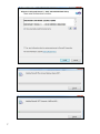
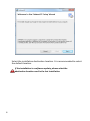
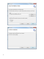
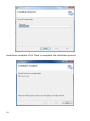
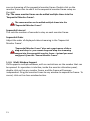
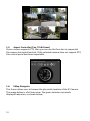
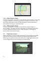
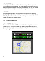
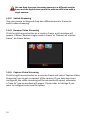
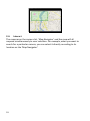
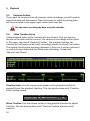
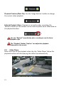
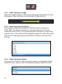
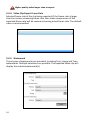
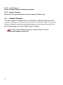
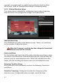
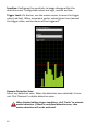
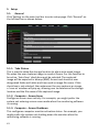
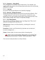
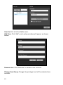
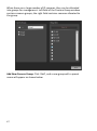
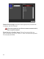
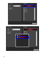
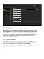
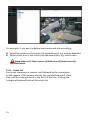
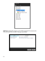
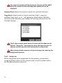
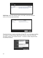
EdiView 32 User Manual 04-2013 / v1. 0 CONTENTS Installation ................................................................................................. 5 1. 2. System Requirements ....................................................................................................................5 Software Installation......................................................................................................................6 EdiView 32 .................................................................................................11 1. Monitoring ...................................................................................................................................11 1-2. Quick Launch Icons ..............................................................................................................11 1-2-1. Full Screen............................................................................................................................11 1-2-2. Monitoring Grid ...................................................................................................................12 2 1-2-3. 1-2-4. 1-3. On-Screen Display (OSD) .....................................................................................................12 Screen Lock ..........................................................................................................................12 Camera List ..........................................................................................................................12 1-3-1. 1-3-2. 1-3-3. 1-3-3. 1-3-4. 1-3-5. 1-3-6. Camera Status ......................................................................................................................13 Menu ....................................................................................................................................14 Add Camera .........................................................................................................................14 Remove Camera...................................................................................................................15 Edit Camera..........................................................................................................................15 Activate/Stop Camera..........................................................................................................16 Manual Recording ................................................................................................................16 1-3-7. 1-3-8. 1-4. 1-4-1. 1-4-2. 1-4-3. 1-4-4. 1-5. 1-6. 1-6-1. 1-6-2. Checklist or Thumbnail Display ............................................................................................16 Show/Hide Camera Information..........................................................................................17 Monitor Layout ....................................................................................................................17 Add/Remove Monitor ..........................................................................................................18 Custom Monitor Frame .......................................................................................................18 Sequential Monitor Frame...................................................................................................19 Multi-Window Support ........................................................................................................21 Aspect Controller (Pan, Tilt & Zoom) ...................................................................................22 EMap Navigator ...................................................................................................................22 EMap Navigator Zoom .........................................................................................................23 EMap Navigator Move .........................................................................................................23 1-7. 1-7-1. 1-7-2. 1-8. 1-8-1. 1-8-2. 1-8-3. Digital Zoom Control ............................................................................................................23 Digital Zoom .........................................................................................................................24 Move ....................................................................................................................................24 Monitor Frame Setup ..........................................................................................................24 Add Video Streaming ...........................................................................................................24 Switch Streaming .................................................................................................................25 Remove Video Streaming ....................................................................................................25 1-8-4. Capture Video Streaming.....................................................................................................25 2. EMap ............................................................................................................................................27 2-1. Add/Remove EMap ..............................................................................................................27 2-2. Using the EMap ....................................................................................................................27 2-2-1. Map Scale.............................................................................................................................27 2-2-2. Move the Map .....................................................................................................................27 2-2-3. Image Preview .....................................................................................................................28 2-2-4. Image Transparency ............................................................................................................28 2-2-5. Remove Camera...................................................................................................................28 2-2-6. Camera Name ......................................................................................................................28 2-3. Map Navigator .....................................................................................................................28 2-4. Interact.................................................................................................................................29 3. Playback .......................................................................................................................................30 3-1. 3-2. 3-3. Retreive Archive...................................................................................................................30 Video Timeline Setup ...........................................................................................................30 Video Player .........................................................................................................................31 3-3-1. 3-3-2. 3-3-3. 3-3-4. 3-4. 3-4-1. 3-4-2. Play Time Scroll Bar .............................................................................................................32 Power Saving Mode .............................................................................................................32 Playback Speed ....................................................................................................................32 Clip Skipping .........................................................................................................................32 Export Video Clip .................................................................................................................32 Video Clip Export Length .....................................................................................................33 Video Clip Export Resolution ...............................................................................................33 3-4-3. Video Clip Export Quality .....................................................................................................33 3-4-4. Video Clip Export Frame Rate ..............................................................................................34 3-4-5. Watermark ...........................................................................................................................34 3-4-6. Audio Export ........................................................................................................................35 3-4-7. Export File Path ....................................................................................................................35 3-5. Multiple Playbacks ...............................................................................................................35 4. Recording .....................................................................................................................................36 4-1. Scheduled Recording ...........................................................................................................36 4-1-1. Select Mode .........................................................................................................................37 4-1-2. Clear Mode ..........................................................................................................................38 4-1-3. Predefined Templates..........................................................................................................38 4-2. Motion Detection Recording ...............................................................................................39 4-2-1. Main Features ......................................................................................................................39 4-2-2. Recording Before Alarm Trigger ..........................................................................................40 4-2-3. Stop Recording After Alarm Trigger.....................................................................................40 4-2-4. Scheduled Setup ..................................................................................................................40 4-2-5. Motion Detection Setup ......................................................................................................41 5. Setup ............................................................................................................................................43 3 4 5-1. 5-1-1. 5-1-2. General ................................................................................................................................43 Take Picture .........................................................................................................................43 Computer – Screen Saver ....................................................................................................43 5-1-3. 5-1-4. 5-1-5. 5-1-6. 5-1-7. 5-1-8. 5-1-9. 5-2. 5-2-1. 5-2-2. Computer – Screen Shutdown .............................................................................................43 Computer – Sleep Mode ......................................................................................................44 Language ..............................................................................................................................44 Account – Change Password................................................................................................44 User Management ...............................................................................................................44 SMTP ....................................................................................................................................46 Camera Groups ....................................................................................................................46 Recording .............................................................................................................................50 Recording Path .....................................................................................................................51 Reserve Available Hard Disk Storage Space ........................................................................51 5-2-3. 5-2-4. 5-3. Preserve Recorded Video ....................................................................................................51 Insufficient Hard Disk Space ................................................................................................51 Screen Setup ........................................................................................................................51 5-3-1. 5-4. 5-4-1. 5-4-2. OSD Setting ..........................................................................................................................52 Events and Actions...............................................................................................................52 Event List ..............................................................................................................................53 Action List ............................................................................................................................55 Installation 1. System Requirements *1 The maximum decode frame rate not considering Ethernet connection speed. Video format: MPEG4, resolution: 640x480, quality: medium/normal Figures above can vary due to difference in video source and system setup. 5 2. Software Installation 6 7 Select the installation destination location. It is recommended to select the default location. If the installation is a software update, please select the destination location used in the last installation. 8 9 Installation complete. Click ‘Close’ to complete the installation process. 10 EdiView 32 1. Monitoring When the program starts up, a window will appear requesting user name and password. The default username is ‘admin’and password is ‘1234’. You should change the password immediately after your first login, please refer to Settings for instructions. Navigate the software using the main menu across the top of the screen, as shown below. Hover your cursur over an icon or menu item to display a tooltip with a brief description. 1-2. Quick Launch Icons There are four quick launch icons displayed in the upper-left corner (Full Screen, Monitoring Grid, On-Screen Display and Lock). The icons are white when inactive and green when active. 1-2-1. Full Screen Click the “Full Screen” icon to enlarge the software window to full screen. Click the icon again or press ESC to exit full screen. 11 1-2-2. Monitoring Grid Click the “Monitoring Grid” icon to toggle the monitoring grid display on/off in the main screen on the right side. Please refer to Settings for different grid colors. 1-2-3. On-Screen Display (OSD) Click the “OSD” icon to toggle the on-screen display on/off in the main screen on the right side. Please refer to Settings for advanced OSD settings. 1-2-4. Screen Lock Click the “Lock” icon to immediately logout of the software and return to the login screen. The correct username and password is required to login. The default username is “admin”and password is “1234”. You can use the “Screen Lock” function to quickly switch user accounts. 1-3. Camera List Click the icon next to “Camera List” to display/hide the camera list panel. A description of the features in the “Camera List” panel can be found below: 12 1-3-1. Camera Status The green box contains a row of icons which indicate the camera’s current status. A C B E D G F I H Camera Selection Tick Box (A): A tick here represents the camera has been selected. Name (B): Name given to the camera. Active (C): Green indicates the camera is active. Grey means camera is not active. Link (D): Green indicates software is linked to the camera. Grey means it is not. Event Recording (E): Red indicates the camera is currently executing event recording. Grey means it is not. Manual Recording (F): Red indicates the camera is currently executing manual recording. Grey means it is not. Scheduled Recording (G): Red indicates the camera is currently executing scheduled recording. Grey means it is not. Speed (H): Indicates the camera’s current video streaming rate in 13 kbps. 1-3-2. Menu The menu icons across the top of the “Camera List” panel provide various functions as described below. You can select single or multiple cameras by clicking the check box(es) (shown in 1-3-1. Camera Status). 1-3-3. Add Camera Click to add a new camera. A new window will open: Camera Name: HTTP Address: HTTP Port: Username: User Password: Camera Vender/Model: 14 Enter a reference name for the camera Displays the IP address of the camera The default port value is 80 Username used to login Password used to login. Click ‘Search…’ to search for camera model automatically. If a match cannot be made, the camera manufacturer and model number will need to be entered manually. Live View & Recording Channel: If the IP Camera supports multiple video streaming, you can set ‘Live View Channel’ and ‘Recoding Channel’ as independent streaming. For example, you want to reduce your computer resource loading; you can set the ‘Live View Channel’ to MJPEG/MPEG4 video stream at a lower resolution, while setting the ‘Recording Channel’ to MJPEG/H264 video stream at high resolution. Groups: Add the camera to a group as an alternate camera management method. For more details on advanced settings for ‘Groups’, please refer to Settings. Search: Auto-search the local network for IP camera, but only supported IP camera models will be detected. If the video streams for “Live View Channel” and “Recording Channel” are set as independent video streaming, the camera status will always be shown as “Live View Channel”. 1-3-3. Remove Camera In order to remove the camera, its status must not be active. If a camera is removed, then all recording data associated with the camera will be deleted. 1-3-4. Edit Camera The display window will be the same as ‘Adding New Camera’. However, the camera manufacturer and camera model fields cannot be edited. 15 1-3-5. Activate/Stop Camera Activate the camera. Green camera link icon indicates connection to the camera is successful, and camera is functioning correctly. Grey camera link icon means connection failed, and you can try to reconnect using a different account name, password, IP address or HTTP port. If a connection cannot be made, a browser can be used to see if the connection is functional. 1-3-6. Manual Recording When camera connection is made, ‘Manual Recording’ button can be clicked at any time to make an instant recording. Click the button again to stop recording. Manual recording supports “Time Recovery” function. For more details, please refer to Settings. 1-3-7. Checklist or Thumbnail Display Camera status can be switched between “Checklist” or “Thumbnail” display as shown below. 16 1-3-8. Show/Hide Camera Information Display or hide camera information such as IP address, frames per second (FPS), bitrate and audio/video format. You can click on “Address” to open the IP camera’s web server home page. 1-4. Monitor Layout The monitor frame panel displays user defined layout for the viewing frames, such as single frame, four frames and nine frames etc. A number will mark the number of monitor frames in each layout. Once a layout is selected, cameras from the camera list can be dragged and dropped into each viewing frame to view camera streaming. Besides the preset layout, user can insert new monitor frame. 17 All frames displayed can be used as a display source for the “Sequential Monitor Frame”. 1-4-1. Add/Remove Monitor Monitor frames can be added or removed to suit user’s needs. This can be done in Add Monitor Frame Window as shown below: You can customize monitor frame layout if required (see next section). 1-4-2. Custom Monitor Frame There are many circumstances that require customized monitor frames, for example, when the screen has a display ratio of 16:9/16:10 or some other special monitoring equipment. Please click ‘Add’ icon in the ‘Add Monitor Frame’ window. Then in the 18 new pop up window select the number of new rows and columns of customizable monitor frames that you want to add. Click ‘OK’ to commence customizing your monitor frame layout. In the customized monitor frame, you can use ‘Merge Cells’ or ‘Cancel a Merge’ to allocate monitor frame as shown below. Merge Cells: Select the monitor frames that you want to merge, and click ‘Merge Cells’ button. Cancel a Merge: Select the monitor frames that you want to undo merge, and click ‘Cancel a Merge’ button. 1-4-3. Sequential Monitor Frame Inside the ‘Add Monitor Frame’ window, select the sequential icon and 19 click ‘Add’ button. A setup window will appear as shown below: Add Sequential Monitor Frame In the image above, the left frame (Source) represents the monitor frames that was previously setup, all these frames can become the 20 source streaming of the sequential monitor frame. Double click on the monitor frame icon to add it to the sequential monitor frame setup on the right. Tip: The same monitor frame can be added multiple times into the ‘Sequential Monitor Frame’. The same monitor can be added multiple times into the “Sequential Monitor Frame”. Sequential Interval This sets the number of seconds to stay on each monitor frame. Sequential Order Adjust the order of displayed video streaming in the ‘Sequential Monitor Frame’. “Sequential Monitor Frame” does not supprt mouse clicks or drag-and-drop i.e. you cannot drag-and-drop the streaming camera into the sequential monitor frame – instead you must configure it from the “Source Monitor Frame”. 1-4-4. Multi-Window Support CMS supports multiple windows, with no restrictions on the number that can be opened. Its operation is intuitive; inside the monitor allocation panel, double click on the any monitor frame, and the frame will become independent. Drag the monitor frame to any window to expand the frame. To cancel, click on the close window button. 21 1-5. Aspect Controller (Pan, Tilt & Zoom) If your camera supports PTZ, then you can use this function to sequential the camera horizontal/vertical. If the selected camera does not support PTZ, this control panel becomes inoperable. 1-6. EMap Navigator This frame allows user to browse the physically location of the IP Camera. The image below is a full map view. The green selector represents displayed map area, as shown below: 22 1-6-1. EMap Navigator Zoom Use the map selector to choose a map and the map will appear in the map navigator. The green selector represents the displayed area within the map. Move the mouse cursor to ‘Map Navigator’ and use the mouse scroll-wheel to enlarge or shrink the map. 1-6-2. EMap Navigator Move Use the map selector to choose a map and the map will appear in map navigator. The green selector represents the displayed area within the map. Move the mouse cursor to ‘Map Navigator’ and drag the green selector to move the map. 1-7. Digital Zoom Control Digital emulation is used to zoom and move IP Camera video streaming. Any monitor frame can be individually configured with Digital Zoom, allowing you to achieve multi-views with only a single high definition IP camera. Digital Zoom control frame is as shown below: 23 1-7-1. Digital Zoom Select any monitor frame and its video streaming will also appear in the Digital Zoom Control panel. The green selector represents the field of display. Move the mouse cursor to control panel, and use the mouse scroll wheel to zoom-in/zoom-out with no magnification limit. 1-7-2. Move Select any monitor frame and its video streaming will also appear in the Digital Zoom Control panel. The green selector represents the field of display. Move the mouse cursor to control panel, and use the mouse to drag and move the field of display. 1-8. Monitor Frame Setup 1-8-1. Add Video Streaming There are 2 methods to add IP camera video streaming to the monitor frame. The first method is to drag any camera status/preview row to the monitor frame. The second method is to drag the camera icon from the map navigator to the monitor frame. 24 You can drag the same streaming camera to a different monitor frame and use digital zoom control to achieve multi-view with a single camera. 1-8-2. Switch Streaming Use your mouse to drag and drop two different monitor frames to switch video streaming. 1-8-3. Remove Video Streaming Click the right mouse button on a monitor frame, and a window will appear. Choose ‘Remove single monitor frame’ or ‘Remove all monitor frame’, as shown below: 1-8-4. Capture Video Streaming Click the right mouse button on a monitor frame and select ‘Capture Video Streaming’ icon to get a snapshot of the camera. If you have auto-save configured, the video streaming will be automatically saved, otherwise a ‘Save-As’ pop-up window will appear. Please refer to Settings if you want to configure auto-save file option. 25 26 2. EMap Maps can provide a visual physical overview of your IP Camera location, making it easy to quickly select individual cameras and monitor video streaming. 2-1. Add/Remove EMap Click ‘Add’ button. Select the map file within ‘Add Map’ window, and enter a descriptive name. To remove a map, select a map and click “Remove”. 2-2. Using the EMap Plug the power adapter into the device’s 5V power port and plug the adapter 2-2-1. Map Scale To zoom in/out, use your mouse scroll wheel on the map. You can also use scale tool bar or the ‘Map Navigator’. 2-2-2. Move the Map Move the map by dragging it with your mouse cursor. 27 2-2-3. Image Preview Click the camera icon once to preview video streaming. Double-clicking the icon will display camera’s monitor frame. 2-2-4. Image Transparency If the mouse cursor is not on top of the camera icon, the video streaming will become semi-transparent to allow use to control the map. Move the mouse cursor back on top of the video streaming will disable the effect. 2-2-5. Remove Camera Plug the power adapter into the device’s 5V power port and plug the adapter 2-2-6. Camera Name Plug the power adapter into the device’s 5V power port and plug the adapter 2-3. Map Navigator ‘Map Navigator’ provides a full view of the map. Green selector represents the displayed area within the map. Move the mouse cursor to ‘Map Navigator’ and use the mouse scroll wheel to enlarge or shrink map. Drag the green selector to move map. 28 2-4. Interact The cameras on the camera list, ‘Map Navigator’ and the map will all respond simultaneously to user selection. For example, when you want to search for a particular camera, you can select it directly according to its location on the ‘Map Navigator’. 29 3. Playback 3-1. Retreive Archive If you want to access archive of previous video recordings, you will need to select the date and the camera. Then the camera’s video streaming data will be presented in the upper right video time frame bar. You can select recordings by date using the calender. 3-2. Video Timeline Setup Video playback takes on the concept of time scheme. First you have to decide on the date and the camera. The camera’s recordings will be listed in the upper right hand ‘Playback Toolbar’. The playback toolbar has timeline as the horizontal axis with recordings shown on top of the toolbar. The toolbar has timeline markings (between 2 hours to 1 minute intervals) as well as being subdivided into three rows indicating: ‘Scheduled’, ‘Manual’ and ‘Event’. Timeline Scale: Use the mouse scroll wheel on the playback toolbar to expand/shrink the playback timeline. This can also be done with ‘Timeline Scale’ toolbar above Move Timeline: Use the mouse cursor to drag playback toolbar to adjust timeline. This can also be done with ‘Timeline’ toolbar above to shift timeline. 30 Playback Previous/Next Clip: Use the ‘Image Section’ toolbar to change the current video playback Refresh Playback Video: If camera is currently under recording, the ‘Refresh’ button on the toolbar can be used to update latest video data on the playback toolbar. You can “Refresh” immediately after recording to see the latest playback clips. The “Playback Toolbar Timeline” can adjust the playback timescale to the second. 3-3. Video Player Select the time on the playback video clip, the ‘Video Player’ below the playback toolbar will start playing the video clip automatically. 31 3-3-1. Play Time Scroll Bar You can drag the scroll bar at the bottom of the video player at any time to quickly browse the video clip. When dragging the scroll bar, a green line will indicate the current selected time within the clip 3-3-2. Power Saving Mode All video players support ‘Power-Saving Mode’. In this mode, loading of the computer’s processing efficiency will substantially reduced. When you simultaneously playback multiple video clips, “Power Saving Mode” can increase efficiency. 3-3-3. Playback Speed The fastest playback speed is 128x to help you reach the desired clip location faster; for example at 64x browsing, an one hour clip will only take less than 1 minute. Playback can also be slowed down to 1/64x speed, allowing clear distinctions between critical frames. 3-3-4. Clip Skipping This function can skip 5 and 30 seconds before or after the current video frame time. As a result you can quickly locate the desired video frame, or a simple repeat playback. 3-4. Export Video Clip To ensure the best compatibility of player, all exported video clips are WMV (Windows Media Video) format. 32 3-4-1. Video Clip Export Length Adjust the length between 2 black keys (starting point/end point) on the video player time scroll bar to set the length of exported clip. 3-4-2. Video Clip Export Resolution The minimum export clip resolution is 80*60, and the maximum is 1920*1080. The default resolution is recommended as it is the true resolution of the camera. If the selected export resolution is larger than original source, the system will first digitally magnify the video clip, and it takes more computing resources and time to compress the clip in the process. 3-4-3. Video Clip Export Quality There are three levels of video clip export quality, including best (larger export file size), superior and normal quality (smaller export file size). 33 Higher quality takes longer time to export. 3-4-4. Video Clip Export Frame Rate Selected frame rate of the clip being exported. If the frame rate is larger than the camera streaming frame rate, then video compression of the exported frame rate will be camera streaming actual frame rate. The default value is recommended. 3-4-5. Watermark Three types of watermarks are provided, including Text, Image and Time watermarks. Multiple selections are possible. The exported video clip will display the selected watermark(s). 34 3-4-6. Audio Export Select to export audio accompanying video. 3-4-7. Export File Path Select the storage destination to place exported video clips. 3-5. Multiple Playbacks The CMS supports multiple video clip playbacks without limitation of the number of windows. This allows you to browse multiple image clips at once. Double clicking the desired playback instance on the video time scroll bar will instantly pop out a new ‘Video Player’ window. During multiple playbacks, power saving mode can reduce process loading on the CPU. 35 4. Recording 4-1. Scheduled Recording Schedule recording allows the user to preset recording schedule on selected IP camera. The recording schedule table can be easily configured by click and dragging the mouse cursor. The main features of the schedule editor are: - User friendly graphic interface Predefined templates to simplify configuration process All IP cameras have individual recording scheduler Weekly based auto-recording To use ‘Schedule Recording’ function, there has to be at least one camera present in the camera list on monitor page. In the main function bar, click ‘Recording’ to enter the recording page. Then choose any IP camera from left list box. Click ‘Schedule Setting’ on the scheduled recording section on the right work space will bring up ‘Schedule Setting’ window as shown below: 36 Schedule selector: Record schedule editor is organized in units of 7 days, from Monday to Sunday. Each day is separated into 96 time slots, with each time slot representing 15 minutes. Left click and drag the mouse cursor will set the recording period, selected time will also be displayed on top as shown below: 4-1-1. Select Mode When the time frame has been selected with mouse cursor as part of scheduled recording, the corresponding time slot box will be filled with 37 orange shading. While white/grey time slots will represent uncommitted time frame as shown below: 4-1-2. Clear Mode The time frame that has been selected with mouse cursor will be reverted to unscheduled if the same time period was previously selected for scheduled recording (orange shading). The set up window is shown as below: 4-1-3. Predefined Templates There are 4 shortcut buttons to simplify the record scheduling process. 38 Select All: Select every time slot between Monday to Sunday as part of recording schedule. Clear All: Clear every time slot between Monday to Sunday from recording schedule. Work Hours: Select time slots from 8:00 – 17:00 between Monday and Friday to be scheduled for recording. Off Duty Time: Select all time slots that are not working hours to be scheduled for recording Scheduled recording can be setup for multiple cameras. 4-2. Motion Detection Recording Motion detection, as part of intelligent surveillance, is used to detect if an object within a video image has been moved. If an object has removed, then an alarm will be triggered or video recording will be activated 4-2-1. Main Features Plug the power adapter into the device’s 5V power port and plug the adapter - Detection zone can be resized and moved with no limitation on the number of detection zones. - Graphical quantization of object movement. - Every detection zone has independent triggering conditions that can be set individually - Support ‘Time Recovery’ recording mechanism - Support scheduled recording 39 A camera must be selected in the left camera list for motion detection recording. 4-2-2. Recording Before Alarm Trigger As part of time recovery mechanism, video recording can activate before the trigger event. Preset values are 0, 1, 3, 5 and 10 seconds. 4-2-3. Stop Recording After Alarm Trigger Stop recording after alarm is triggered. Current values are 5, 10, 20, 30, 40, 50 and 60 seconds. This feature can substantially reduce the required storage space for recorded video clips. 4-2-4. Scheduled Setup This is scheduling recording specifically for motion detection, for 40 example, you might want to enable motion detection function after office hours. Refer to Scheduled Recording for scheduling setup. 4-2-5. Motion Detection Setup This setup menu is intended for configuring camera video streaming detection zone. The configuration image is as shown below: Add Detection Zone Click ‘Add’ button to add a new detection zone. There is no restriction on the number of detection zones. When the IP camera’s resolution has been changed, all associated detection zones will be removed. Resize and Move On the bottom right hand side of the white detection zone frame, when the mouse cursor becomes a bidirectional arrow, left click and drag the mouse cursor to resize detection zone. Within the red detection zone frame, left click and drag the mouse cursor to move detection zone. Detection Condition Setup Every detection zone individually contains the following 3 detection conditions: Detection Frequency: Configures the detection frequency of the detection zone. Configurable values are high, normal and low. 41 Sensitive: Configures the sensitivity to image change within the detection zone. Configurable values are high, normal and low. Trigger Level: On the bar, use the mouse cursor to move the trigger value (red line). When movement vector values (green bars) exceed the trigger value, motion alarm will be triggered. Remove Detection Zone Select any detection zone. When the detection zone selected, it turns red. Click ‘Remove’ to delete detection zone. When finished editing trigger conditions, click “Finish” to activate motion detection. If there is no defined detection zone, then motion detection will not be activated. 42 5. Setup 5-1. General Click ‘Setting’ on the main tool bar to enter setup page. Click ‘General’ on the left tool bar as shown below: 5-1-1. Take Picture This is used to setup the storage location to place auto-saved image file when the user captures image in monitor frame. For this function to be active, ‘Auto Save’ check box must be selected. The captured image will be exported in bitmap (BMP) format and stored at user designated folder with date and time used as image file name. If this check box is not selected, then whenever the user captures an image, a ‘save-as’ window will pop up, allowing user to determine the storage location and the file name of the captured image. 5-1-2. Computer – Screen Saver Configures screen saver activity. For example, you might prefer the system not entering screen saver mode when the monitoring software is running. 5-1-3. Computer – Screen Shutdown This configures computer monitor activation status. For example, you might prefer the system not shutting down the monitor when the monitoring software is running. 43 5-1-4. Computer – Sleep Mode This configures the computer sleep mode status. For example, you might prefer the system not entering sleep mode when the monitoring software is running. 5-1-5. Language Set up the monitoring software user interface language. 5-1-6. Account – Change Password Change the password used to activate this monitoring software. Click ‘Change Password’ and enter the old password, along with a new password in the new password and confirm new password field. Click ‘OK’ to apply change, and ‘Cancel’ to abandon change. 5-1-7. User Management This sets the monitoring software user’s privilege level. There are 3 different privilege levels and they are: Administrator: Access to all functionality, including user account management. PowerUser: Access to all functionality, but does not include user account management. Viewer: Access rights to view camera video streaming only. “Lock” can be used to quickly change active user account. The preset account name is “admin” and the password is “1234”. User account setup window is as shown below: 44 User List: List of all available users. Add User: Click ‘Add’, and a setup window will appear as shown below. Remove user: Click ‘Remove’ to remove user account. Change User Group: Change the privilege level of the selected user account. 45 Reset Password: Change the password of the selected account, if the user forgets his/her account password, you can reset it. Freeze User Account: When the selected user account is frozen, it will not be able to log into the monitoring software. The “admin” account is the default system administrator account and cannot be removed, changed to another group or frozen. 5-1-8. SMTP When a monitoring event triggers and requires e-mail notification, the SMTP has to be configured in order for the function to be active. Mail Server: Settings for SMTP servers; there are preset for three most common SMTP servers such as, Hotmail/MSN/Live、Yahoo! and Gmail. SMTP can also be set manually. Login: Enter the user name and password for your mailbox. The user name is usually your e-mail address. Sender: Enter the name and e-mail address to display 5-1-9. Camera Groups 46 When there are a large number of IP cameras, they can be allocated into groups for management. Left field of the Camera Group window contains camera groups; the right field contains cameras allocated to the group. Add New Camera Group: Click ‘Add’, and a new group with a preset name will appear as shown below. 47 Remove Camera Group: Select the camera group that you would like to remove, and click ‘Remove’. If the camera group has more than one camera associated with it, then it cannot be removed. Move Selection to Another Group: Click on the cameras that you want to regroup, and click on ‘Move to’. Select the destination group in the new pop up window. 48 49 5-2. Recording Click ‘Setting’ on the main tool bar to enter setup page. Click ‘Recording’ on the left toolbar and the right work space will display recording setup as shown below: 50 5-2-1. Recording Path Configure recording path to store IP camera’s recorded video clips. 5-2-2. Reserve Available Hard Disk Storage Space Specify storage space reserved for other Windows application, while the rest is used for video clips storage. The more hard disk space that you reserve, the less storage space there is for storing video clips. When the select button is dragged further towards right, then more hard disk space is allocated for other applications, and less is allocated to store recorded video clips. If your record storage folder is located in the same driver as your operating system, then please allocate at least 2GB of free hard disk space. 5-2-3. Preserve Recorded Video Set the preservation time frame for the recorded video clips. When the preservation time has expired, then video clips in the folder will be deleted. 5-2-4. Insufficient Hard Disk Space While ‘Recycle Recording (recommended)’ option is selected, PowerFocus® will replace the oldest video clip with the latest recording video clip (first in first out policy) when the record video clip folder has reached the allocated storage capacity. It is the recommended setting to ensure video clips are preserved in a more complete manner. If the ‘Stop Recording’ option is selected, and the record video clip folder has reached the allocated storage capacity, the video recording service will be stopped without any video clips stored. If there is no special requirement, please select “Recycle Recording (recommended) option. Manual Recording – Start Recording Before: Configures the number of seconds of video clip being emotively recorded when the user activates manual video recording. 5-3. Screen Setup Click ‘Setting’ on main toolbar to enter setup page. Click ‘Screen’ on the left toolbar and the right work space will display image setup as shown below: 51 5-3-1. OSD Setting There are 7 settings available in the left hand side of screen setup work space, on the right hand side there is a preview screen. User can adjust the display content for assisting the management of monitoring. The first 4 settings are used for setting message content displayed in the corner of the monitor frame. Text color and background color are used to adjust the color in the preview screen, and the line color adjusts the monitor frame color. 5-4. Events and Actions When the camera has detected motion or other abnormal events, meanwhile to execute corresponding actions are required. For example, send an e-mail containing a screenshot of the actual event. To enter this setup menu, click ‘Setting’ on the main toolbar to enter setup page. Click ‘Event & Action’ on the left toolbar as shown below: 52 For example, if you want to define new events and actions setting: A. Select the camera in the events list and add event, e.g. motion detected. B. Select event, and in the actions list add new action, e.g. send e-mail. Setup order is (1) Select camera (2) Add event (3) Select event (4) Add action. 5-4-1. Event List Every icon represents a camera, and followed by the name given to the camera. If the camera already has a predefined event, then there will be a triangle mark in the front of the icon. Clicking the triangle will expand/contract the event list. 53 Add Event: Select the camera, click ‘Add’ and select the new events that you would like to add in the pop up window. 54 The event list window will display events that can still be added to the list. Events that have already been added will not be displayed. Remove Event: Select the event in events list, and click ‘Remove’. Copy Event: Select events in the list and click ‘Copy’, a pop out window ‘Copy event <> to…’ will appear as shown below. Multiple cameras can be selected, and clicking ‘OK’ will copy the event to the checked cameras. “Add” after camera name means the event will be added to this camera. “Overwrite” represents the event already exists for the camera, and the new event will overwrite the original one. When using multiple cameras, using events copy can speed up the configuration process. 5-4-2. Action List When completed event assignment for the camera, proceed with assigning follow actions to the camera event, as well as what actions for the administrator to execute. 55 Add Action: Select the camera event, click ‘Add’, and select desired action in the new pop up window. If selected action is send e-mail, after clicking ‘OK’, an e-mail setup window will appear as shown below; add/remove receiver, enter mail title and message content. Click ‘Select Camera…’ to attach a video snapshot from the selected camera. 56 This action is related to SMTP server setup; in order to successfully send e-mail, the SMTP server must be configured and tested. Please refer to chapter SMTP for related setup. Remove Action: Select action in action list, click ‘Remove’. Set Action: Select the desired action in action list, click ‘Set’ to edit. If the setup icon is marked with white, then the action does not need to be configured. Copy Action: Select the action in action list, click ‘Copy’, a pop out window ‘Copy action <> to….’ will appear as shown below. Multiple events for the camera can be selected, and clicking ‘OK’ will copy the action to the checked camera events. When there are multiple cameras, using copy actions can speed up the configuration process. 57 COPYRIGHT Copyright Edimax Technology Co., Ltd. all rights reserved. No part of this publication may be reproduced, transmitted, transcribed, stored in a retrieval system, or translated into any language or computer language, in any form or by any means, electronic, mechanical, magnetic, optical, chemical, manual or otherwise, without the prior written permission from Edimax Technology Co., Ltd. Edimax Technology Co., Ltd. makes no representations or warranties, either expressed or implied, with respect to the contents hereof and specifically disclaims any warranties, merchantability, or fitness for any particular purpose. Any software described in this manual is sold or licensed as is. Should the programs prove defective following their purchase, the buyer (and not this company, its distributor, or its dealer) assumes the entire cost of all necessary servicing, repair, and any incidental or consequential damages resulting from any defect in the software. Edimax Technology Co., Ltd. reserves the right to revise this publication and to make changes from time to time in the contents hereof without the obligation to notify any person of such revision or changes. The product you have purchased and the setup screen may appear slightly different from those shown in this QIG. The software and specifications are subject to change without notice. Please visit our website www.edimax.com for updates. All brand and product names mentioned in this manual are trademarks and/or registered trademarks of their respective holders. 58 59