1
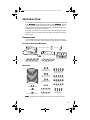
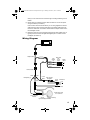
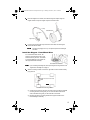
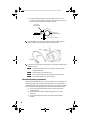
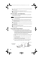
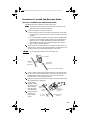
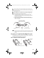
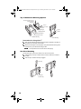
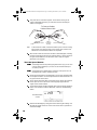
General-Duty &
Heavy-Duty
Installation
Manual
Product # 8156GD, 8156HD
&217(176
Introduction . . . . . . . . . . . . . . . . . . . . . . . . . . . . . . . . . . . . . . . . . . . . . . . . . . . . . . . . 1
Components . . . . . . . . . . . . . . . . . . . . . . . . . . . . . . . . . . . . . . . . . . . . . . . . . . . . . 1
Additional Documentation . . . . . . . . . . . . . . . . . . . . . . . . . . . . . . . . . . . . . . . . . . 3
Tools and Materials Needed . . . . . . . . . . . . . . . . . . . . . . . . . . . . . . . . . . . . . . . . 3
Planning Your Installation . . . . . . . . . . . . . . . . . . . . . . . . . . . . . . . . . . . . . . . . . . . . . 4
How DriveRight Works . . . . . . . . . . . . . . . . . . . . . . . . . . . . . . . . . . . . . . . . . . . . 4
Installation Overview . . . . . . . . . . . . . . . . . . . . . . . . . . . . . . . . . . . . . . . . . . . . . . 4
Do-It-Yourself? . . . . . . . . . . . . . . . . . . . . . . . . . . . . . . . . . . . . . . . . . . . . . . . . . . . 4
Planning Considerations . . . . . . . . . . . . . . . . . . . . . . . . . . . . . . . . . . . . . . . . . . . 4
Wiring Diagram . . . . . . . . . . . . . . . . . . . . . . . . . . . . . . . . . . . . . . . . . . . . . . . . . . 5
Installing DriveRight . . . . . . . . . . . . . . . . . . . . . . . . . . . . . . . . . . . . . . . . . . . . . . . . . 6
Procedure 1. Install the Speed Sensor . . . . . . . . . . . . . . . . . . . . . . . . . . . . . . . . 6
Procedure 2. Install the Harness Cable . . . . . . . . . . . . . . . . . . . . . . . . . . . . . . . 11
Procedure 3. Install the Adapter Cable . . . . . . . . . . . . . . . . . . . . . . . . . . . . . . . 12
Procedure 4: Install the DriveRight Console . . . . . . . . . . . . . . . . . . . . . . . . . . . 13
Procedure 5. Finish the Installation . . . . . . . . . . . . . . . . . . . . . . . . . . . . . . . . . . 15
Troubleshooting . . . . . . . . . . . . . . . . . . . . . . . . . . . . . . . . . . . . . . . . . . . . . . . . . . . . 17
Installation Checklist . . . . . . . . . . . . . . . . . . . . . . . . . . . . . . . . . . . . . . . . . . . . . 17
Answers to Common Questions . . . . . . . . . . . . . . . . . . . . . . . . . . . . . . . . . . . . . 18
Sensor Wire Continuity Test . . . . . . . . . . . . . . . . . . . . . . . . . . . . . . . . . . . . . . . 19
Supplement for DriveRight HD . . . . . . . . . . . . . . . . . . . . . . . . . . . . . . . . . . . . . . . . 20
Install the Speed Sensor Magnet . . . . . . . . . . . . . . . . . . . . . . . . . . . . . . . . . . . . 20
Technical Support . . . . . . . . . . . . . . . . . . . . . . . . . . . . . . . . . . . . . . . . . . . . . . . . . . 22
FCC Part 15 Class B Registration Warning
This equipment has been tested and found to comply with the limits for a Class B digital device, pursuant to Part
15 of the FCC Rules. These limits are designed to provide reasonable protection against harmful interference in a
residential installation. This equipment generates, uses, and can radiate radio frequency energy and, if not
installed and used in accordance with the instructions, may cause harmful interference to radio communications.
However, there is no guarantee that interference will not occur in a particular installation. If this equipment does
cause harmful interference to radio or television reception, which can be determined by turning the equipment on
and off, the user is encouraged to try to correct the interference by one or more of the following measures:
•
Reorient or relocate the receiving antenna.
•
Increase the separation between the equipment and receiver.
•
Connect the equipment into an outlet on a circuit different from that to which the receiver is connected.
•
Consult the dealer or an experienced radio/TV technician for help.
Changes or modification not expressly approved in writing by Davis Instruments may void the warranty and void
the user's authority to operate this equipment.
© Davis Instruments Corp. 1997-2003. All rights reserved.
DriveRight General-Duty & Heavy-Duty Installation Manual
Rev. D, November 7, 2003
Product # 8156GD & 8156HD
Document Part Number: 07395.043
Information in this document subject to change without notice.
This product complies with the essential protection requirements of the EC EMC Directive 89/
336/EC.
DriveRight is a registered trademark of Davis Instruments Corp. Windows is a trademark of
Microsoft Corporation. VELCRO is a trademark of Velcro Industries, Manchester, NH.
07395.043 DR GD Inst Rev D Body D146.fm Page 1 Monday, December 1, 2003 12:02 PM
, 1752'8&7,21
This manual provides installation instructions for the DriveRight 600 GD (General
Duty), *' , and DriveRight 600 HD (Heavy Duty), +'. Since the
specific installation details vary quite a bit from one vehicle to another, these
instructions are intended to be a general guide for professional installers or for
knowledgeable and experienced mechanics.
We strongly recommend that you read the entire manual before beginning the
installation. Be sure you understand each procedure thoroughly before starting
that procedure.
&RPSRQHQWV
Your DriveRight should come with all of the components shown below. Make
sure you have all necessary components before proceeding with the installation.
&RQVROH0RXQWLQJ%UDFNHWV
Battery (CR123 3V Lithium)
DriveRight Console
Visor Clip
Mounting Bracket
Right Angle Adapter Bracket
Double-Sided Foam Tape (4 strips)
Velcro® Tape (4 pair)
+DUGZDUH
#6 x 1/2" Pan Head
Self-Tapping Screws (3)
1/4-20 x 3/4" Hex Head
Machine Screws (5)
6-32 x 1/2" Flat Head
Machine Screws (3)
#6 x 1/2" Flat Head
Self-Tapping Screws (3)
1/4" Split Lock Washers (5)
1/4" Flat Washers (5)
Tie Wraps (12)
1/2" Brass Hex Nuts (2)
3/8" Flat Washer
3/8" Internal Tooth Lock Washer
1RWH
6-32 Nuts (3)
1/4"-20 Nuts (5)
#6 Split Lock Washers (6)
#6 Flat Washers (6)
#14 x 3/4"
Self-Tapping Screws
(4)
DriveRight hardware components include extra pieces not required for installation.
07395.043 DR GD Inst Rev D Body D146.fm Page 2 Monday, December 1, 2003 12:02 PM
+DUQHVVDQG$GDSWHU&DEOHV
Digital Input
Adapter Cable
Harness Cable
:LULQJ
Red +12V Wire
with Fuseholder (22 AWG)
Spade Terminal Sets
#8-10 Studs
1/4" Studs
(3.5 - 5 mm)
(6 mm)
Butt Splices (8)
(26-22AWG or 24-20AWG)
Black Ground Wire
(22AWG)
Blue Wire (2) with Fuseholder (22 AWG)
Fuses (4)
(3AG 1-1/4 x 1/4",
.25A, Slo-Blo)
Insulated Male Disconnects
(18-22AWG)
T-Tap Disconnects
Blue
Red (3)
(14-16AWG)
(18-22AWG)
In-Line Splice (5)
6SHHG6HQVRU
Sensor Mounting Bracket
(1) with DriveRight GD; (2) with DriveRight HD
Speed Sensor
Reed Switch
with Leads
Sensor Support Bracket
'ULYH5LJKW*'0DJQHW
Magnet
Large Tie Wraps (2)
Magnet Mount
&$87,21 The speed sensor magnet is extremely strong and will de-magnetize ATM cards and
credit cards, and may also affect sensitive electronic equipment.
07395.043 DR GD Inst Rev D Body D146.fm Page 3 Monday, December 1, 2003 12:02 PM
'ULYH5LJKW+'0DJQHW
The DriveRight HD speed sensor magnet includes the following components.
See “Supplement for DriveRight HD” on page 20.
❏
❏
❏
❏
Stainless Steel Cable Tie
Stainless Steel Magnet Mount
Magnet
Neoprene Rubber Strip
$GGLWLRQDO'RFXPHQWDWLRQ
Refer to the following documents for additional information on configuring and
using your DriveRight:
❏ The User’s Guide included with your DriveRight.
❏ The DriveRight Fleet Management Software (FMS) or Vehicle
Management Software (VMS) on-line help.
❏ The DriveRight FMS or VMS User’s Manual, provided in an Adobe
Acrobat PDF file in the DriveRight software program directory.
7RROVDQG0DWHULDOV1HHGHG
DriveRight installation may require some or all of the following tools and
materials. Please review the installation instructions and make sure you have all
necessary tools before proceeding with the installation.
1RWH
Additional tools may be required depending on your specific installation.
❏ Drill and drill bits:
•
•
•
❏
❏
❏
❏
❏
❏
❏
❏
❏
❏
❏
7/64” or 2.5mm (pilot hole for #6 self-tapping screws)
3/16” or 5mm (pilot hole for 1/4” self-tapping screws)
5/16” or 8mm (clearance hole 1/4” bolts)
Multimeter and/or test light
Hacksaw
Adjustable wrenches
Vise
Metal forming tools
Metal forming tools
Crimp tools
Wire cutter
Wire stripper
Various screwdrivers
Pliers
DriveRight Heavy Duty installation also requires one of the following tension tools
available from Davis Instruments or an equivalent tension tool. See “Supplement
for DriveRight HD” on page 20.
❏ Tension Tool for stainless steel cable tie, ❏ Deluxe Tension Tool for stainless steel cable tie, 07395.043 DR GD Inst Rev D Body D146.fm Page 4 Monday, December 1, 2003 12:02 PM
3 /$11,1* <285 , 167$//$7,21
+RZ'ULYH5LJKW:RUNV
DriveRight GD and HD use a a reed switch and rotating magnet to sense vehicle
speed. The speed sensor mounts on the driveshaft for rear wheel drive vehicles
or on one of the in-board CV-joint hubs for front wheel drive vehicles. Each time
the magnet passes the reed switch, the speed sensor sends a signal to console.
The console uses this signal to calculate vehicle speed, distance traveled, and
the rates of acceleration and deceleration.
,QVWDOODWLRQ2YHUYLHZ
The list below and the wiring diagram on the next page provide an overview of
DriveRight GD and HD installation.
Mount the speed sensor underneath the vehicle.
Run the sensor leads under the vehicle and into the vehicle cabin.
Connect the harness cable power, ground and speed sensor leads.
Connect the harness cable to the adapter cable.
Connect the adapter cable power, ground, and digital input leads.
Mount the DriveRight display on or near the dashboard and connect it to the
adapter cable.
Test the installation.
Calibrate the DriveRight speed readings. Refer to the DriveRight User’s
Guide for instructions.
'R,W<RXUVHOI "
Davis Instruments strongly recommends that DriveRight be installed by ASE
(Automotive Service Excellence) certified technicians or professional automotive
mechanics. Improper installation may damage your vehicle and possibly cause
accidents or injuries. If your DriveRight is installed by a professional, use the
“Installation Checklist” on page 17 to check the installation.
&$87,21 Installing DriveRight can be hazardous to both the installer and to the vehicle electrical
system. This manual assumes you are aware of the inherent dangers of working in and
around a vehicle and have a working understanding of electricity. If you are uneasy
about installing DriveRight, please have a qualified professional do the installation.
Davis specifically disclaims any liability for injury or loss resulting from the installation or
use of DriveRight.
3ODQQLQJ&RQVLGHUDWLRQV
Before you begin, please review the planning considerations listed below and
think through your installation. A little planning beforehand will save you time,
frustration, and parts.
❏ Determine the DriveRight console mounting location. (Procedure 4)
Knowing the console mounting location will help you decide where to connect and route the harness cable, the digital inputs, and the sensor leads.
❏ Determine the mounting locations for the speed sensor magnet and reed
switch and how to route the sensor wires into the vehicle. (Procedure 1)
07395.043 DR GD Inst Rev D Body D146.fm Page 5 Monday, December 1, 2003 12:02 PM
Often you can route the sensor wires through an existing feedthrough in the
firewall.
❏ Decide where to install the harness cable and where to connect the power
and ground leads. (Procedure 2)
Find a location inside the vehicle where you can bring together the harness
cable leads, the power and ground tap wires, the adapter cable leads, and
the sensor cable leads. The location should allow the adapter cable to reach
the DriveRight console.
❏ Determine where to connect the digital input leads (if used). Digital input 1 is
typically used to monitor brake lights and digital input 2 is used to monitor
headlights. (Procedure 3)
:LULQJ'LDJUDP
Display
Adapter Cable
Red
Butt
Splices
Green (2)
Blue Wires
with
In-Line
Fuses
Digital
Inputs
1
Yellow
2
Ground
Black
Harness Cable
White
Red
In-Line
Splice
Butt Splices (3)
Black
Red Wire with
Fuseholder
Red
In-Line
Splice
Unswitched
+12V
Ground
Spade Terminal
Vehicle Drive Shaft
or CV Joint Hub
Sensor Support
Bracket
Sensor
Magnet Assembly
Typical DriveRight Installation
07395.043 DR GD Inst Rev D Body D146.fm Page 6 Monday, December 1, 2003 12:02 PM
, 167$//,1* ' 5,9( 5 ,*+7
&$87,21 Always use safety stands when working under a raised vehicle. Never work under a
vehicle supported only by a jack.
3URFHGXUH,QVWDOOWKH6SHHG6HQVRU
The speed sensor used by the DriveRight GD and HD consists of a magnet
mounted on the driveshaft or CV-joint hub and a reed switch.
1. Mount the magnet on the vehicle’s driveshaft or CV-joint hub.
2. Assemble the reed switch bracket.
3. Install the reed switch.
4. Route the sensor leads into the vehicle.
,QVWDOOWKH0DJQHW5HDU:KHHO'ULYH
For a rear wheel drive vehicle,
the magnet mounts on the
driveshaft close to the
transmission. The sensor
mounts adjacent to the magnet
on the vehicle’s chassis or floor
pan.
1RWH
Rear Wheel Drive
Installation
If you are installing a DriveRight HD, see the special magnet mounting instructions in the
“Supplement for DriveRight HD” on page 20.
Select a mounting location on
the drive shaft within 12 inches
(30cm) of the universal joint to
account for vehicle suspension
movement while driving.
Drive Shaft
12" (30 cm)
Rear Wheel Drive Mounting Positions
❏ The mounting location should provide a clearance zone around the
driveshaft of at least 3/4” (19mm) and a 3/8”-1/2” (10 - 13 mm) gap
between the magnet and reed switch.
3/4" (19 mm)
Minimum Extension
3/4" (19 mm)
Minimum Clearance
3/8" - 1/2" (10 - 13 mm) Gap
07395.043 DR GD Inst Rev D Body D146.fm Page 7 Monday, December 1, 2003 12:02 PM
Place the magnet in its mount, then slide the large tie wrap through the
magnet mount to keep the magnet in place as shown below.
Tie Wrap
Vehicle Driveshaft
Magnet
Magnet Mount
Loosely cinch the large tie wrap around the drive shaft, with the magnet
mount oriented as shown.
1RWH
Keep the tie wrap slightly loose so you can adjust the position after installing the
reed switch.
,QVWDOOWKH0DJQHW)URQW:KHHO'ULYH
For a front wheel drive vehicle, the
magnet is mounted on the left or right
side in-board CV joint hub. The sensor
is mounted adjacent to the magnet on
the engine/transaxle assembly.
Front Wheel Drive Installation
1RWH
If you are installing a DriveRight HD, see the special magnet mounting instructions in the
“Supplement for DriveRight HD” on page 20.
Select a mounting location on the left or right side in-board constant velocity
(CV) joint hub.
In-board CV-Joint Hubs
Front Wheel Drive Mounting Positions
❏ Choose the in-board CV joint hub you want to use by looking at potential
mounting locations, seeing how you can route the wires into vehicle
cabin, and determining how you will make the connections.
❏ Mounting the sensor mounting bracket and support bracket on the
transaxle/engine assembly.
07395.043 DR GD Inst Rev D Body D146.fm Page 8 Monday, December 1, 2003 12:02 PM
❏ The gap between the magnet mount and sensor must be 3/8”-1/2”
(10-13mm). There should be a clearance zone of at least 3/4” (19mm)
above the drive shaft where the magnet is mounted.
3/4" (19 mm)
Minimum Extension
3/4" (19 mm)
Minimum Clearance
3/8" - 1/2" (10 - 13 mm) Gap
Place the magnet in its mount, then slide the large tie wrap through the
magnet mount to keep the magnet in place as shown below.
Tie Wrap
In-Board
CV Joint Hub
Magnet
Magnet Mount
Loosely cinch the large tie wrap around the CV joint with the magnet mount
oriented as shown.
1RWH
1RWH
1RWH
1RWH
Keep the tie wrap slightly loose so you can adjust the magnet position after
installing the reed switch.
Do not overlap the CV-joint boot with tie wrap.
Do not mount the bracket on the vehicle chassis because of engine torque.
Do not use fluid retaining bolts to retain the brackets.
%UDFNHW$VVHPEO\*XLGHOLQHV
Refer to these guidelines when you mount the speed sensor. The illustration on
the following page shows a typical bracket assembly. Due to the variations in
individual vehicles, adapt the bracket as necessary to fit your particular vehicle
and to maintain the required gap between the speed sensor and the magnet.
❏ The end of the reed switch must extend 3/4” (19mm) beyond the
mounting bracket.
❏ The bracket must not protrude below other parts on the vehicle
underbody.
❏ The support bracket is reinforcing the mounting bracket against
vibration.
07395.043 DR GD Inst Rev D Body D146.fm Page 9 Monday, December 1, 2003 12:02 PM
The bracket shown below provides a rigid mount for the speed sensor.
Mounting Bracket
Support Bracket
Speed Sensor
Reed Switch
At low speeds excessive vehicle vibrations can cause erroneous readings if the
sensor mounting bracket doesn’t provide adequate support. A correctly assembled bracket is shown below along with an example of a bracket assembled the
wrong way.
The Correct Way to Assemble the
Sensor Mounting Bracket:
The Wrong Way:
Sensor Mounting Bra
Support Bracket
Speed Sensor
Reed Switch
Support Bracket
Mounting Bracket
0RXQWWKH6HQVRU5HDU:KHHO'ULYH
On rear wheel drive vehicles the sensor is mounted on the chassis or floor pan
adjacent to the magnet.
&$87,21 Determine what’s behind the sensor bracket mounting surface before you install the
bracket so you won’t accidentally penetrate fuel lines, brake lines, vacuum lines, control
cables or electrical wiring.
Choose the mounting location for the sensor mounting bracket and support
bracket. Make sure the support bracket is reinforcing the sensor mounting
bracket against vibration.
Adjust the bracket assembly for the proper gap between the reed switch tip
and the magnet.
07395.043 DR GD Inst Rev D Body D146.fm Page 10 Monday, December 1, 2003 12:02 PM
Adjust the magnet mounting position so that the magnet passes opposite the
tip of the sensor.
Cinch magnet mount tie wrap tight against drive shaft.
Check the alignment of the magnet mount with end of sensor by spinning
tires if possible.
0RXQWWKH6HQVRU)URQW:KHHO'ULYH
On front wheel drive vehicles the sensor is mounted on the engine/transaxle
assembly adjacent to the magnet.
&$87,21 Determine what’s behind the sensor bracket mounting surface before you install the
bracket so you won’t accidentally penetrate fuel lines, brake lines, vacuum lines, control
cables or electrical wiring.
Choose mounting locations for the sensor mounting bracket and support
bracket. Make sure the support bracket reinforces the sensor mounting
bracket against vibration.
Adjust the bracket assembly for the proper gap between the reed switch tip
and the magnet.
Adjust the magnet mounting position so that the magnet passes opposite the
tip of the sensor.
Cinch tie wrap tight against CV joint hub.
Check the alignment of the magnet mount with end of sensor by spinning
tires if possible.
6HQVRU:LUH5RXWLQJ*XLGHOLQHV
Route the sensor wires into your vehicle using the following guidelines.
❏ Use the split flexible tubing to protect the sensor wires from the sensor
mounting bracket up to where they enter the vehicle cabin. The tubing
can be cut into pieces and used to protect the wires from sharp points
and edges or where the leads are tie wrapped to the underbody. Also
use the tubing where the wires are particularly exposed.
❏ Use the small tie wraps to hold the leads against the underbody of your
vehicle.
❏ If a vehicle wire bundle is readily accessible, route the sensor leads
along this wire bundle.
❏ The sensor leads should be routed at least 12” (30 cm) away from
sparkplug wires, the coil, and the alternator.
❏ Loops, coils, and folds should be avoided in order to avoid creating
unwanted interference that might result in erroneous readings.
Small Tie Wrap
Use flexible tubing to
protect wiring
Split Flexible Tubing
07395.043 DR GD Inst Rev D Body D146.fm Page 11 Monday, December 1, 2003 12:02 PM
3URFHGXUH,QVWDOOWKH+DUQHVV&DEOH
&RQQHFW9'&3RZHUDQG*URXQG/HDGV
DriveRight requires an unswitched +12 VDC power source.
1RWH
The wire used for power and ground connections should be 22-18AWG or have the
same diameter as the red +12V wire with fuseholder.
Locate an unswitched +12 VDC power source:
❏ Make a direct connection in the fusebox (recommended) - either using
an extra accessory slot in the fuse box or using a fuse tap connector (not
supplied).
❏ Or, use the supplied in-line splice connectors to tap into a known circuit
that does not involve safety related equipment such as headlights, tail
lights, air bag, etc. Possible candidate wires include those from the
cigarette lighter, dome light, glove compartment light, clock, tail gate
light, or other convenience functions.
Tap a red wire from the fuse holder to the unswitched +12 VDC source you
located in Step 1. Use the in-line splice provided with your DriveRight or use
a fuse tap connector (not included) appropriate for your vehicle.
&$87,21 Do not install the fuse into the fuse holder until instructed to do so.
In-Line Splice
Unswitched
+12V
from Vehicle
Trim off flush
stripped wire
Red +12V Wire with Fuseholder
Locate or make a vehicle chassis ground connection for the harness cable.
You can make one by inserting a spade terminal under the head of a screw
threaded into the vehicle chassis. Be sure to test the connection with a
multimeter before connecting the ground wire.
Butt splice the black ground wire from the harness cable to the black ground
wire included with your DriveRight.
Crimp a spade
terminal, included
with the unit, to the
other end of the
black wire. Refer
to the illustration.
Connect the spade
terminal to the
vehicle chassis
ground.
Vehicle
Ground
Spade
Terminal
3/16 - 1/4"
(5 - 6 mm)
Crimp Tool,
22-18 AWG Position
(red dot)
Black Ground Wire
(22 AWG)
07395.043 DR GD Inst Rev D Body D146.fm Page 12 Monday, December 1, 2003 12:02 PM
&RQQHFW3RZHU*URXQGDQG6HQVRU/HDGV
1RWH
Make sure the wiring harness extends to the DriveRight console mounting location when
making the following connections.
Strip the white sensor wire and the white harness cable wire 3/16”- 1/4”
(5-6 mm) then connect the wires using a butt splice.
Strip the red +12 VDC tap wire and the red harness cable wire 3/16”- 1/4”
(5-6 mm) then connect the wires using a butt splice.
Strip the black chassis ground tap wire and the black harness cable wire 3/
16”- 1/4” (5-6 mm) then connect the wires using a butt splice.
Install the fuse into the fuse holder in the red +12 VDC wire.
Use a small tie wrap to secure and protect the connections under the dash.
&$87,21 If the connections are on the driver’s side, make sure the wires can not become
entangled in the vehicle pedals or driver’s feet.
3URFHGXUH,QVWDOOWKH$GDSWHU&DEOH
Two digital inputs located on the adapter cable are available to monitor the on/off
state of lights, including brake lights, or of other 12 VDC electrical accessories.
Typically Digital Input 1 is connected to the brake lights and Digital Input 2 is
connected to the headlights. In the DriveRight software Digital Input 1 is recorded
in the GPS table and in the accident logs. Digital Input 2 is only recorded in the
GPS table.
❏ You can record the digital input status during a trip by enabling GPS in
DriveRight FMS, even if you aren’t using the optional GPS module.
❏ The adapter cable is required for DriveRight 600 even if you do not use
the digital inputs.
&$87,21 Connecting the digital inputs can be hazardous to both the installer and your vehicle’s
electrical system if not done by an experienced installer. This manual assumes you are
aware of the inherent dangers of working in and around a vehicle and have a working
understanding of electricity.
If you are not using the digital inputs go to Step 7 of this procedure.
Use an in-line splice to connect the red +12 VDC wire from the adapter cable
to the red +12 VDC wire in the harness cable. Be sure the tap is protected by
the harness cable fuse. Refer to the “Wiring Diagram” on page 5.
In-Line Splice
Red +12VDC
Harness Cable Wire
Trim off flush
stripped wire
Red +12VDC
Adapter Cable Wire
07395.043 DR GD Inst Rev D Body D146.fm Page 13 Monday, December 1, 2003 12:02 PM
Connect the black ground wire from the adapter cable to chassis ground.
Use in-line butt splices to connect the blue wires with fuses to the green and
yellow digital input cables.
Connect digital input 1 to the desired circuit, typically the brake light circuit.
Connect digital input 2 to the desired circuit, typically the headlight circuit.
Connect the adapter cable to the harness cable.
❏ It is easiest to make the connection if you hold the harness cable
connector by the connector housing and hold the adapter cable by the
cable next to the connector.
❏ Push the two connectors together. The connector housing on the
adapter cable slides back when you make the connection, allowing the
cables to lock together.
To Connect Cables,
Hold as Shown Here
Harness Cable
1RWH
Sliding
Connector
Housing
Adapter Cable
To disconnect the cables, hold the both cables by the housing and pull apart. The sliding
housing on the adapter cable connector will release the lock and allow the cables to be
separated.
3URFHGXUH,QVWDOOWKH'ULYH5LJKW&RQVROH
The DriveRight console can be mounted in a number of places, including the top
of the dash, on the face of the dash, or on a sun visor.
)DFHRI'DVKERDUG0RXQWLQJ2SWLRQV
OR
Mounting
Bracket
Double-Sided
Foam Tape
Mounting
Bracket
Flat Head Self-Tapping Screw (2x)
07395.043 DR GD Inst Rev D Body D146.fm Page 14 Monday, December 1, 2003 12:02 PM
7RSRI'DVKERDUG0RXQWLQJ2SWLRQV
Pan Head Self-Tapping Screw
Split-Lock Washer
Flat Washer
Hex Nut
Split-Lock Washer
Flat Washer
Loops
Right Angle
Adapter Bracket
Hooks
Mounting Bracket
Flat Head Machine Screw
Bracket Mounting
Velcro Mounting
®
Instructions for Using Velcro :
Apply the two adhesive-backed Velcro loop tapes to the flats on the back of
the console or to the back of the bracket.
Attach the hook tapes to the loop tapes, then press adhesive backing of the
hook tape onto your selected mounting surface.
1RWH
Do not separate the Velcro for at least 24 hours after applying.
6XQ9LVRU0RXQWLQJ
Use the visor clip to mount your console on a visor or door pocket.
Install the clip on the top or bottom of the console to orient the console as
you wish.
Push the clip in until the 3rd bump engages.
Visor Clip
OR
3 Bumps
(to hold clip)
07395.043 DR GD Inst Rev D Body D146.fm Page 15 Monday, December 1, 2003 12:02 PM
3URFHGXUH)LQLVKWKH,QVWDOODWLRQ
Use the following steps to finish the installation.
&$87,21 It is not necessary to enter a code in order to perform this test. DO NOT ENTER A
CODE UNTIL YOU READ THE USER’S MANUAL.
,QVWDOOWKH%DWWHU\
Insert the battery into the DriveRight console as shown below.
The screen you should see is the current readings screen. The word “BAT”
should appear in the lower left corner, indicating that the unit is operating on
battery power.
Indicates Unit Running on Battery Power
Press and hold 02'( for 3-5 seconds until the last correct code screen
appears.
If you have already used the console, you may see the tamper time screen
instead. If so press 02'( once to display the last correct code screen.
Figure 1: Last Correct Code Screen
&RQQHFWWKH&RQVROH
With the ignition off, connect the adapter cable to the console cable.
It is easiest to make the connection by first holding the adapter cable by the
connector housing and holding the console cable by the cable itself next to
the sliding connector housing.
07395.043 DR GD Inst Rev D Body D146.fm Page 16 Monday, December 1, 2003 12:02 PM
Then push the two connectors together. The connector housing on the
console cable slides back when you make the connection, allowing the
cables to lock together.
To Connect Cables,
Hold as Shown Here
Adapter Cable
Note:
Sliding
Connector
Housing
Console Cable
To disconnect the cables, hold the both cables by the connector housing
and pull apart. The sliding housing on the console cable connector will
release the lock and allow the cables to be separated.
When the two cables are connected, the “BAT” should disappear, indicating
that the unit is drawing power from the vehicle’s battery. A dot may appear to
the right of where BAT was. This dot will be used to verify the magnet
placement in the next step.
7HVWWKH6SHHG6HQVRU
1RWH
1RWH
The DriveRight comes with sample data pre-programmed into the log so you can use all
of the unit’s features immediately. As you use the unit, this data will automatically be
over-written by new data.
The DriveRight must be calibrated before it will display the correct speed. Look in the
DriveRight 600 User’s Guide for calibration instructions.
Roll the car forward slowly so the driveshaft or CV joint hub complete at least
one complete revolution. You should perform this test while the vehicle is on
the ground and not on the stand.
As the vehicle suspension takes up the weight of the vehicle, the driveshaft
and CV joint hub move. The sensor must be properly aligned with the
magnet in this normal condition.
The dot should appear and then disappear each time the magnet passes the
sensor. If the dot does not flash as described, consult the Troubleshooting
section.
Dot Position at Bottom
of Screen
Road test the DriveRight by driving around and observing the readings. You
will need two people for this test: one to drive and the other to operate and
read the DriveRight.
07395.043 DR GD Inst Rev D Body D146.fm Page 17 Monday, December 1, 2003 12:02 PM
7528%/(6+227,1*
,QVWDOODWLRQ&KHFNOLVW
Use the following list to check a professional DriveRight installation or to help
spot potential problems in an installation.
White sensor wire is connected to the white wire of the harness cable.
Crimp connector must be properly crimped.
Black sensor wire is connected to the black wire of the harness cable.
Crimp connector must be properly crimped.
Sensor leads should be protected with split tubing and tie wrapped in place.
Wires should be routed at least 12” (30cm) away from sparkplug wires, the
coil, and the alternator. Loops, coils, and folds should be avoided in order to
avoid creating unwanted interference that might result in erroneous readings.
Unswitched +12V from your vehicle is connected to the red wire of the
harness cable.
❏ Fuse must be installed and unbroken.
❏ In-line splices and /or crimp connectors must be properly crimped.
❏ “BAT” does not appear on display when ignition is off and console is
operating and plugged into harness cable.
Ground connection from your vehicle is connected to the black wire from the
sensor.
❏ In-line splice and spade terminal must be properly crimped.
❏ Screw head fastening the spade terminal must make contact to the
vehicle’s metal chassis.
Sensor installation is completed as directed.
❏ Sensor and magnet location on driveshaft or inboard CV joint as
directed.
❏ Magnet mount with magnet in place cinched tight and free to rotate.
❏ Magnet mount aligned with sensor tip and passing within
3/8”- 1/2 (10-13 mm).
❏ Sensor tip protruding 3/4” (19 mm) beyond the sensor mounting bracket.
❏ Sensor bracket properly reinforced by support bracket against vibration.
❏ All fasteners properly installed and screwed down tight.
❏ No portion of sensor installation protruding below other nearby
components under the vehicle.
Console is installed and tested as directed.
❏ Battery is installed, “BAT” is indicated on screen prior to connecting to
harness cable.
❏ “BAT” disappears when console is plugged into harness cable with
ignition off.
❏ DOT (“.”) appears and disappears if wheels are rotated or vehicle moves
very slowly forward.
07395.043 DR GD Inst Rev D Body D146.fm Page 18 Monday, December 1, 2003 12:02 PM
$QVZHUVWR&RPPRQ4XHVWLRQV
“BAT” stays on when console is connected to harness cable.
The wire connections to the harness cable are probably not correct. Inspect
your wiring. See Steps 1 to 5 in the “Installation Checklist” on page 17.
“BAT” comes on when ignition is turned off and console is plugged into
harness cable.
The DriveRight console is connected to switched +12V instead of
unswitched +12V. Connect to unswitched +12V. See “Connect +12VDC
Power and Ground Leads” on page 11.
“BAT” appears when console is connected to harness cable but flashes off
when dot appears. See Step 4 on page 16 for a description of the dot.
The black and white wires from the sensor are connected backwards to the
black and white wires of the harness cable or the ground connection to the
vehicle’s chassis is spliced to the white sensor wire. Inspect your wiring. See
Steps 1 to 5 in the “Installation Checklist” on page 17.
Dot does not appear when console is plugged into the harness cable and
wheels are rotated (“BAT” is off).
The sensor installation may be incorrect. See Step 6 in the “Installation
Checklist” on page 17.
Speed is zero when driving.
It is possible that you simply have not calibrated the DriveRight (see the
User’s Guide for instructions.) If your speed remains zero, the sensor may
not be close enough to or properly aligned to the magnet mount. Inspect
sensor installation with vehicle resting on its wheels. Check positions of sensor tip and magnet mount. If not aligned, see Step 6 in the “Installation
Checklist” on page 17. If sensor appears aligned properly and speed
remains zero, perform the “Sensor Wire Continuity Test” on page 19.
Speed reading is intermittent while driving at constant speeds.
The sensor mounting bracket may be interfering with the magnetic field.
MAKE SURE THE SENSOR END PROTRUDES 3/4” (19 mm) FROM THE
SENSOR MOUNTING BRACKET.
Otherwise, there may be too much movement in the driveshaft or in-board
CV joint causing the magnet mount to be too far from the sensor tip on occasion, or the connections may be loose. To fix this problem, inspect sensor
installation with the vehicle resting on its wheels. Check positions of sensor
tip and magnet mount. If not aligned, see Step 6 in the “Installation Checklist”
on page 17.
❏ Move sensor and magnet mount closer to universal joint on rear wheel
drive vehicles.
❏ Check vertical alignment of sensor bracket if bracket is mounted on the
vehicle chassis, consider mounting bracket to engine.
❏ If the brackets are properly installed, perform the “Sensor Wire
Continuity Test” on page 19.
Screen goes blank when attached to harness cable.
The console is going into “sleep” mode. This only happens when the unit is
running on battery power. Inspect your wiring. See Steps 1 to 5 in the “Installation Checklist” on page 17.
07395.043 DR GD Inst Rev D Body D146.fm Page 19 Monday, December 1, 2003 12:02 PM
Knocking sounds are coming from under the vehicle.
The magnet is hitting the vehicle or mounting bracket while rotating. Inspect
the sensor installation and reinstall as needed. See “Procedure 1. Install the
Speed Sensor” on page 6.
Current Readings are zero but everything appears properly installed.
You may have loose or poor connections and/or a broken wire inside of wire
insulation. Use the “Sensor Wire Continuity Test” on page 19 to locate problem wiring. Tighten crimps and/or replace wire.
6HQVRU:LUH&RQWLQXLW\7HVW
Unplug harness cable.
Use an multimeter or continuity tester to probe Pins 2 and 3 on the harness
connector.
•
•
•
•
Pin 1: Unswitched +12V
Pin 2: Sensor Signal
Pin 3: Ground
Pin 4: Unused
Position of Pins on Harness Connector
Roll vehicle forward.
Multimeter or continuity tester should indicate a short each time the magnet
passes the sensor tip. If so the sensor is operating properly
If no short is indicated, check the wiring carefully for breaks or loose
connections. Probe between the white wire of the harness cable as it enters
the butt connectors and Pin 2. Probe between the black wire of the harness
cable as it enters the butt connectors and Pin 3.
The multimeter or continuity tester should indicate a short. If so the harness
cable is unbroken.
Check the butt connectors carefully for loose connections by probing across
the butt splice for the white wires and then across the butt splice for the black
wires.
The multimeter or continuity tester should indicate a short. If so the butt connectors are properly crimped. If not, tighten crimps or replace crimps (two
extra butt connectors were provided with your DriveRight).
Check the sensor wires for nicks or other signs of damage, remove and
replace suspect sections, use 22 AWG UL1015 (105C) wire with 22-18 AWG
insulated (red) butt connectors available at your local hardware store.
07395.043 DR GD Inst Rev D Body D146.fm Page 20 Monday, December 1, 2003 12:02 PM
6 833/(0(17 )25 ' 5,9( 5 ,*+7 +'
,QVWDOOWKH6SHHG6HQVRU0DJQHW
Use these instructions to install the speed sensor magnet using a stainless steel
cable tie. The stainless steel cable tie provides a more secure magnet mount for
trucks or cars driven on unpaved roads or in other harsh environments.
6WDLQOHVV6WHHO&DEOH7LH,QVWUXFWLRQV
1RWH
Once the end of the cable tie is inserted into the
clasp, it cannot be removed. Do this only when you
are ready.
Measure the neoprene rubber strip. Wrap it
around the driveshaft at the location where the
magnet is to be mounted. Cut the rubber strip
squarely so that a 1.5” gap is left between the
ends. This gap is where the magnet will be
placed.
1.5" (38 mm)
± 0.25" (± 6 mm)
Driveshaft
or Axle
Neoprene
Rubber Strip
Install the magnet into the holder and slide the stainless steel cable tie into
the holder, securing the magnet inside. Note the orientation of the clasp to
the holder.
Magnet
Stainless Steel Cable tie
Magnet Holder
Place the neoprene rubber strip around the driveshaft and loosely wrap the
stainless steel cable tie over the rubber strip.
Driveshaft
or Axle
Magnet
Holder
Cable Tie Clasp
Stainless Steel
Cable Tie
Neoprene
Rubber Strip
Position the magnet holder in the 1.5” gap (the magnet holder should rest
directly on the shaft).
Insert the end of the stainless steel cable tie into the clasp and slowly tighten.
Position the clasp 180° from the magnet on the shaft. When everything is
properly in position, tighten the cable tie by hand.
Proceed to the tightening instructions for your tension tool.
07395.043 DR GD Inst Rev D Body D146.fm Page 21 Monday, December 1, 2003 12:02 PM
7LJKWHQ8VLQJWKH7HQVLRQ7RRO
, operates like a screw-driver and is best used for
The Tension Tool,
single installations.
Trim the stainless steel cable tie using cutters or tin snips so that 2” remains
protruding from the clasp.
Insert the end of the stainless steel cable tie into the slot at the end of the
tightening tool. Grip the tool by the handle and hold the magnet in place.
Slowly twist the tool to further tighten the cable tie. Rotate the tool so that the
tool tip goes down toward the clasp and under the remaining tie.
When the desired amount of tension has been reached and the magnet is
secure, slide the tool out of the center of the coil. Flatten the rolled coil
against the shaft.
Screwdriver-Type Tightening Tool
Cross Section of
Cable Tie After
Tensioning
7LJKWHQ8VLQJWKH'HOX[H7HQVLRQ7RRO
The Deluxe Tension Tool,
, incorporates a ratchet mechanism for extra
efficiency. This tool should be used if you are performing multiple installations.
Slide the Deluxe Tension Tool over
the stainless steel cable tie as
shown. Squeeze the handle to apply
tension.
If the handle is all the way closed
and more tension is needed, release
the handle and slide the tool towards
the clasp.
6WHS
Deluxe Tension Tool
Repeat
until the desired
tension has been reached.
To cut off the end of the cable tie,
hold tension in the tool and twist the
tool either clockwise or
counterclockwise.
07395.043 DR GD Inst Rev D Body D146.fm Page 22 Monday, December 1, 2003 12:02 PM
7(&+1,&$/ 6 83325 7
If you are experiencing problems with your DriveRight, first check the cable
connections and verify the calibration settings. If you are unable to solve the
problem, please call Davis Technical Support. We’ll be glad to help. Most
questions can be answered on the phone. You can also email us for support, or
visit our website. Sorry, we are unable to accept collect calls.
1RWH
Please do not return items for repair without prior authorization.
❏ (510) 732-7814 – Monday through Friday, 7:00 a.m. to 5:30 p.m. Pacific
Time.
❏
❏
❏
❏
(510) 670-0589 – Fax to Technical Support.
[email protected] – E-mail to Technical Support.
[email protected] – E-mail to Davis Instruments.
www.davisnet.com – Product documentation is available on the
DriveRight Support section of our website. Watch for FAQs and other
updates.
:DUUDQW\5HSDLU,QIRUPDWLRQ
2QH<HDU/LPLWHG:DUUDQW\
We warrant our products to be free of defects in material and workmanship for the period of one
year from the date of original purchase. While we make every effort to carefully manufacture our
products to the highest standards of quality, occasionally parts may be found to be missing,
defective, or damaged.
If you have a defective part, return the product to us, shipping charges pre-paid. Include proof of
purchase and a written explanation of the trouble. During the warranty period, we will, at our
option, either repair or replace the product free of charge.
This warranty does not cover damage due to improper installation or use, negligence, accident, or
unauthorized service, or to incidental or consequential damages beyond the Davis products
themselves. Implied warranties are limited in duration to the life of this limited warranty.
Some states do not allow limitations on how long an implied warranty lasts, or the exclusion or limitation of
incidental and consequential damages, so the above may not apply to you. This warranty gives you
specific legal rights. You may have other rights, which vary from state to state.
3465 Diablo Avenue, Hayward, CA 94545-2778 U.S.A.
510-732-9229 • Fax: 510-732-9188
E-mail: [email protected] • www.davisnet.com