1
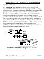
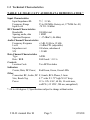
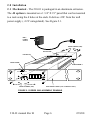
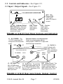
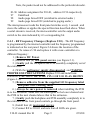
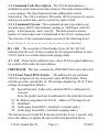
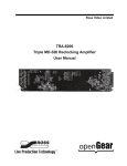
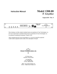
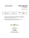
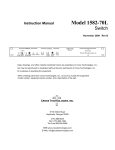
INSTRUCTION MANUAL
MODEL 210-01 CATV
RECEIVER
Data, drawings, and other material contained herein are
proprietary to Cross Technologies, Inc., and may not be
reproduced or duplicated in any form without the prior
permission of Cross Technologies, Inc.
When ordering parts from Cross Technologies, Inc., be
sure to include the equipment model number, equipment
serial number, and a description of the part.
First Edition, May 28, 1999
REV B 2/18/00
CROSS TECHNOLOGIES, INC.
6170 SHILOH ROAD
ALPHARETTA, GEORGIA 30005
Phone (770)-886-8005
Toll Free (888)-900-5588
FAX (770)-886-7964
WEB www.crosstechnologies.com
E-MAIL [email protected]
210-01 manual Rev B
Page 2
2/18/00
INSTRUCTION MANUAL
MODEL 210-01 CATV DEMODULATOR
TABLE OF CONTENTS
PAGE
Warranty ..............................................3
1.0 General.................................................4
1.1 Equipment Description..........................4
1.2 Technical Characteristics........................5
2.0 Installation ............................................6
2.1 M e c h a n i c a l . . . . . . . . . . . . . . . . . . . . . . . . . . . . . . . . . . . . . . . 6
2.2 Controls and Indicators..........................7
2.3 Input / Output Signals ..........................7
2.4 Installation / Operation..........................8
2.4.1 Installing and Operating the 210-01....8
2.4.2 Setting the Front Panel BCD Switch...8
2.4.3 RF Frequency Changes (Replace U10).9
3.0 Circuit Description..................................10
3.1 Block Diagram Description ...................10
3.2 Command Code Description ..................10
3.2.1 Command Stream .......................11
3.2.2 Front Panel BCD Switch...............11
3.2.3 Tuner Load.............................. 11
WARRANTY - The following warranty applies to all Cross Technologies, Inc.Products.
All Cross Technologies, Inc. products are warranted against defective materials and workmanship for a
period of one year after shipment to customer. Cross Technologies, Inc.’s obligation under this warranty is
limited to repairing or, at Cross Technologies, Inc.’ option, replacing parts, subassemblies, or entire
assemblies. Cross Technologies, Inc. shall not be liable for any special, indirect, or consequential damages.
This warranty does not cover parts or equipment which have been subject to misuse, negligence, or accident
by the customer during use. All shipping costs for warranty repairs will be prepaid by the customer. There
are not other warranties, express or implied, except as stated herein.
CROSS TECHNOLOGIES, INC.
6170 SHILOH ROAD
ALPHARETTA, GEORGIA 30005
Phone (770)-886-8005
Toll Free (888)-900-5588
FAX (770)-886-7964
WEB www.crosstechnologies.com
E-MAIL [email protected]
210-01 manual Rev B
Page 3
2/18/00
MODEL 210-01 CATV AUDIO/DATA DEMODULATOR
SECTION 1 GENERAL
1.1 Equipment Description - The Series 210-01 operates with
standard CATV cable systems to provide a paging system by receiving
the paging audio signal and a data control signal which determines if the
paging message is intended for the location it is programmed for.
Detected data is decoded to determine if the audio is intended for this
location as determined by the location code selected by two BCD
switches on the front panel. When the data matches the location code of
this unit, it switches audio from an external audio source to the paging
audio. A “Carrier Presence” LED , “Data Activity” LED, and “Power”
LED indicates the operating status of the Series 210-01 . Connectors are
RCA Phono plug for external audio in and switched audio out
(unbalanced), F connector for CATV in, and 2.1mm power connector.
Power is provided by a wall mount power supply.
CHANNEL
CONVERTER
55 - 300
MHZ CATV
INPUT
EXT AUDIO IN
AUDIO
DEMOD
AUDIO
SWITCH
AUDIO
OUT
SELECT
SWITCHES
DATA
DEMOD
DECODER
MODEL 210
AUDIO / DATA DEMOD
CROSS TECHNOLOGIES, INC.
DATA CARRIER
POWER
LOCATION CODE
FIGURE 1.1 210-01 Block Diagram and Chassis
210-01 manual Rev B
Page 4
2/18/00
1.2 Technical Characteristics
TABLE 1.0 210-01 CATV AUDIO/DATA DEMODULATOR *
Input Characteristics
Input Impedance/RL
Frequency Range
Input Level
RF Channel Characteristics
Bandwidth
Spacing, audio, data
Spurious Response
Audio Channel Characteristics
Frequency Response
Level
Impedance out
S/N
Data Channel Characteristics
Type
Rate / BER
Controls
Location Code
Indicators
Carrier; Data; DC Power;
Other
Connectors RF, Audio, DC
Size, Bench Top
Power
75 Ω /12 db
55 to 200 MHz (factory set, 177MHz for -01)
-70 TO -30 dBm
300 kHz total
1 MHZ
< -37 dBmV (-86 dBm)
±2 dB, 50 Hz to 12 kHz
+8 dBm PPL (adjustable)
100 ohms, unbalanced
> 50 dB
AFSK
9600 baud / >10^-6
Two BCD switches
Red/Green, Green, Green LEDs
F, female, RCA Phono, 2.1mm
4.7” wide X 1.75” high X 8.0” deep
115 ± 10% VAC, 60 Hz, 10 watts max,
wall PS (+12 VDC, 500 ma, unregulated)
*+10 to +40 degrees C; Specifications subject to change without notice
210-01 manual Rev B
Page 5
2/18/00
2.0 Installation
2.1 Mechanical - The 210-01 is packaged in an aluminum extrusion.
The -R option is mounted on a 1 3/4” X 19” panel that can be mounted
to a rack using the 4 holes at the ends. It derives +DC from the wall
power supply (+12V unregulated). See Figure 2.1.
WALL
POWER
SUPPLY
REAR SCREWS (4EA)
BACKPLANE
EXTRUSION
FRONT PANEL
PCB ASSEMBLY
CROSS TECHNOLOGIES, INC.
2004 TEST UPCONVERTER
-25 -45 -65
UP DOWN
1. 3 8 3
IF LVL REM GAIN
ALARM
FREQUENCY (GHZ)
FRONT SCREWS (4EA)
TUNE
RACK MOUNT PANEL (FOR -R MODELS ONLY)
FIGURE 2.1 SERIES 2000 ASSEMBLY DRAWING
210-01 manual Rev B
Page 6
2/18/00
2.2 Controls and Indicators - See Figure 2.2 .
2.3 Input / Output Signals - See Figure 2.3.
C ROSS T ECHNOLOGIES, INC.
210 AUDIO/DATA RECEIVER
DS3 - DC
Power LED Lights green
when DC power is
present
ADDRESS
DATA
S1, S2 - Address Select
BCD Switches - Select the
address for the zone for this
demodulator. Address 00
receives all zones.
CARRIER
DC
DS2 - Data Lights green
when data is
received
DS1 - Carrier Lights green
when carrier is
present, red
when absent
FIGURE 2.2 210-01 Front Panel Controls and Indicators
J1 - DC POWER - The
+12 VDC unregulated DC
voltage from the wall power
supply
GND
+12
External Audio Level Adjustment Single turn potentiometer adjusts
external audio. CAREFULLY adjust with
small flat blade screwdriver.
C ROSS T ECHNOLOGIES, INC.
DC POWER
J1
J3 - RF Input - The
50 to 300 MHz input .
This is a 75Ω, F, female
connector at -20 to -70
dBm input level.
RF IN
AUDIO
OUT
J3
J2
J2 - Audio Out - The switched
audio output adjustable from +8
to -10 dBm measured into 600Ω.
This is a 100Ω impedance, RCA
Phono jack output.
AUDIO
LEVEL
J4 - Audio In External audio
input. This is a
10 kΩ impedance,
RCA Phono jack
input.
R47 - Audio Level - Ten
turn potentiometer which
adjusts switched paging
audio output from +8 to -10
dBm measured into 600Ω.
FIGURE 2.3 210-01 Rear panel Inputs, Output, Control
210-01 manual Rev B
Page 7
2/18/00
2.4 Installation / Operation 2.4.1 Installing and Operating the 210-01(Figures 2.1 to 2.3) 1.) Place the 210-01 where desired. (Attach four rubber feet if desired.)
2.) For the -R rack mount option mount the 1 3/4” panel to a rack using
the four end screws on the rack panel.
3.) Connect the wall power supply to 115 VAC, 60 Hz and the power
supply 2.1 mm DC connector to the 210-01 (Figure 2.1)
4.) Observe that green power LED (DS1) is illuminated.
5.) Connect RF In, J3 of the 210-01 to the cable TV connector using a
75Ω cable.
6.) Observe that the green Carrier and Data LEDs are illuminated.
7.) Connect the external External Audio In to J4
8.) Connect the Audio Out, J3 to the external audio amplifier
9.) Set the Address BCD switches to the desired number
10.) Set rear panel Audio Level pot, R47 to the desired paging volume.
11.) Using a small flat blade screwdriver, CAREFULLY adjust the
external audio level through the hole on the top back of the chassis.
12.) Note the proper pages reach this location and check address setting
if there are any problems.
13.) ADDRESS TEST POSITION SETTINGS. The following Address
BCD Switch settings may be helpful for troubleshooting.
00 -Audio will be switched ON if a valid packet is received.
Note, the packet need not be addressed to the particular decoder.
98- Audio page forced OFF ( switched to external audio )
99- Audio page forced ON ( switched to paging audio )
2.4.2 Setting the Front Panel BCD Switch - The address for any
particular 210-01 is assigned via two front panel rotary BCD switches.
These switches provide a possibility of 100 settings, displaying 00-99.
These settings are assigned as follows:
00 Special function Audio will be switched ON if a valid packet is
received.
210-01 manual Rev B
Page 8
2/18/00
Note, the packet need not be addressed to the particular decoder.
01-96 Address assignment for 210-01, address 01 96 respectively
97
Undefined
98
Audio page forced OFF (switched to external audio )
99
Audio page forced ON (switched to paging audio )
The microprocessor reads the front panel switches every 1 second , and
stores the address or applies the special function described above. When
a serial stream is received, the microcontroller sets the output audio
switch to the state indicated by it’s corresponding bit.
2.4.3 - RF Frequency Changes (Replace U10) - The RF frequency
is programmed by the internal controller and the frequency programmed
is indicated on the rear panel. Figure 2.4 shows the location of the
controller. To remove U10 and replace it with a new controller at a
different frequency:
1.) Remove DC Power.
2.) Remove four (4) rear panel screws (see Figure 2.1).
3.) Gently pull the backplane and PCB assembly completely out of
the extrusion.
4.) With the wall power supply disconnected, and TAKING
PROPER ESD PRECAUTIONS Replace U10 and install new
controller. CAUTION! BE SURE PIN I OF U10 IS AS SHOWN
(Figure 2.4).
5.) Remove adhesive from the supplied LO frequency label
and place over existing label
6.) Always be sure power is removed when installing the PCB
in to the extrusion. Make sure the shield goes in the lower channel and
the PCB in the next channel above that in the extrusion.
7.) Gently push the backplane and PCB assembly completely in to
the extrusion so the front panel controls go through the front panel.
8.) Install four (4) rear panel screws.
9.) Connect RF to 210-01 and note that all LEDs are green.
210-01 manual Rev B
Page 9
2/18/00
3.0 Circuit Description
CHANNEL
CONVERTER
55 - 300
MHZ CATV
INPUT
A1,
Q1 -4
EXT AUDIO IN
AUDIO
DEMOD
U1,3,5,9
DATA
DEMOD
U3,4,7
AUDIO
SWITCH
AUDIO
OUT
U6
DECODER
SELECT
SWITCHES
S1 S2
U10
FIGURE 3.1 210-01 Block Diagram
3.1 Block Diagram Description - 210-01 (Figure 3.1) - The 50 to
300 MHz input (J1) signal first goes to the CATV tuner A1 which
converts the desired input frequency to a 45 MHz IF. Commands to
select the tuner frequency are provided serially from microcontroller
U10. The 45 MHz signal then goes to the bandpass filter consisting of
Q1 - Q4 and associated circuitry. This signal next goes to FM
demodulator consisting of U1,U9 and associated circuitry. U3B and
U5A provide a 12 kHz lowpass filter for the audio signal and U5B is the
output audio amplifier.
The demodulated FM signal from U1, U9 also goes to 21 - 31 kHz
bandpass filter which selects the AFSK data carrier which is sent to the
AFSK demodulator U7. This 9600 b/s ASYNC data goes to
microcontroller U10 which decodes the incoming 9600 kB/s ASYNC
data stream, detects the desired state of the output audio switch U6 and
provides the switch command signal to audio switch U6 based on the
position of the BCD address switches S1, S2. Crystal Y1 determines the
3.6864 MHz clock frequency for the microcontroller U10. VR1 and
VR2 provide regulated +5 and +9.5 voltages and U8 provides
-9.5 VDC. Unregulated +12 VDC is connected to J1. LEDs DS1, DS2,
and DS3 provide indications of carrier presence, data activity, and DC
power, respectively.
210-01 manual Rev B
Page 10
2/18/00
3.2 Command Code Description - The 210-01 demodulates a
multiplexed audio channel and data channel. The audio channel delivers
a voice paging. The data channel provides addressable control
information. The 210-01 utilizes a Microchip 16C63 processor to receive
and process control data, and to control the audio switch.
3.2.1 Command Stream - The command stream is provided as an
Asynchronous RS232 data channel, running at 9600 baud, with NO
parity, 8 bits/character, and 1 stop bit. This data stream contains
packets of control data, and is transmitted to the 210-01 continuously.
The structure of the command stream consists of the following bytes:
H1 | H2 | H3 | H4 | A1 | A2 | A3 | A4 | A5 | A6 | A7 | A8 | A9 | A10 | A11 | A12 | CHECKSUM
H1 - H4 - The reception of fixed header bytes, H1 H2, H3, H4
indicates that the next 12 bytes contain the bit assigned address of each
210-01 which is to enable and provide paging audio.
A1 A12 -These twelve address bytes, select 96 bit assigned addresses,
for control of the audio for each address.
CHECKSUM - This byte contains the CHECKSUM for error detection.
3.2.2 Front Panel BCD Switch - The address for any particular
210-01 is assigned via two front panel rotary BCD switches. These
switches provide a possibility of 100 settings, displaying 00-99. These
settings are assigned as follows:
00 Special function Audio is be switched ON if a valid packet is
received.
Note, the packet need not be addressed to the particular decoder.
01 96 Address assignment for 210-01, address 01 96 respectively
97 Undefined
98 Audio page forced OFF ( switched to external audio )
99 Audio page forced ON ( switched to paging audio )
The microprocessor reads the front panel switches every 1 second , and
stores the address or applies the special function described above.
210-01 manual Rev B
Page 11
2/18/00
3.2.3 Tuner Load - The microprocessor programs the tuner, A1. The
microprocessor refreshes the tuner approximately every 30 seconds.
CROSS TECHNOLOGIES, INC.
6170 SHILOH ROAD
ALPHARETTA, GEORGIA 30005
Phone (770)-886-8005
Toll Free (888)-900-5588
FAX (770)-886-7964
WEB www.crosstechnologies.com
E-MAIL [email protected]
210-01 manual Rev B
Page 12
2/18/00