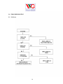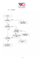
1
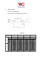
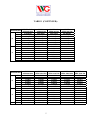
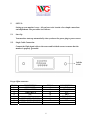
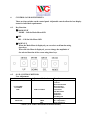
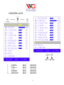
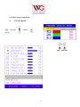
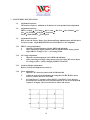
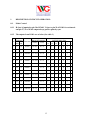
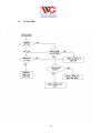
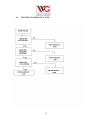
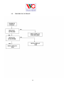
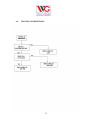
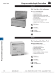
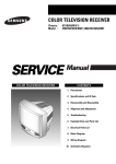
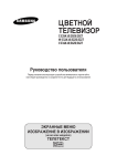
Service Manual for
D9100 Series
Digital-Control Color Monitor
Wells-Gardner Electronics
9500 W. 55th Street, Suite A
McCook, IL 60525-3605
(708) 290-2100
069X3015-100
Revision: A / E01023
Date: 7-27-00
Printed on 02/11/04
INDEX
1.
SAFETY PRECAUTION……………………………… 1
2.
SPECIFICATION……………………………………… 2
3.
TECHNCIAL FEATURES……………………………. 3
4.
TIMING CHART………………………………………. 4
5.
SET UP………………………………………………….. 6
6.
CONTROLS AND ADJUSTMENT…………………... 7
7.
ADJUSTMENT SPECIFICATION…………………… 10
8.
DESCRIPTION OF CIRCUIT OPERATION………...13
9.
TROUBLE SHOOTING……………………………….. 18
ii
1.
SAFETY PRECAUTION:
WARNING: Service should not be attempted by anyone unfamiliar with the
necessary precautions on this unit. The following precautions are
necessary during servicing.
1-1
Some parts, such as a picture tube in this unit, have special safety-related
characteristics for X-RAY RADIATION protection.
For continued safety, the parts replacement should be undertaken referring to below
article (1-2 and 1-5).
1-2
Many electrical mechanical parts in this unit have special safety-related characteristics
for protection against shock hazard and others. These characteristics are often passed
unnoticed by visual inspection and the protection afforded by them cannot necessarily
be obtained by using replacement components rated for higher voltage, wattage, etc.
Replacement parts which have these special characteristics are identified in the manual
and supplements by shading on the schematic diagram and the parts list. Before
replacing any of these components, read the parts list in this manual carefully.
1-3
When replacing the chassis in the cabinet, always be certain that all the protective
devices are installed properly, such as insulating covers, strain relief, etc.
1-4
Before replacing the back cover of the set, thoroughly inspect the inside of the cabinet
to see that no stray parts or tools have been left inside.
1-5
Before returning the set to the customer, always perform an AC leakage current check
on the exposed metallic parts of the cabinet, such as terminal, screwheads, metal
overlays, control shafts, etc. To insure the set is safe to operate without danger of
electrical shock, plug the AC line cord directly into a 120V AC outlet (do not use a line
isolation transformer during this check). Use an AC voltmeter having 5000 ohms per
volt or more sensitivity in the following manner. Connect a 1500 ohm, 10 watt resistor,
parallel with a (0.15uF) capacitor. Reverse the AC plug in the AC outlet and repeat the
AC voltage measurements for each exposed metallic part. Voltage measured must not
exceed 0.3V RMS. This corresponds to 0.2mA AC, any value exceeding this limit
constitutes a potential shock hazard and must be corrected immediately.
1
2.
SPECIFICATION:
2-1.1 Picture Tube.
• Size: 14”, 15”, 17”, 19”(18V)
• Dot Pitch: 14” : 0.26 – 0.28mm
15” : 0.26 – 0.28mm
17” : 0.26 – 0.28mm
19” (18V): 0.25mm
2-1.2 Signal Input.
• Video Input: Analog, Positive Signal (0.7V p-p)
• Horizontal Sync: TTL Level, Positive or Negative Pulse
• Scanning : 28 KHz-70KHz
• Vertical Input: TTL Level, Positive or Negative pulse
• Scanning : 40-160Hz
2-1.3 Power Supply.
• Power Input : 120-240 VAC, 50/60Hz
• Fuse Rating: 250V, 3.15A
• Power Consumption
14inch : less than 70W
15inch : less than 80W
17inch : less than 95W
19inch : less than 110W
2-1.4 OSD (On Screen Display) Control:
Refer to page 7
2-1.5 Operating Temperature: 0°C - 55°C
2-1.6 Operating Humidity: 10% - 90% (Noncondensing)
2-1.7 Net Weight
14inch : 22 lbs. (10kg)
15inch : 24 lbs. (11kg)
17inch : 33 lbs. (15kg)
19inch : 37 lbs. (17kg)
2
3.
TECHNICAL FEATURES:
3.-1
Microprocessor control with OSD (On screen display menu).
Microprocessor recognizes the input computer signal and signal output from
the customer control board connected to the main board by a flat cable.
3-2
Universal AC Input Voltage.
Power supply operates on 120-240 VAC at 60/50Hz for use all over the world.
3-3.
Protection Circuit for over-current.
When an over-current condition occurs in the circuit, the protection circuit operates in
order to prevent the components from electrical shock or other risks.
3-4
Override function.
A (NO SIGNAL MESSAGE) is displayed on the screen if no signal is present at the
signal input cable while the monitor is powered on.
3-5
Control panel.
If you require different display characteristics other than the factory mode presets of
size, position, color settings, use the control panel to program it to your requirements
in each resolution mode. These adjusted settings are kept in memory even if you
change resolution mode or turn off the monitor.
3-6
I²C BUS control.
The monitor is designed with I²C BUS control for simplifying the circuitry.
The number of total components is less than 610 pcs.
3
4.
TIMING CHART:
Factory Pre-Set Timing Modes.
Horizontal and Vertical Timing Diagram for Table 1.
TABLE 1 :
DESCRIPTION
H
V
FH
A
B
C
D
E
POL.
FV
A
B
C
D
E
POL.
VIDEO
MODE 1
VGA 720*400
31.469KHz
31.778µs
3.813µs
1.907µs
25.422µs
0.636µs
NEGATIVE
70.087Hz
14.268ms
0.064ms
1.112ms
12.711ms
0.381ms
POSITIVE
ANALOG
MODE 2
VGA 640*480
31.469KHz
31.778µs
3.813µs
1.589µs
25.422µs
0.318µs
NEGATIVE
59.940Hz
16.683ms
0.064ms
0.794ms
15.253ms
0.064ms
NEGATIVE
ANALOG
4
MODE 3
8514/A 1024*768
35.552KHz
28.251µs
3.920µs
1.247µs
22.806µs
0.170µs
POSITIVE
86.960Hz
11.500ms
0.113ms
0.563ms
10.810ms
0.014ms
POSITIVE
ANALOG
MODE 4
S-VGA 680*480
37.500KHz
26.667µs
2.032µs
3.810µs
20.317µs
0.508µs
NEGATIVE
75.000Hz
13.333ms
0.080ms
0.427ms
12.800ms
0.027ms
NEGATIVE
ANALOG
TABLE 1 (CONTINUED) :
DESCRIPTION
H
V
FH
A
B
C
D
E
POL.
FV
A
B
C
D
E
POL.
VIDEO
DESCRIPTION
H
V
FH
A
B
C
D
E
POL.
FV
A
B
C
D
E
POL.
VIDEO
MODE 5, S-VGA
VESA 800*600
37.879KHz
26.400µs
3.200µs
2.200µs
20.000µs
1.000µs
POSITIVE
60.317Hz
16.579ms
0.106ms
0.607ms
15.840ms
0.026ms
POSITIVE
ANALOG
MODE 6
VGA 800*600
46.875KHz
21.333µs
1.616µs
3.232µs
16.162µs
0.323µs
POSITIVE
75.000Hz
13.333ms
0.064ms
0.448ms
12.800ms
0.021ms
POSITIVE
ANALOG
MODE 7 VGA
VESA 800*600
48.077KHz
20.800µs
2.400µs
1.280µs
16.000µs
1.119µs
POSITIVE
72.188Hz
13.853ms
0.125ms
0.478ms
12.480ms
0.722ms
POSITIVE
ANALOG
MODE 8
VESA 1024*768
48.363KHz
20.677µs
2.231µs
1.615µs
15.754µs
0.998µs
NEGATIVE
60.004Hz
16.666ms
0.124ms
0.600ms
15.880ms
0.062ms
NEGATIVE
ANALOG
MODE 9
VESA 800*600
53.674KHz
18.631µs
1.138µs
2.702µs
14.222µs
0.569µs
POSITIVE
85.062Hz
11.756ms
0.056ms
0.503ms
11.179ms
0.019ms
POSITIVE
ANALOG
MODE 10
VESA 1024*768
56.476KHz
17.707µs
1.813µs
1.920µs
13.653µs
0.321µs
NEGATIVE
70.069Hz
14.272ms
0.106ms
0.513ms
13.599ms
0.054ms
NEGATIVE
ANALOG
MODE 11
VESA 1024*768
60.023KHz
16.660µs
1.219µs
2.235µs
13.003µs
0.203µs
POSITIVE
75.029Hz
13.328ms
0.050ms
0.466ms
12.795ms
0.017ms
POSITIVE
ANALOG
MODE 12
VESA 1280*1024
63.981KHz
15.698µs
1.037µs
2.296µs
11.852µs
0.360µs
POSITIVE
60.020Hz
16.638ms
0.047ms
0.594ms
16.005ms
0.016ms
POSITIVE
ANALOG
5
MODE 13
VESA 1024*768
68.677KHz
14.561µs
1.016µs
2.201µs
10.836µs
0.508µs
POSITIVE
84.997Hz
11.765ms
0.044ms
0.524ms
11.183ms
0.015ms
POSITIVE
ANALOG
5.
SET UP:
Setting up your monitor is easy. All you have to do is make a few simple connections
and adjustments. The procedure is as follows:
5.1
Start Up.
Your monitor starts up automatically when you insert the power plug to power source.
5-2.
Single Cable Connection.
Connect the 15pin signal cable to the source and lock both screws to ensure that the
monitor is properly grounded.
D type 15pin connector:
PIN NO.
1
2
3
4
5
6
7
8
DESCRIPTION
VIDEO RED
VIDEO GREEN
VIDEO BLUE
N.C.
N.C.
VIDEO RED GROUND
VIDEO GREEN GROUND
VIDEO BLUE GROUND
PIN NO.
9
10
11
12
13
14
15
6
DESCRIPTION
N.C.
GROUND
N.C.
SDA
HOR-SYNC
VER-SYNC
SCL
6.
CONTROLS AND ADJUSTMENTS:
There are four switches on the control panel. Adjustable controls allow the best display
status for individual requirements.
6-1.
Key Function.
① MODE/EXIT
MODE – Call the Main-Menu OSD
② SEL
SEL – Call the Sub-Menu OSD
③ DOWN/UP
When the Main-Menu is displayed, you can select each function using
these keys.
When the Sub-Menu is displayed, you can change the amplitude of
the selected function of the screen using these keys.
6-2.
O.S.D. CONTROL METHOD.
User Adjustment.
Location
Adjustment Method
CUSTOMER
CONTROL
PCB
MAIN PCB
Function
Brightness
Contrast
Horizontal Position
Horizontal Size
Vertical Position
Vertical Size
Side Pincushion
Trapezoid
Pin Balance
Parallelogram
Sub-Bright
H.V. Adjustment*
Focus and Screen
OSD CONTROL
VR control, VR501
VR301
FBT
*NOTE: (FACTORY ADJUSTED AND EPOXYED)
7
2.
3.
4.
5.
6.
7.
8.
9.
10.
CONTRAST
H. POSITION
H. SIZE
V. POSITION
V. SIZE
PINCUSHION
TRAPEZOID
PARRALLELOG
PIN BALANCE
ADJUST
ADJUST
ADJUST
ADJUST
ADJUST
ADJUST
ADJUST
ADJUST
ADJUST
SAME ABOVE
SAME ABOVE
SAME ABOVE
SAME ABOVE
SAME ABOVE
SAME ABOVE
SAME ABOVE
SAME ABOVE
SAME ABOVE
8
6-3 OSD Controls (continued):
11.
COLOR ADJUST
9
7. ADJUSTMENT SPECIFICATION:
7-1.
Adjustment Sequence:
The monitor requires a minimum of 15 minutes of warm up time before adjustment.
7-2.
Adjustment Sequence:
FBT B+ Voltage → G2 Voltage → Hor. Center → Hor. Size → Hor. Position → Ver.
Size → Ver. Position → Side-pin → Trapezoid →
Focus → White Balance → Convergence
7-3.
Adjustment Procedure.
How to enter the Factory Mode: Press Menu and Down simultaneously and hold down
for three seconds. Adjust BRIGHTNESS and CONTRAST to “50” amplitude.
7-3.1
FBT B+ voltage adjustment.
1.
Input the crosshatch pattern with the 31KHz 640*480 mode.
2.
After connecting a digital voltmeter to D316, cathode and the frame ground,
adjust FBT B+ voltage to 76V +/- 0.5V using VR301.
7-3.2
G2 Voltage adjustment.
1.
Input the crosshatch pattern with 31 KHz 640*480 mode
2.
After connecting a DC high voltage meter to the G2 of the CRT socket, adjust
G2 voltage to 450 +/- 10V by changing SCREEN VR of FBT.
7-3.3
Geometry/Display Adjustment.
Refer to controls and adjustment (Article 6)
7-3.4
Focus Adjustment
1.
Input the “H” character pattern with 31 KHz 640*480
2.
Adjust the focus for the best balance at each point of A,B,C,D,E as shown
below by rotation the focus VR of FBT
3.
For Dual Focus 17” monitors, adjust FOCUS 1 and FOCUS 2 for sharpest
horizontal and vertical lines on a crosshatch pattern in oval area from point B
to point C of display. Check overall focus in center and corners.
10
7-3.5 Pre-adjustment.
1.
2.
3.
Warm up monitor for 15 minutes.
Input the small window pattern with 31KHz 640*480 mode.
Degauss the screen with Manual degaussing coil.
7-3.6 White Balance adjustment (background raster).
1.
2.
Remove the video signal.
Adjust the sub-brightness of background raster to be just out of cutoff
(black) to be 0.7FtL +/- 0.2FtL with SUB BRIGHTNESS control VR501.
7-3.7 White Balance adjustment (video).
1.
2.
3.
4.
5.
6.
7.
Input the window pattern with 31KHz 640*480 mode.
Adjust the color temperature to be X=0.289+/-0.015 and Y=0.305+/-0.015
by R.G.B. gain on OSD COLOR GAIN Factory Sub Menu.
Adjust step 2 until light output is 60FtL +/- 5FtL
Adjust “CO” to 3FtL +/- 2FtL for next step
Adjust the color temperature to be X=0.289+/-0.015 and Y=0.305 +/0.015 by R.G.B. bias control function on OSD Menu with the light output
adjusted to 3 +/- 2FT/L.
Go back to OSD COLOR GAIN Factory Sub Menu and reset “CO” to
MAX before returning to Main Factory Menu.
Exit Factory Menu by pressing “SEL” while in highlighted RESET
position.
7-3.8 Purity and Convergence Adjustment.
1.
Purity Adjustment.
① Demagnetize the picture tube and cabinet using a degaussing coil.
② Turn the CONTRAST and BRIGHTNESS controls to maximum.
③ Adjust RED and BLUE bias controls to provide only a green raster.
④ Loosen the clamp screw holding the yoke and slide the yoke
backward to provide vertical green belt (zone) in the picture screen.
⑤ Remote the Rubber wedges
⑥ Rotate and spread the tabs of the purity magnet around the neck neck of
the
picture tube until the green belt is in the center of the screen. At the same
time, center the raster vertically. Move the yoke slowly forward until a
uniform green screen is obtained. Tighten the clamp screw of the yoke
temporarily.
11
7-3.8 Purity and Convergence Adjustment (continued)
⑧ Check the purity of the red and blue raster by adjusting the bias
controls.
Obtain a white raster, referring to “CRT GRAY SCALE
ADJUSTMENT”
⑩ Proceed with convergence adjustment.
⑨
2.
Convergence adjustment:
① Change to a crosshatch pattern with a color signal generator.
② Adjust the BRIGHTNESS and CONTRAST controls for well
defined pattern.
③ Adjust two tabs of the 4-pole magnets to change the angle between
them and superimpose red and blue vertical
lines in the center of the picture screen.
④ Turn both tabs at the same time keeping their angles constant to
superimpose red and blue horizontal lines at the center
of the screen.
⑤ Adjust two tabs of 6-pole magnets to superimpose red/blue line
with green one. Adjusting the angle affects the vertical
lines and rotating both magnets affects the horizontal
line.
⑥ Repeat adjustments 3,4 and 5, keeping in mind red, green
and blue movement, because 4-pole magnets and 6-pole
magnets interact and make dot movement complex.
12
1.
DESCRIPTION OF CIRCUIT OPERATION:
8-1.
Mode Control.
8-1.1 H-Sync is inputted to pin 30 of IC601, V-Sync to pin 29 of IC601 for each mode
and pin 27, 26 of IC601 output always positive polarity sync.
8-1.2 The outputs from IC601 are as below (See table 1)
No.
Range of Frequency
OUTPUT (MCU PIN)
Frequency
(CS3) (CS2) (CS1) OFF ST-BY SUS-P LED
Hf
Vf Resolution Hf (KHz)
Vf (Hz)
38
39
40
5
3
4
6
KHz Hz
1
31
70
720x400
28 ~32.9
68 ~ 72
L
L
L
L
H
L
L
2
31
60
640X480
"
58 ~ 62
L
L
L
L
H
L
L
3
35
86
1024X768
33 ~ 35.9
84 ~ 88
H
L
L
L
H
L
L
4
38
75
640X480
36 ~ 40.9
73 ~ 77
H
H
L
L
H
L
L
5
38
60
800X600
36 ~ 40.9
58 ~ 62
H
H
L
L
H
L
L
6
47
75
800X600
41~ 51.9
73 ~ 77
H
L
H
L
H
L
L
7
48
72
800X600
"
70 ~ 74
H
L
H
L
H
L
L
8
48
60
1024X768
"
58 ~ 62
H
L
H
L
H
L
L
9
53
85
800X600
52 ~ 61.9
83 ~ 87
L
H
H
L
H
L
L
10
56
70
1024X768
"
68 ~ 72
L
H
H
L
H
L
L
11
60
75
1024X768
"
73 ~ 77
L
H
H
L
H
L
L
12
64
60
1280x1024
62 ~ 70
58 ~ 62
H
H
H
L
H
L
L
13
69
85
1024x768
62 ~ 70
83 ~ 87
H
H
H
L
H
L
L
13
8-2
Deflection Processor (IC301):
8-2.1
Horizontal section.
8-2.1.2
Horizontal Oscillation.
Horizontal free frequency is set to 48KHz by R314 and C347. Autosync processing can be done from 28KHz to 70KHz by means of
IC301 without any adjustment.
8-2.1.3
Phase Shift.
Horizontal phase shift is controlled by IC601 using I²C BUS control.
8-2.1.4
Horizontal driver output.
The output pulse which has the duty-cycle of 47% is available at pin 26 of
IC301.
The output is used by the horizontal drive circuit.
8-2.1.5
B+ control driver output.
The output pulse is available at pin 6 of IC301 and it is used for the horizontal
scan voltage control driver.
8-2.1.6
X-Ray protection.
When the flyback voltage rises up to an unacceptable level, X-ray protection is
activated. When the X-ray input pin 25 of IC301 is above 8V, the internal latch
in IC301 is turned on. This stops all line drive output to the horizontal circuits.
To reset the protection circuit, remove main power to the monitor for 5 seconds.
14
8-2.2
8-2.2.1
Vertical section:
Vertical oscillation.
The free running frequency of the vertical oscillator is determined by the
capacitor C342 at pin VCAP (pin22) of IC301.
8-2.2.2
Vertical amplitude.
Vertical amplitude is controlled by IC601 using I²C bus control.
8-2.2.3
Vertical position.
Vertical position is controlled by IC601 using I²C bus control.
8-2.2.4
East-west parabola.
A parabola wave-form is available on pin 24 of IC301 for driving the
pincushion correction stage. Amplitude of parabola waveform is
controlled by IC601 using I²C.
8-2.3
B+ Regulator.
B+ PWM regulator output is available on pin 28 of IC301 for driving the B+
control stage. This PWM output is adjusted through VR301.
8.3
Vertical Deflection (IC201):
IC201 (KA2142) is used for direct driving of the vertical deflection yoke.
8-4
Horizontal scan voltage control stage:
The set-up converter is used in this stage. The output pulse at pin 28 of the
IC301 is synchronized on horizontal frequency. This pulse is operated via buffer
stage Q311/Q312. This output is rectified through
D315/L304.
In this way, the supply voltage to the flyback transformer can be proportional
to the horizontal line frequency.
15
8-5
Horizontal deflection output stage:
8-5.1 Line driver stage.
As a driver device, small MOSFET Q307(IRF630A) is used.
The driver transformer T302 is equipped with a snubber circuit (R327/C309) at the
primary side to damp excessive ringing.
8-5.2
Horizontal power output stage.
The horizontal power output stage is a conventional one with a diode modulator.
As a deflection transistor, the Q302 (KSC5802/3) is used. To compensate for
horizontal linearity, T301 is connected in series with the horizontal DY. It is controlled
by DC voltage of Q304 collector, which the base voltage of Q304 is integrated from
output at pin 40 of IC601.
8-5.3 S-Correction capacitor switches.
Q316 is off when horizontal frequency is 35KHz
Q316, Q317 is off when horizontal frequency is 37KHz
Q316, Q318 are off when horizontal frequency is 43KHz-52KHz
Q317, Q318 is off when horizontal frequency is 53KHz ∼ 61KHz
Q316, Q317, Q318 is off when horizontal frequency is 62KHz ∼70KHz
Q316, Q318 is off when input is override condition
8-6
FBT (Flyback Transformer):
The high voltage for CRT anode focus, G2 voltage for CRT and – 12V for vertical
deflection are generated by the FBT. Also, -130V for G1 voltage, horizontal flyback
pulse, +120V video supply, and for dual focus units 450V dynamic focus supply.
8-7
ABL (Automatic Beam Limiting):
The voltage of point 7 depends on the anode current of FBT. So, the voltage at pin 7 of
the FBT decreases with increasing anode current. That time, using at this level,
increase contrast setting level limited a certain level (300µA in white pattern) that is set
by inner voltage of IC401.
8-8
Video amplification section:
16
8-8.1.
Video pre-amplifier(IC401).
Input video signals are amplified by means of IC401, and the amplified signals
drive the video output stage (IC402). Video gain is adjusted by DC voltage at
pin 12 for ABL control.
8-8.2.
Video output stage (IC402).
The video output signals from IC401 are amplified again by IC402, and IC402
applies video signals to each cathode of the CRT. Cutoff voltages are adjusted
by Q405, Q406, and Q407 which is operated by I²C BUS control through the
microprocessor.
8-8.3.
OSD (On Screen Display : IC403).
The OSD signal is applied from IC403 to IC402. It is controlled by I²C BUS
control line.
17
9.0 TROUBLESHOOTING
9.1 No Power
18
9-1.
NO VIDEO:
19
9-2.
NO RASTER:
20
9-4
TROUBLE IN HORIZONTAL SIZE:
21
9-5.
TROUBLE IN CONTRAST:
22
9-6.
TROUBLE IN BRIGHTNESS:
23