1
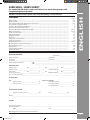
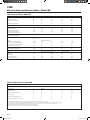
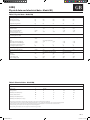
PR
O
-D
IA
LO
G
+
AQUASNAP
30RB / 30RQ
30RBY / 30RQY
Installation, operation and maintenance instructions
Cop_GB_.indd 1
13-06-2011 9:12:14
30RB/30RQ
30RBY/30RQY
Cop_GB_.indd 2
ENGLISH
Air-cooled liquid chillers and reversible cycle air-water heat pump with integrated hydronic module
13-06-2011 9:12:14
30RB/30RQ - 30RBY/30RQY
Air-cooled liquid chillers and reversible air-to-water heat pumps with
integrated hydronic module
Contents
Physical data......................................................................................................................................................................... Electrical data....................................................................................................................................................................... Dimensions and location of hydraulic connections.................................................................................................. User interface and main switch....................................................................................................................................... Clearance for horizontal outlet unit............................................................................................................................... Clearance for vertical outlet unit..................................................................................................................................... General information and hydronic module ................................................................................................................ Water connections.............................................................................................................................................................. Electrical connections........................................................................................................................................................ Refrigerant charge.............................................................................................................................................................. Electronic control................................................................................................................................................................ Start-up.................................................................................................................................................................................. Compressor replacement................................................................................................................................................. Pump replacement............................................................................................................................................................. Unit protection devices..................................................................................................................................................... Operating limits and operating range........................................................................................................................... General maintenance......................................................................................................................................................... Maintenance ........................................................................................................................................................................ Final recommendations..................................................................................................................................................... Troubleshooting.................................................................................................................................................................. Page
2-5
2-5
6-8
9
9
9
10-12
12-14
15
16
16
17
17
18
18-19
19
20
20
20
21
ENGLISH
For the use of the control system, refer to the Pro-Dialog + control manual.
Start-up check list
Start up date_ _________________________
Equipment sold by:_ _________________________________________________ Contract No:__________________________________
Installed by:_ _______________________________________________________ Contract No:__________________________________
Site address_____________________________________________________________________________________________________
Equipment type and serial No:
30RB_ ___________________________________________________________________
30RQ____________________________________________________________________
ELECTRICAL DATA:
Supply voltage
Ph 1:_ _______________V
Ph 2:_ _______________V
Ph 3:_________________V
Nominal voltage:_ _________________________________________ V
% network voltage_____________________________
Current draw
Ph 1:_ _______________A
Ph 2:_ _______________A
Ph 3:__________________A
Control circuit voltage:______________________________________ V
Control circuit fuse__________________________A
Main circuit breaker rating_________________________________________________________________________________________
PHYSICAL DATA
Coil:
Entering air temp.:_____________________________°C
Leaving air temp.:_ ____________________________°C
Plate heat exchanger:
Entering water temp.:_ _____________________ °C
Leaving water temp.:_______________________ °C
Loss of head (water):_______________________ kPa
SAFETY DEVICE SETTING:
High pressure switch: cut-out:___________________kPa
cut-in:_________________________ kPa
Oil level________________________________________________________________________________________________________
OPTIONS:
Commissioning engineer__________________________________________________________________________________________
Customer agreement
Name:______________________________________
Date:____________________________________
Note: Complete this start-up list at the time of installation.
GB - 1
128H68-GB.indd 1
13-06-2011 8:32:42
30RB
Physical data and electrical data - Model RB
Table I: Physical data - Model RB
30RB
017
021
026
033
Operating weight
with hydronic module
without hydronic module
Kg
Kg
189
173
208
193
255
237
280
262
Refrigerant charge R-410A
Kg
5,5
6,4
5,8
8,6
Compressor
One scroll compressor
Evaporator
One plate heat exchanger
Net water volume
l
1,52
1,9
1,71
2,28
Water connections (MPT gas)
inches
1
1
1-1/4
1-1/4
Maximum water pressure
kPa
1000
1000
1000
1000
(unit without hydronic module)
Maximum water pressure
kPa
400
400
400
400
(unit with hydronic module)
Hydronic module
Pump, mesh filter, expansion tank, flow switch, pressure gauges, automatic air purge valve and drain plug and safety
valve.
Pump
One single-speed pump
Water inlet connection (MPT gas) inches
1-1/4
1-1/4
1-1/4
1-1/4
Water outlet connection (MPT gas)
inches
1
1
1-1/4
1-1/4
Closed expansion tank water volume l
5
5
8
8
Pre-charge of expansion vessel
bar
1,5
1,5
1,5
1,5
Water fill system (option)
Inlet/outlet diameter (MPT gas)
inches
1/2
1/2
One, copper tubes and aluminium fins
Two,axial type with two speeds
495
495
3
3
2212
2212
870
870
Two-speed axial type
710
7
3530
900
710
7
3530
900
30RB
017
021
026
033
Power
V-ph-Hz
400-3-50
Voltage range
V
340-460
Starting current*
A
75
95
118
118
Maximum power drawn (Vn) ** kW
7,8
9,1
11,0
13,8
Condenser
Fan
Diameter
mm
No. of blades
Air flow (high speed)
l/s
Fan speed (high speed)
g/min
1/2
1/2
Table II: Electrical data - Model RB
Rated current***
A
8
12
16
17
Maximum power drawn (Vn) ****
A
13
16
20
24
Maximum power drawn (Vn +/-15%) †
A
15
18
23
27
* Max. starting current within the operation limits (corresponding to the current of locked rotor in the compressor)
** Input power when the unit is at its operation limits (evaporation temperature = 10°C, condensation temperature = 65°C) and at the rated voltage (400 V)
*** The currents shown refer to Eurovent conditions (evaporator water inlet and outlet temperature = 12/7°C with air to the condenser at 35°C)
**** Max. operating current related to the max. input power and rated voltage (400 V)
† Max. operating current related to the max. input power and within the range 340-460 V
GB - 2
128H68-GB.indd 2
13-06-2011 8:32:42
30RQ
Physical data and electrical data - Model RQ
E N G L I S H
Table I: Physical data - Model RQ
30RQ
017
021
026
033
Operating weight
with hydronic module
without hydronic module
Kg
Kg
206
191
223
208
280
262
295
277
Refrigerant charge R-410A
Kg
6,4
7,7
7,6
9,5
Compressor
One scroll compressor
Evaporator
One plate heat exchanger
Net water volume
l
1,52
1,9
2,28
2,85
Water connections (MPT gas)
inches
1
1
1-1/4
1-1/4
Maximum water pressure
kPa
1000
1000
1000
1000
(unit without hydronic module)
Maximum water pressure
kPa
400
400
400
400
(unit with hydronic module)
Hydronic module
Pump, mesh filter, expansion tank, flow switch, pressure gauges, automatic air purge valve and drain plug and safety
valve.
Pump
One single-speed pump
Water inlet connection (MPT gas) inches
1-1/4
1-1/4
1-1/4
1-1/4
Water outlet connection (MPT gas)
inches
1
1
1-1/4
1-1/4
Closed expansion tank water volume l
5
5
8
8
Pre-charge of expansion vessel
bar
1,5
1,5
1,5
1,5
Water fill system (option)
Inlet/outlet diameter (MPT gas)
inches
1/2
1/2
One, copper tubes and aluminium fins
Two,axial type with two speeds
495
495
3
3
2217
1978
870
870
Two-speed axial type
710
7
3530
900
710
7
3530
900
30RQ
017
021
026
033
Power
V-ph-Hz
400-3-50
Voltage range
V
340-460
Starting current*
A
75
95
118
118
Maximum power drawn (Vn) **
kW
7,8
9,1
11,0
13,8
Condenser
Fan
Diameter
mm
No. of blades
Air flow (high speed)
l/s
Fan speed (high speed)
g/min
1/2
1/2
Table II: Electrical data - Model RQ
Nominal current drawn***
kW
8
12
16
17
Maximum power drawn (Vn) ****
A
13
16
20
24
Maximum power drawn (Vn +/-15%) †
A
15
18
23
27
* Max. starting current within the operation limits (corresponding to the current of locked rotor in the compressor)
** Input power when the unit is at its operation limits (evaporation temperature = 10°C, condensation temperature = 65°C) and at the rated voltage (400 V)
*** The currents shown refer to Eurovent conditions (evaporator water inlet and outlet temperature = 12/7°C with air to the condenser at 35°C)
**** Max. operating current related to the max. input power and rated voltage (400 V)
† Max. operating current related to the max. input power and within the range 340-460 V
GB - 3
128H68-GB.indd 3
13-06-2011 8:32:42
30RBY
Physical data and electrical data - Model RBY
Table I: Physical data - Model RBY
30RBY
017
021
026
033
Operating weight**
with hydronic module
without hydronic module
209
193
228
213
255
237
280
262
5,8
8,6
Kg
Kg
Refrigerant charge R-410A
Kg
Compressor
5,5
6,4
One scroll compressor
Evaporator
One plate heat exchanger
Net water volume
l
1,52
1,9
1,71
2,28
Water connections (MPT gas)
inches
1
1
1-1/4
1-1/4
Maximum water pressure
kPa
1000
1000
1000
1000
(unit without hydronic module)
Maximum water pressure
kPa
400
400
400
400
(unit with hydronic module)
Hydronic module
Pump, mesh filter, expansion tank, flow switch, pressure gauges, automatic air purge valve and drain plug and safety
valve.
Pump
One single-speed pump
Water inlet connection (MPT gas) inches
1-1/4
1-1/4
1-1/4
1-1/4
Water outlet connection (MPT gas)
inches
1
1
1-1/4
1-1/4
Closed expansion tank water volume l
5
5
8
8
Pre-charge of expansion vessel
bar
1,5
1,5
1,5
1,5
Water fill system (option)
Inlet/outlet diameter (MPT gas)
inches
Condenser
Fan
Diameter
mm
No. of blades
Outlet static pressure
Pa
Air flow (high speed)
l/s
Fan speed (high speed)
g/min
1/2
1/2
One, copper tubes and aluminium fins
Two radial fans with backward blades
495
495
3
3
80
80
2212
2212
870
870
1/2
1/2
One axial fan
710
7
80
3530
900
710
7
80
3530
900
30RBY
017
021
026
033
Power
V-ph-Hz
400-3-50
Voltage range
V
360 - 440
Starting current*
A
75
95
118
118
Maximum power drawn (Vn) ** kW
8,0
9,3
11,2
14,0
Table II: Electrical data - Model RBY
Rated current***
W
8
12
20
21
Maximum power drawn (Vn) ****
A
13
16
20
24
Maximum power drawn (Vn +/-15%) †
A
15
18
23
27
* Max. starting current within the operation limits (corresponding to the current of locked rotor in the compressor)
** Input power when the unit is at its operation limits (evaporation temperature = 10°C, condensation temperature = 65°C) and at the rated voltage (400 V)
*** The currents shown refer to Eurovent conditions (evaporator water inlet and outlet temperature = 12/7°C with air to the condenser at 35°C)
**** Max. operating current related to the max. input power and rated voltage (400 V)
† Max. operating current related to the max. input power and within the range 360-440 V
GB - 4
128H68-GB.indd 4
13-06-2011 8:32:43
30RQY
Physical data and electrical data - Model RQY
E N G L I S H
Table I: Physical data - Model RQY
30RQY
017
021
026
033
Operating weight**
with hydronic module
without hydronic module
Kg
Kg
226
211
243
228
280
262
295
277
Refrigerant charge R-410A
Kg
6,4
7,7
7,6
9,5
Compressor
One scroll compressor
Evaporator
One plate heat exchanger
Net water volume
l
1,52
1,9
2,28
2,85
Water connections (MPT gas)
inches
1
1
1-1/4
1-1/4
Maximum water pressure
kPa
1000
1000
1000
1000
(unit without hydronic module)
Maximum water pressure
kPa
400
400
400
400
(unit with hydronic module)
Hydronic module
Pump, mesh filter, expansion tank, flow switch, pressure gauges, automatic air purge valve and drain plug and safety
valve.
Pump
One single-speed pump
Water inlet connection (MPT gas) inches
1-1/4
1-1/4
1-1/4
1-1/4
Water outlet connection (MPT gas)
inches
1
1
1-1/4
1-1/4
Closed expansion tank water volume l
5
5
8
8
Pre-charge of expansion vessel
bar
1,5
1,5
1,5
1,5
Water fill system (option)
Inlet/outlet diameter (MPT gas)
inches
1/2
1/2
One, copper tubes and aluminium fins
Two radial fans with backward blades
495
495
3
3
80
80
2217
1978
870
870
One axial fan
710
7
80
3530
900
710
7
80
3530
900
30RQY
017
021
026
033
Power
V-ph-Hz
400-3-50
Voltage range
V
360 - 440
Starting current*
A
75
95
118
118
Maximum power drawn (Vn) **
kW
8,0
9,3
11,2
14,0
Condenser
Fan
Diameter
mm
No. of blades
Outlet static pressure
Pa
Air flow (high speed)
l/s
Fan speed (high speed)
g/min
1/2
1/2
Table II: Electrical data - Model RQY
Nominal current drawn***
W
8
12
20
21
Maximum power drawn (Vn) ****
A
13
16
20
24
Maximum power drawn (Vn +/-15%) †
A
15
18
23
27
* Max. starting current within the operation limits (corresponding to the current of locked rotor in the compressor)
** Input power when the unit is at its operation limits (evaporation temperature = 10°C, condensation temperature = 65°C) and at the rated voltage (400 V)
*** The currents shown refer to Eurovent conditions (evaporator water inlet and outlet temperature = 12/7°C with air to the condenser at 35°C)
**** Max. operating current related to the max. input power and rated voltage (400 V)
† Max. operating current related to the max. input power and within the range 360-440 V
GB - 5
128H68-GB.indd 5
13-06-2011 8:32:43
30RB/30RQ - 30RBY/30RQY
Dimensions and location of hydraulic connections (mm)
Mod. 30RB 017 - 021
Mod. 30RQ 017 - 021
Fixing hole
Fixing hole
1 water inlet
2 water outlet
3 fill kit connection
4 safety valve outlet
5 electrical connections
1. Ingresso water
2. Uscita water
3. Uscita valvola di sicurezza 3/4” gas
1135
559
30
Mod. 30RBY 017 - 021
Mod. 30RQY 017 - 021
2
1
150
100
82
795
705
1570
100
155
120
600
651
50
28
1608
4
3
5
281
151.4
519
10
Fixing hole 10
660
Fixing hole
503.8
1 water inlet
2 water outlet
3 fill kit connection
4 safety valve outlet
5 electrical connections
1. Ingresso water
162
280 ext
31.9
584
2. Uscita water
3. Uscita valvola di sicurezza 3/4” gas
540 ext
GB - 6
128H68-GB.indd 6
13-06-2011 8:33:33
30RB/30RQ - 30RBY/30RQY
Dimensions and location of hydraulic connections (mm)
1185
580
1135
559
28
30
Mod. 30RBY 017 - 021xxA
Mod. 30RQY 017 - 021xxA
E N G L I S H
150
NUOVA100
82IMMAGINE
2
1
1476
1608
1476
795
705
100
5
281
151.4
50
280 ext
47
water inlet
water outlet
fill kit connection
safety valve outlet
electrical connections
50
540 ext
67
729
1185
307
Mod. 30RBY 017 - 021xxB
Mod. 30RQY 017 - 021xxB
1291
686
1135
30
559
2
1
28
1
2
3
4
5
660
Fixing hole ø 10
162
357
503.8 100
519
Fixing hole ø 10
31.9
584
594
76
155
120
651
600
50
28
1570
4
3
150
100
82
1476
1608
1476
100
5
584
700
47
156
water inlet
water outlet
fill kit connection
safety valve outlet
electrical connections
156
280 ext
1
2
3
4
5
281
151.4
357
100
503.8
519
Fixing hole ø 10
31.9
660
NUOVA 162
IMMAGINE
Fixing hole ø 10
76
155
120
795
705
651
600
50
28
1570
4
3
540 ext
307
729
1291
67
GB - 7
128H68-GB.indd 7
13-06-2011 8:35:16
30RB/30RQ - 30RBY/30RQY
Dimensions and location of hydraulic connections (mm)
Mod. 30RB 026 - 033
Mod. 30RQ 026 - 033
760
1790
995
153
263
148
710 (Fixing hole ø 10)
824
1
2
3
4
129
745 (Fixing hole ø 10)
1002
129
115
357
50
170
460
170
water inlet
water outlet
automatic fill kit connection (optional)
electrical connections
Mod. 30RBY 026 - 033
Mod. 30RQY 026 - 033
Fixing hole
1
2
3
4
Fixing hole
water inlet
water outlet
automatic fill kit connection (optional)
electrical connections
GB - 8
128H68-GB.indd 8
13-06-2011 8:35:35
30RB/30RQ - 30RBY/30RQY
User interface and main switch
E N G L I S H
Service door
User interface*
User interface*
Service door
Disconnector
Disconnector
* Check that the user interface is protected as described in section “Electronic control”.
Clearances (mm) for horizontal outlet unit
(30RB-30RQ017-021)
Clearances (mm) for vertical outlet unit
(30RB-30RQ026-033)
200 mm
500 mm
700 mm
200 mm
400 mm
200 mm
300 mm
700 mm
500 mm
200 mm
400 mm
300 mm
400 mm
200 mm
400 mm
400 mm
400 mm
500 mm
200 mm
200 mm
400 mm
200 mm
1800 mm
200 mm
1000 mm
200 mm
1000 mm
For units with a variable speed pump, leave a suitable space for easy access to
the driver. To reach the driver, remove the rear or side right panel of the unit.
GB - 9
128H68-GB.indd 9
13-06-2011 8:36:20
30RB/30RQ - 30RBY/30RQY
General information and hydronic module
Unit installation
Read this manual thoroughly before starting machine installation.
The device complies with the low voltage directives, Machinery
Directive and EMC Directive.
• The installation must be carried out by a qualified installer.
• Follow all current national safety code requirements. In particular
ensure that a properly sized and connected ground wire is in place.
• Check that voltage and frequency of the mains power supply are
those required; the available power must be adequate to operate any
other possible appliances connected to the same line. Also ensure that
national safety code requirements have been followed for the mains
supply circuit.
• After installation thoroughly test the system operation and explain all
system functions to the owner.
• Leave this manual with the owner for consultation during future
periodic maintenance.
• Be sure the unit and its components are checked periodically to look
for loosen, damaged or broken components. In case of persisting
defects, the unit may cause personal injury or property damage.
IMPORTANT :
During the unit installation make first the hydronic connections
and then electrical connections. If unit is uninstalled first disconnect
electrical cables, then the hydronic connections.
CAUTION :
Disconnect the mains power supply switch before servicing the
system or handling any internal parts of the unit.
• The manufacturer declines any liability for damage resulting from
Installation instructions for ductable units
Units 30RBY and 30RQY (ductable unit ) can be installed in buildings and
connected by means of duct systems
- on the outside air inlet side (only units size 17-21 kW)
- on the fan side where the air is released after passing through the air/
refrigerant exchanger.
Therefore the unit can be installed in a building without changing the
indoor air temperature.
These units are designed for a static pressure of 80 Pa: for this
reason, the friction loss of any intake duct added up to the friction
loss of the supply duct must not exceed the indicated value. For
units size 17-21 kW: if the units are not provided with a supply duct,
a protective grille must be installed to prevent access to fans.
Unit with optional intake filters (size 17 -21 kW).
Access to filters for maintenance of units 17 and 21 kW is possible by
removing the screws on the filter support side.
After removing the screws remove the closing panel.
Remove the filters on the unit back side as shown below.
The friction loss of the filters with nominal air flow is 7 Pa.
Check the filter is clean every two or three months (more often if the
unit is installed in a dusty place) and when the friction loss is twice the
nominal value.
A dirty filter causes a decrease in air flow and in the unit efficiency.
The filter should be cleaned with air (not water) as it is made of
aluminium.
Fan supply
The standard ducted units are supplied with a rectangular flange.
It is advisable to connect the supply duct by interposing a flexible joint
to avoid vibrations and noise are transmitted to the building structure.
Do not use ducts with a weight exceeding 10 kg to avoid damages to
the unit.
modifications or errors in the electrical or hydronic connections.
• Failure to observe the installation instructions or use of the unit under
conditions other than those indicated in Tables.
“Operating limits”, will immediately void the unit warranty.
• Failure to observe electric safety codes may cause a fire hazard in case
of short circuits.
• Do not install or use damaged units. Do not install or use damaged
units.
• During unit operation, some of the refrigerant circuit elements could
reach a temperature in excess of 70°C so only trained and qualified
personnel should access areas protected by access panels.
• In case of any malfunctioning turn the unit off, disconnect the mains
power supply and contact a qualified service engineer.
• All of the manufacturing and packaging materials used for your
new appliance are compatible with the environment and can be
recycled.
• Dispose of the packaging material in accordance with local
requirements.
• This equipment contains refrigerant R-410A that must be disposed of
in a proper manner. When disposing of the unit after its operational
life, remove it carefully. The unit must then be delivered to an
appropriate disposal center or to the original equipment dealer.
• Carefully recover refrigerant within this unit before final disposal or
when servicing. Never vent refrigerant to atmosphere.
Choosing the installation site
• This unit should not be installed in an explosive atmosphere.
• The unit can operate in normal radioelectric atmospheres in
residential, commercial and light industrial installations. For other
applications, please consult Carrier.
• In the case of heat pump operation with an outdoor temperature of
less than 0 °C the unit must be installed at least 300 mm above ground
level. This is necessary to prevent ice from accumulating on the frame
and to permit correct operation also in the event of heavy snowfalls.
The unit must be levelled on both axes ( the tolerance is less than 2
mm per metre ).
• In some cases it may be necessary to fit deflectors against strong
winds and to stop snow from hitting the coil directly. These deflectors
must be installed so that the normal air circulation is not obstructed.
2
3
1
3
2
1
3
3
GB - 10
128H68-GB.indd 10
13-06-2011 8:36:27
30RB/30RQ - 30RBY/30RQY
General information and hydronic module
Make sure all intake inlets and air outlets are free from any obstacle
(such as an open door).
Auxiliary condensate drain pan
During the heat pump operation, it might be necessary to drain up to
15 l of condensate.
On demand, Carrier may supply an optional condensate drain pan to be
placed under the unit. The corresponding codes are 30RB9003 (for units
17 – 21 kW) and 30RB9004 (for units 26 – 33 kW).
The pan must then be connected to the condensate drainage system
by means of a ø 16 mm vinyl pipe (use the condensate drainage
connection supplied with the pan).
On sizes 26- 33 kW, it is possible to disconnect the end of the
condensate drain pipe which is fixed to the rear panel and convey the
condensate water from the heat exchanger to the auxiliary pan.
When installing the pan, make sure it is levelled and that the
condensate water from the unit is discharged correctly.
Siting the unit
Check that:
- The location is able to support unit operating weight (Table I).
- There is sufficient space for servicing and air flow around the unit (see
“Clearances”figure).
- The selected site is without dust or foreign material which could
obstruct the coil.
- When installing the unit on the ground, the selected site is not subject
to flooding.
- The installation is in accordance with local rules and standards
governing the installation of air conditioning equipment.
- Vibration absorbers have been provided throughout the installation to
prevent noise from being transmitted.
- To avoid possible damages (in particular to sizes 26-33 kW) fix the
vibration absorbers under a feet-supporting frame of the unit.
E N G L I S H
Transport
1. Use spreader bars to lift the unit to avoid damage to the panels.
Avoid violent movements.
2. Never roll or swing the unit more than 15°.
IMPORTANT:
Ensure that all unit panels are fixed in place before moving the unit.
Raise and set down the unit carefully.
IMPORTANT:
Always ensure that the unit is levelled correctly.
Condensate pan
Connection
GB - 11
128H68-GB.indd 11
13-06-2011 8:36:32
30RB/30RQ - 30RBY/30RQY
General information and hydronic module
Hydronic module
Hydronic module for unit 30RB/30RQ026-033
The hydronic module is factory-installed.
This eliminates the need to install the necessary components
on-site, making the unit more compact and easy to install.
1
4
Hydronic module for unit 30RB/30RQ017-021
7
1
4
6
2
8
1 automatic purge
2 pressure gauge for
hydraulic circuit static
pressure
3 hydronic module drain
valve
4 hydronic module pump
5 safety valve
6 flow switch
7 expansion vessel
8 mesh filter
9 pressure reducer (optional)
10 on/off valve
(optional)
2
5
IN
9
6
7
10
IN
OUT
OUT
3
IN
8
5
1 automatic purge
2 pressure gauge for
hydraulic circuit static
pressure
3 hydronic module drain
valve
4 hydronic module pump
5 safety valve
6 flow switch
IN
3
9
10
7 expansion vessel
8 mesh filter
9 pressure reducer (optional)
10 on/off valve (optional)
Units with variable speed pump
In this type of unit, water flow is not controlled through a nominal value
In fact, it is controlled by changing the pump rotation speed to maintain
a water thermal head (by default) or a water outlet pressure according
to the user preset value.
The control parameter is detected by temperature sensors placed at the
water inlet and outlet of the unit (by default) or by a pressure sensor
installed on the water outlet of the unit.
The control system detects the temperature difference from the sensors
(by default) or the pressure detected by the sensor installed on the
outlet and compares it to the value the user has preset to adjust the
pump rotation speed as follows:
•If the temperature difference (by default) is greater than the setpoint
or the detected pressure is lower than the setpoint, pump speed and
flow rate are increased.
•If the temperature difference (by default) is lower than the setpoint or
the detected pressure is greater than the setpoint, pump speed and
flow rate are decreased.
Flow rate is modified considering the maximum and minimum flow
rates allowed for the unit as well as the maximum and minimum supply
rate of the pump.
In case that alarms occur during start-up, refer to the control manual.
Typical diagram of hydronic circuit with hydronic module 17-21kw
23
14
15
2
17
5
21
16
25 18
19
20
24
16
25 18 19
11
1
6
21
7
10
13
3
4
22
9
12
8
26
27
--- Hydronic module (units with hydronic module)
- - - - Water supply automatic system (optional)
GB - 12
128H68-GB.indd 12
13-06-2011 8:36:39
30RB/30RQ - 30RBY/30RQY
Water connections
E N G L I S H
Typical diagram of hydronic circuit
with hydronic module 26-33kw
23
14
15
17
21
16
25 18
19
25 18 19
5
2
11
7
20
24
16
1
3
21
22
13
9
4
6
26
10
12
8
27
--- Hydronic module (units with hydronic module)
- - - - Water supply automatic system (optional)
LEGEND
HYDRONIC COMPONENTS
1 Mesh filter
2 Expansion tank
3 Safety valve
4 High pressure pump
5 Breather
6 Water drain valve
7 Flow sensor
8 Leaving temperature sensor from refrigerant - water exchanger
9 Entering temperature sensor from refrigerant - water exchanger
10 Pressure gauge
11 Plate heat exchanger
12 Anti-freeze electric heater for refrigerant - water exchanger
13 Anti-freeze electric heater for pipes
14 On/off valve ( automatic system for water filling- optional)
15 Pressure reducer (automatic system for water filling- optional)
Make the plate heat exchanger hydraulic connections with the
necessary components, using material which will guarantee that the
screwed joints are leakproof. The typical hydraulic circuit diagram shows
a typical water circuit installation in an air conditioning system.
For an application with a water circuit, the following recommendations
must be taken into account:
1. The pump must be fitted immediately before of the heat exchanger
and after the connection to the system return (unit without hydronic
module).
2. It is advisable to install shut-off valves to allow isolation of the
most important circuit components, as well as the heat exchanger
itself. These valves (ball, globe or butterfly valves) should produce a
minimum loss of charge when they are open.
3. Provide unit and system drains and vents at the lowest system point.
4. Install purges in the higher sections of the installation.
5. Pressure ports and pressure gauges should be installed upstream
and downstream of the water pump (unit without hydronic module).
6. Thermometers should be installed in the unit water inlet and outlet.
7. All piping must be adequately insulated and supported.
Installation of the following components is obligatory:
1. The presence of particles in the water can lead to obstructions in the
heat exchanger.
It is therefore necessary to protect the heat exchanger inlet with an
extractable mesh filter. The filter mesh gauge must be at least 10
mesh/cm2.
The equipment standard version with hydronic module is equipped
with mesh filter, included in the supply and installed.
2. After assembling the system, or repairing the circuit, the whole
system must be thoroughly cleaned with special attention paid to
the state of the filters.
3. Pump flow rate control is made through a flow control valve supplied
SYSTEM COMPONENTS
16 Pocket for temperature sensor
17 Breather
18 Flexible connections
19 On/Off valve
20 Mesh filter (compulsory if the unit is not equipped with hydronic module)
21 Pressure gauge
22 Water flow control valve (factory supplied but to be installed on site)
23 Charge valve
24 Bypass valve for anti-freeze protection (when, in winter, on/off valves are
closed)
25 Pressure sensor
26 Water drain valve from the plant
27 Water drain valve from refrigerant-water exchanger
with the unit with hydronic module, which must be installed on the
delivery pipe during installation.
4. When water has to reach temperatures below 5°C, or the equipment
is installed in areas subject to temperatures below 0°C, it is necessary
to mix water with glycol in suitable quantity.
The maximum amount of ethylene and propylene glycol allowed is
40%.
Frost protection
Frost protection of the plate heat exchanger and of the circuit inside the
hydronic module is always guaranteed down to -10°C by the electric
heaters that are automatically activated if needed. The power supply
to the electric heaters of the plate heat exchanger and to the internal
circuit of the hydronic module must never be interrupted.
IMPORTANT: Both the unit main switch (1Q) and the auxiliary
switch (2Q) must always be set in cut-in position (positions 1Q
and 2Q are shown on the electric diagram).
GB - 13
128H68-GB.indd 13
13-06-2011 8:36:40
30RB/30RQ - 30RBY/30RQY
Water connections
Water pressure drop of the unit without hydronic module
110
1
100
2
3
4
5
90
80
Pressure drop , kPa
70
60
50
40
30 di pressione , kPa
Caduta
20
10
0
0,0
0,5
1,0
1,5
2,0
Water flow rate, l/s
Legend
1. 30RB-RQ017
2. 30RB-RQ021
3. 30RB026
4. 30RB033-RQ026
5. 30RQ033
Outlet available static pressure of the unit with hydronic module
Available static pressure, kPa
300
290
280
270
260
250
240
230
220
210
200
190
180
170
160
150
140
130
120
Pressione
statica utile, kPa
110
100
90
80
70
60
50
0,0
0,5
3
2
1
5
4
1,0
1,5
Water flow rate, l/s
2,0
2,5
Legend
1. 30RB-RQ017
2. 30RB-RQ021
3. 30RB026
4. 30RB033-RQ026
5. 30RQ033
GB - 14
128H68-GB.indd 14
13-06-2011 8:36:41
30RB/30RQ - 30RBY/30RQY
Electrical connections and refrigerant charge
Electrical connections
Liquid refrigerant charge
CAUTION:
To prevent electrical shock or equipment damage, make sure
disconnects are open before electrical connections are made.
Checking the charge
Power supply cable size and external connection must be made by
the installer according to the unit installation characteristics and the
applicable standards. The power supply and earth multicore cable of
the device has to be connected to the general disconnector by routing
the cable through the grommet installed in the device, after removing the
access panel/s. The maximum section allowable for flexible copper cable
is 25 mm2. Before connection, check that phase sequence
L1 – L2 – L3 is correct. The table below should be considered as a
reference and does not involve Carrier responsibility.
30RB/30RQ
017
Unit
Cable section
30RB/30RQ
021
5 x 2,5 mm2
Power supply cable
Fuse (type "gG")
30RB/30RQ
026
30RB/30RQ
033
5 x 4 mm2
H07 RN-F
25 A
32A
40 A
50 A
Take special care when making the earth connection.
The maximum permitted voltage and current imbalance is 10% of
the values indicated in Table II. Contact your local power company for
correction of an incorrect line voltage.
CAUTION:
Operation of the unit on improper line voltage constitutes abuse and is
not covered by the Carrier warranty.
IMPORTANT:
To ensure the correct unit power supply (cable entry, conductor cross
section, protection devices etc.), consult the electrical data table, the
wiring diagram supplied with the unit and the applicable standards
concerning the installation of air conditioning equipment.
Never operate a unit if the voltage imbalance exceeds 2%. The
following formula must be used to determine the percentage of voltage
imbalance.
Voltage imbalance (%) =
Largest deviation from average voltage x 100
———————————————————————————Average voltage
Example:
Supply voltage: 400-3-50
AB =
BC =
AC =
404 V
399 V
394 V
Average voltage = 404 + 399 + 394
3
Motor
= 399 ≈ 400 V
Determine maximum deviation from average voltage:
AB =
BC =
AC =
404 - 400 = 4
400 - 399 = 1
400 - 394 = 6
Largest deviation is 6 volts. Percentage voltage imbalance is therefore:
6
400
x 100 = 1,5 %
E N G L I S H
CAUTION:
When adjusting the refrigerant charge always ensure that water
is circulating in the heat exchanger to prevent any possibility of
freezing up. Damage caused by freezing is not covered by the
product warranty.
30RB-RQ units are shipped with a full operating charge of refrigerant.
Refer to Table I.
If it is nevertheless necessary to add more refrigerant, run the unit for
some time in cooling mode and then slowly add liquid refrigerant into
the suction side until there are no bubbles in the sight glass.
30RB-RQ units use a R-410A refrigerant charge. For your information,
we are reproducing here some extracts from the official publication
dealing with the design, installation, operation and maintenance
of air conditioning and refrigeration systems and the training of
people involved in these activities, agreed by the air conditioning and
refrigeration industry.
Refrigerant guidelines
Refrigeration installations must be inspected and maintained regularly and
rigorously by specialists. Their activities must be overseen and checked
by properly trained people.
To minimise discharge to the atmosphere, refrigerants and lubricating
oil must be transferred using methods which reduce leaks and losses to
a minimum.
• Leaks must be repaired immediately.
• Service valves fitted to the flow and return lines permit charge transfer
to a suitably arranged external container.
• It is indispensable to use a dedicated transfer station.
• Compressor lubricating oil contains refrigerant. Any oil drained from a
system during maintenance must therefore be handled and stored
accordingly.
• Refrigerant under pressure must never be discharged to the
atmosphere.
Recharging liquid refrigerant
R-410A refrigerant operates at 50%-70% higher pressures than R-22.
Be sure that servicing equipment and replacement components are
designed to operate with R-410A.
The cylinders that contain R-410A are pink.
The cylinders that contain R-410A are provided with a dip tube that
allows fluid to escape from the cylinder both when in upright position
and when turned upside down.
Unit R-410A should be charged with liquid refrigerant. Apply a common
flow regulator available on the market to the hose pipe to vaporize the
liquid refrigerant before it enters the unit.
R-410A, like other HFCs, is only compatible with the oils selected by the
manufacturer of compressors(POE).
NOTE:
Regularly carry out leak checks and immediately repair any leak found.
Undercharge
CAUTION:
The installer must install protection devices, as required by the
applicable legislation.
If there is not enough refrigerant in the system, this is indicated by gas
bubbles in the moisture sight glass.
There are two possibilities:
For sizes 17-21 kW, the power supply cable must be routed through the
grommet of the electric control panel. To connect the power supply
cable to the main disconnector remove the metal protection box (by
removing the two fixing screws). After completing all connections,
re-install the protection box by fixing the two screws which were
previously removed.
The pressure gauge and the liquid level gauge can be checked by
removing the plugs from the side panel (there is no need to remove the
whole panel).
• Small undercharge (bubbles in the sight glass, no significant change in
suction pressure); in this case:
- After detection and repair the unit can be recharged.
- The replenishment of the charge must always be done in the
cooling mode, slowly introducing liquid refrigerant at the suction
side, until there are no bubbles in the sight glass.
GB - 15
128H68-GB.indd 15
13-06-2011 8:36:41
30RB/30RQ - 30RBY/30RQY
Refrigerant charge and electronic control
• Significant undercharge (large bubbles in the sight glass, significant
drop in suction pressure). In this case:
- Completely drain the refrigerant charge, using a refrigerant recovery
unit.
After detection and repair check the charge with the unit off, drain
the system and recharge the full amount of liquid refrigerant (see
Table I) on the suction and discharge side.
- The refrigerant container used must contain a minimum of 10% of
its initial charge.
operation at low fan speed (e.g. during the night).
This option also permits cascade operation of two units and remote
control via communication bus (RS 485 serial port).
CAUTION:
If brazing is to be done, the refrigerant circuit must be filled with
nitrogen.
Combustion of refrigerant produces toxic phosgene gas.
IMPORTANT:
Never use the compressor as a vacuum pump.
Always add refrigerant via the suction line.
Refrigerant must be added very slowly.
Do not overcharge the system with refrigerant.
Electronic control
Operation and control of all units is carried out via the electronic control.
The instructions supplied with the control include comprehensive
descriptions.
After use, check the user interface is properly inserted into its housing
and the cover is closed by means of the screw supplied. This way, the
electronic control and the unit are protected against any impacts and
atmospheric agents.
PRO-Dialog + electronic control
PRO-DIALOG + is an advanced numeric control system that combines
complex intelligence with great operating simplicity.
PRO-DIALOG + constantly monitors all machine parameters and safety
devices, and precisely manages the operation of compressor and fans
for optimum energy efficiency.
It also controls the operation of the water pump.
A powerful control system
The PID control algorithm with permanent compensation for the
difference between entering and leaving water temperature and
anticipation of load variations regulates compressor operation for
intelligent leaving water temperature control.
To optimise power absorption, the PRO-DIALOG + automatically recalibrates the set point of the entering water temperature based on
the outside air temperature to one of the two pre-set values (occupied
building and of an unoccupied building for example).
PRO-DIALOG + control is auto-adaptive for full compressor protection.
The system permanently optimises compressor run times according to
the application characteristics (water loop inertia), preventing excessive
cycling.
In most comfort air conditioning applications this feature makes a buffer
tank unnecessary.
Clear and easy-to-use control system
The operator interface is clear and user-friendly: two LEDs and digital
displays allow the immediate control of the device operating data.
The menus offer direct access to all machine controls, including a history
of possible faults, for rapid and complete chiller fault diagnosis.
Extended communications capabilities
PRO-DIALOG + allows remote control and monitoring of the unit
through a wired connection: 7-8 x 0.5 mm² multiple cables. The cable
should be screened of the FROH2R or BELTEN 9842 type. The screening
should be grounded only on the electric unit panel board.
Functions available are start/stop, cooling/heating mode selection (only
30RQ unit), power demand limit or dual set-point and customer safety
lock.
The system permits remote signalling of any general anomaly for each
refrigerant circuit.
Three independent time schedules permit definition of: chiller start/
stop, operation at the second set-point (e.g. unoccupied mode), and
GB - 16
128H68-GB.indd 16
13-06-2011 8:36:41
30RB/30RQ - 30RBY/30RQY
Start-up, compressor replacement
E N G L I S H
Start-up
Compressor replacement
Unit start-up is done by the electronic control described above, and
must always be carried out under the supervision of a qualified air
conditioning engineer.
As the compressors are hermetic, when an internal fault occurs, the
compressor must be replaced.
For sizes 26 and 33, access to the oil level gauge is possible by removing
the 6 screws of the electric box.
This must be done as detailed below:
Necessary checks/precautions before start-up
- Ensure that all electrical connections are properly tightened.
- Ensure that the unit is level and well-supported.
- Check that the hydraulic circuit has sufficient water flow and that the
pipe connections correspond to the installation diagram.
- Ensure that there are no water losses. Check the correct operation of
the valves installed.
- All panels should be fitted and firmly secured with the corresponding
screws.
- Make sure that there is sufficient space for servicing and maintenance
purposes.
- Ensure that there are no refrigerant leaks.
- Confirm that the electrical power source agrees with the unit
nameplate rating, wiring diagram and other documentation for the
unit.
- Ensure that the power supply corresponds to the applicable standards.
- Make sure that compressors float freely on the mounting springs.
- Disconnect the unit from the electrical supply.
- Remove the access panels.
- Remove the gas from the refrigerant circuit using recovery equipment
to avoid harming the atmosphere.
- Electrically disconnect the compressor.
- Unbraze or unscrew the suction and discharge lines, taking care not to
damage the rest of the components.
- Remove the compressor fastenings.
- Replace the compressor, ensuring that it contains sufficient oil.
- Braze or screw in the lines.
- Connect the compressor according to the wiring diagram.
- Evacuate the compressor.
- Introduce the quantity of refrigerant indicated on the nameplate
through the service couplings located on the high and low pressure
side.
NOTE:
This operation must be carried out by a qualified person.
Shift the electric box to allow access to the oil level gauge.
Screws to be removed
GB - 17
128H68-GB.indd 17
13-06-2011 8:36:44
30RB/30RQ - 30RBY/30RQY
Pump replacement, unit protection devices
Table III: Pressure switch settings
Pump replacement
If the water pump needs to be replaced, proceed as follows:
- Disconnect the unit from the power supply.
- Open/remove the access panel/s
- Electrically disconnect the pump.
- Empty all water from the hydronic module.
- Loosen the pipe unions 1 and 3.
- Remove the four pump fixing screws 2.
- Replace the pump.
- Fit the pump fixing screws 2.
- Tighten the pipe unions 1 and 3.
- Electrically connect the pump.
- Connect the unit to the power supply.
- Make sure the pump rotates in the right direction using the hole in the
back panel.
- Reinstall the lateral access panel.
Cut-out
44 bar
High pressurestat Reset
Manual
CAUTION: Alteration of factory settings other than the design set-point,
without manufacturer's authorisation, may void the warranty. In case of
use other than the manufacturer configuration, Carrier Service must be
asked for permission to change the Pro-Dialog + system configuration.
Operating limits 30RB
These units have been designed to operate within the following limits:
Evaporator
Minimum °C Maximum °C
Water entering temp. (at start-up)
7,8*
Water leaving temp. (in operation)
5**
Condenser
30
18
Air entering temperature
48
-10
Operating limits 30RQ
Cooling cycle
1
Plate heat exchanger
Minimum °C Maximum °C
Water entering temp. (at start-up) 7.8*
30
Water leaving temp. (in operation)
5**
18
Coil:
Air entering temperature
-10
48
Heating cycle
Plate heat exchanger
Water entering temp. (at start-up) Water leaving temp. (in operation)
Coil:
Plate heat exchanger
Minimum °C
10
20
Minimum °C
-15
*
**
1 pipe union
2 screw
3 pipe union
2
3
Description of unit protection devices
The unit includes the following protection devices:
- Internal compressor protection.
- Fan motor internal thermal protection.
- Main switch.
- Anti-short-cycle protection.
- Thermomagnetic main switch.
- Thermomagnetic control switch.
- Fan circuit breaker, heaters and compressor.
- Defrost thermostat.
- Fault detector for the temperature and pressure sensors.
- High pressurestat: this protects the unit against excessive condensing
pressure.
The high pressurestat has factory-fixed non-adjustable settings.
The appliance stops due to the intervention of the high pressure alarm
threshold, before the high pressurestat intervenes. This function is
performed by the electronic control device via a pressure transducer.
- Low pressurestat: This function is performed by the electronic control
device via a pressure transducer.
Only on appliances with hydronic module.
- Pump motor external thermal protection.
Maximum °C
45
50
Maximum °C
40
Contact Carrier if an entering water temperature lower than 7.8 °C is necessary
”
If glycol is used but leaving water temperatures are greater than 5°, select option
"medium brine" by the user interface. UI by selecting the "medium brine"
If you are using but the glycol outlet temperature is greater than 5 ° C, you must
select the user interface option "medium brine"
Minimum and maximum water flow rates in the
plate heat exchangers
30RB-RQ017
30RB-RQ021
30RB026
30RQ026
30RB033
30RQ033
Minimum flow
rate, l/s
Maximum flow
rate, l/s*
Maximum flow
rate, l/s**
0,45
0,57
0,67
0,67
0,87
0,87
1,4
1,6
2
2,2
2,2
2,3
1,3
1,5
1,5
1,8
1,8
1,9
*
Maximum water flow rate with an available static pressure of 50 kPa (units with
hydronicmodule)
** Maximum water flow rate at a plate heat exchanger pressure drop of 100 kPa
(units without hydronic module)
Water circuit water content
Whatever the size of the system, the minimum content of the water
circuit is given by the following formula:
Content = CAP(kW) x N = Litres
where CAP is the nominal system capacity (kW) at nominal operating
conditions of the installation.
Application
Air conditioning
Industrial process cooling
N
3,5
See note
The water content is necessary to ensure the stability of plant operation
and accurate temperature control. It is often necessary to add a buffer
water tank to the circuit in order to achieve the required volume.
NOTE:
For industrial process cooling applications, where high stability of
GB - 18
128H68-GB.indd 18
13-06-2011 8:36:45
30RB/30RQ - 30RBY/30RQY
Unit protection devices, operating limits and operating range
water temperature levels must be achieved, the values above must
be increased.
We recommend consulting the factory for these particular
applications.
Operating range - 30RB units
53
48
The units provided with hydronic module are supplied with an
expansion vessel to limit the water content of the hydraulic circuit. The
table below shows the maximum content of water and a mix of water/
ethylene glycol of the hydraulic circuit.
026 - 033
bar
1,5
3
1,5
3
Water
litri
200
50
350
140
GE 10%
litri
150
38
263
105
GE 20%
litri
110
28
193
77
GE 30%
litri
90
23
158
63
GE 40%
litri
75
19
131
53
38
33
28
23
18
13
8
3
-2
-7
-12
-4
-2
0
2
4
6
8
10
12
14
16
18
Leaving water temperature °C
20
22
24
Operating range - 30RQ units
53
48
43
Entering air temperature °C
017 - 021
Static pressure
43
Entering air temperature °C
Maximum water content of hydraulic circuit
30RB-30RQ
E N G L I S H
GE: ethylene glycol
38
33
28
23
18
13
8
3
-2
-7
-12
-4
-2
0
2
4
6
8
10
12
14
16
Leaving water temperature °C
18
20
22
24
45
40
Entering air temperature °C
35
30
25
20
15
10
5
0
-5
-10
-15
-20
15
20
25
30
35
40
45
50
55
Leaving water temperature °C
Note:
Operating range with anti-freeze solution and with special configuration
of the Pro-Dialog control system
GB - 19
128H68-GB.indd 19
13-06-2011 8:36:45
30RB/30RQ - 30RBY/30RQY
General maintenance, maintenance and final recommendations
General maintenance
CAUTION: Before starting any servicing or maintenance operation on
the unit, make sure that the power supply has been disconnected. A
current discharge could cause personal injury.
- Controls:
Check the operation of all the electrical components, the high
pressurestat and of the high and low pressure transducers and the
water, air and defrost temperature detector.
In order to obtain maximum performance from the unit special
attention should be paid to the following points:
Maintenance
- Electrical connections:
The supply voltage should be within the limits indicated in Table II.
Ensure that no faulty contacts exist in the terminal blocks, contactor
boards, etc. Make sure that all the electrical connections are properly
tightened, and that all the electrical components (contactors, relays,
etc) are firmly secured to the corresponding rails. Pay special attention
to the condition of the connecting cables between the control
elements and the electrical box, and to that of the unit power supply
cable. They should not be twisted and there should be no slits or
notches in the insulation.
Check that the starting and running consumptions are within the
limits specified in Table II.
- Water connections:
Make sure there are no water leaks from the system. Should the unit
be shutdown for long periods, open the drain valve installed on the
hydronic module and partially drain the pump and the water pipes
as well as the drain valve on the plate-type exchanger, which must
be installed on the hydraulic circuit. To completely drain the pump,
remove the cap on it. This operation is essential if temperatures are
expected to drop below freezing. If the unit is not drained, the main
switch should remain connected so that the defrost thermostat can
operate. Carefully clean the system water filter.
- Plate heat exchanger cleaning:
In some applications, for example when very hard water is used, there
is an increased tendency for fouling. The heat exchanger can always be
cleaned by circulating a cleaning fluid.
A weak acid solution should be used (5% phosphoric acid or, if
frequently cleaned 5% oxalic acid), and the cleaning fluid should be
pumped through the exchanger.
The tank installation can be permanent or, alternatively, the connections
can be prepared and, at any given time, a portable cleaning device can
be connected.
To achieve optimum cleaning the acid solution should be circulated
at a minimum of 1.5 times the normal operational flow speed, and
preferably in reverse direction. The installation should then be flushed
with large amounts of water to totally remove the acid before the
system is started up.
Cleaning should be done at regular intervals and should never be left
until the unit has become blocked. The time intervals between cleaning
depend on the quality of the water used, but as a general rule it is
advisable to clean it at least once a year.
- Refrigerant circuit:
Ensure that there is no leakage of refrigerant or oil from the
compressor. Check that the high and low side operating pressures are
normal. Check the cleanliness of the refrigerant-water heat exchangers
by checking the pressure drop across them.
Servicing recommendations
- Maintenance of the unit must be carried out by skilled personnel
only. Nevertheless, the easiest operations, such as cleaning of the
battery and the unit external parts can be carried out by non-skilled
personnel.
- For any operation on the unit follow thoroughly the instructions
shown in the manual and on the unit labels as well as the Safety
Standards.
Always wear the protective gloves and safety glasses. Pay attention to
burns when brazing.
- Use only Carrier Original Spare Parts when repair is required. lways
make sure the spare parts are installed correctly. Always install the
spare parts in the original position.
- Before replacing any of the elements in the cooling circuit, ensure that
the entire refrigerant charge is removed from both the high and low
pressure sides of the unit.
- The control elements of the cooling system are highly sensitive. If they
need to be replaced, care should be taken not to overheat them with
blowlamps whilst soldering. A damp cloth should be wrapped around
the component to be soldered, and the flame directed away from the
component body.
- Silver alloy soldering rods should always be used.
- If the total unit gas charge has to be replaced, the quantity should be
as given on the nameplate and the unit should be properly evacuated
beforehand.
- During unit operation all panels should be in place, including the
electrical box access panel.
- If it is necessary to cut the lines of the refrigerant circuit, tube cutters
should always be used and never tools which produce burrs. All
refrigerant circuit tubing should be of copper, specially made for
refrigeration purposes.
Final recommendations
The unit you have purchased has undergone strict quality control
procedures before leaving the factory. All components, including the
control systems and electrical equipment, etc., are certified by our
Quality Control Department, and tested under the harshest possible
operating conditions in our laboratories. However, after leaving the
factory, it is possible that one or more of these elements may be
damaged due to causes beyond our control. In such an event, the user
should not work on any of the internal components, or subject
the unit to operating conditions which are not specified in this
manual, since serious damage may result and the guarantee would
be invalidated. Repair and maintenance work should always be left to
the installer.
All recommendations concerning unit installation are intended as a
guideline. The installer should carry out the installation according to the
design conditions and should comply with all applicable regulations for
air conditioning and refrigeration installations.
NOTE: The manufacturer does not accept responsibility for any
malfunctions resulting from misuse of the equipment.
Tank installation
Weak acid
solution tank
Heat exchanger
GB - 20
128H68-GB.indd 20
13-06-2011 8:36:46
30RB/30RQ - 30RBY/30RQY
Troubleshooting
E N G L I S H
There follows a list of failures which might occur and their possible
causes and repairs.
In case the unit is not working properly, disconnect it from the mains
before trying to repair it.
Oil leak from the compressor:
- Leaks from the refrigerant circuit;
Find and repair leaks.
Water leaks:
Defect
Possible cause
Suggested repair
- Defects at inlet and/or outlet water connections;
check and tighten connections if necessary.
The unit does not start:
- Power supply disconnected;
connect power supply.
- Main switch is cut-out;
cut-in the main switch.
- Supply voltage too low;
check supply voltage.
- Triggering of a protection device;
reset the protection device.
- Blocked contactor;
The defrost system of the unit is not working (only on units 30RQ):
- Failure of 4-way backflow valve;
check and replace valve if necessary.
- Defrost probe is not working;
check and replace probe if necessary.
check and replace the blocked contactor if necessary.
- Seizing of compressor;
check and replace compressor if necessary.
- Loose electric connections;
check and tighten the electric connections.
The unit works continually or cycles too often;
- Failure of compressor contactor;
- check and replace contactor if necessary.
- Compressor failure;
check and replace compressor if necessary.
- Refrigerant leak;
check the charge and add more refrigerant.
- Water flow is insufficient;
CHECK PRESSURE LOSS IN THE WATER CIRCUIT.
- Static pressure in water circuit is insufficient;
CHECK IT ON THE PRESSURE GAUGE AND RESTORE IT IF NECESSARY.
The unit stops because of low pressure alarm:
- Refrigerant leak;
check the charge and add more refrigerant.
- Water flow in the heat exchanger is insufficient;
check the water pump.
- Unit starting delayed;
wait until the system is stable.
The unit stops because of high pressure alarm:
- Failure of high pressure switch;
check and replace pressure switch if necessary.
- The expansion valve is blocked;
check and replace the expansion valve if necessary.
- Dehydrating filter clogged;
check and replace filter if necessary.
- Outdoor fan/s not working;
check the fans/s motor/s and its electric connections.
-Coil clogged or dirty;
REMOVE CLOGGING OR CLEAN THE COIL.
The unit is too noisy:
- Pipe vibration;
fix the pipes properly.
- The compressor is too noisy;
check and replace compressor if necessary.
- The expansion valve blows;
check the charge and add refrigerant if necessary.
- Panels are not installed correctly;
install the panels properly.
GB - 21
128H68-GB.indd 21
13-06-2011 8:36:46
L010128H68 - 0611
Via R. Sanzio, 9 - 20058 Villasanta (MI) Italy - Tel. 039/3636.1
The manufacturer reserves the right to change any product specifications without notice.
June, 2011. Supersedes July, 2010.
Cop_GB_.indd 4
Printed in Italy
13-06-2011 9:12:14