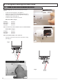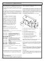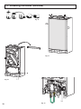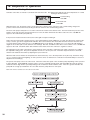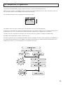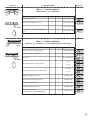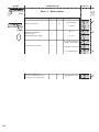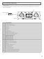
1
c
Minima HE
CONDENSING WALL HUNG COMBINATION BOILER
Heating and Instantaneous Domestic Hot Water - Fanned Flue system
Installation, Servicing and Operating Instructions
Manufacturers N°
Model Type
Gas Council N°
3650007.31
Minima HE 24 Nat
47 - 980 - 33
3650008.31
Minima HE 30 Nat
47 - 980 - 34
3650009.31
Minima HE 35 Nat
47 - 980 - 35
Country of destination GB
IE
These instructions are suitable for the Minima HE boilers :
Do not forget the Log Book!
Chaffoteaux & Maury supports Benchmark, the heating industry code to ensure the correct installation, commissioning and
servicing of domestic central heating systems.
To The Householder
Make sure that your installer completes Section 24 of this manual (page 60) . This provides a record of the
commissioning of your boiler.
It contains important information about your particular installation that may be required by service engineers. It will also provide
contact details for the installer should you need guidance in the use of this appliance or if there are any problems.
As with your car, your boiler will work more reliably and efficiently if regularly serviced. We recommend an annual service
check. The service history of the appliance must be recorded in Section 25 of this manual (page 61).
In the unlikely event of any problems with your boiler or system you should first contact your installer. If your installer cannot
resolve the problem he should telephone our national service helpline.
A charge may be made if Chaffoteaux & Maury Service is called out to resolve a non-product related fault.
Your statutory rights are not affected.
To The Installer
As part of the commissioning of this appliance it is necessary to complete Section 24 of this manual (page 60) and give this
manual to the Householder. Please ensure that your customer is aware of the importance of keeping this manual safe as a
record of the installation (Section 24, page 60) and the appliance service history (Section 25, page 61).
Please ensure that your customer is aware of the correct operation of the system, boiler and controls.
MTS recommend the use of protective clothing, when installing and working on the appliance i.e. gloves.
CUSTOMER CARE
Chaffoteaux & Maury, as a leading manufacturer of domestic and commercial water heating appliances is committed to
providing high quality products and a high quality after sales service.
Advice on installation or servicing can also be obtained by contacting the Chaffoteaux Technical and Customer Service
Departments at High Wycombe.
TECHNICAL DEPARTMENT
CUSTOMER SERVICE DEPARTMENT
Tel:
0870 241 8180
Tel:
0870 600 9888
Fax:
01494 459775
Fax:
01494 459775
GUARANTEE
The manufacturer`s guarantee is for 24 months from the date of purchase. The guarantee is voidable if the appliance is not
installed in accordance with the recommendations made herein or in a manner not approved by the manufacturer and if the
appliance is not serviced in accordance with manufacturers instructions and the Service Interval Record (Section 25, page 60)
is not completed after the first year. To assist us in providing you with an efficient after sales service, please return the guarantee registration card enclosed with the boiler without delay.
CAUTION
In the United Kingdom, installation, start-up, adjustments and maintenance, must be performed by a competent person only, in
accordance with the current Gas Safety (Installation & Use) Regulations and the instructions provided.
In the Republic of Ireland, the installation and initial start up of the appliance must be carried out by a Competent Person in
accordance with the current edition of I.S.813 “Domestic Gas Installations”, the current Buidling Regulations, reference should
also be made to the current ETCI rules for electrical installation.
All CORGI registered installers carry a CORGI ID card, and have a registration number. Both should be recorded in
your boiler Log Book. You can check your installer is CORGI registered by calling CORGI direct on:- (01256) 372300.
Improper installation may cause damage or injury to individuals, animals and personal property for which the manufacturer will
not be held liable. To ensure efficient and safe operation it is recommended that the boiler is serviced annually by a competent
person.
If it is known that a fault exists on the appliance, it must not be used until the fault has been corrected by a competent person.
This instruction booklet is especially designed for appliances installed in the UK and the Republic of Ireland
2
Contents
CUSTOMER CARE
Page
Guarantee ............................................................................................................................................................2
Statutory Requirements .......................................................................................................................................2
Contents ...............................................................................................................................................................3
INTRODUCTION ..................................................................................................................................................4
USER INSTRUCTIONS ........................................................................................................................................5
1 CONTROL PANEL...........................................................................................................................................5
2 HOW TO USE ..................................................................................................................................................6
3 MAINTENANCE ...............................................................................................................................................7
4 GUARANTEE...................................................................................................................................................7
5 PRACTICAL INFORMATION...........................................................................................................................7
6 FITTING AND SETTING THE TIME CLOCK...................................................................................................8
6.1
FITTING THE MECHANICAL AND DIGITAL CLOCKS ..........................................................................8
6.2
SETTING THE MECHANICAL CLOCK ...................................................................................................9
6.1
SETTING THE DIGITAL CLOCK...........................................................................................................10
INSTALLERS’ INSTRUCTIONS.........................................................................................................................12
7 DESCRIPTION...............................................................................................................................................12
8 DIMENSIONS ................................................................................................................................................13
9 HYDRAULIC DATA .......................................................................................................................................13
10 INSTALLATION REQUIREMENTS................................................................................................................14
11 INSTALLING THE BOILER............................................................................................................................17
12 CONNECTING THE FLUE.............................................................................................................................19
12.1
FITTING THE COAXIAL FLUE (Ø 60 / 100 HORIZONTAL) ................................................................ 20
12.2
FITTING THE 5” FLUE (Ø 80 / 125 HORIZONTAL/VERTICAL) .......................................................... 20
12.3
FITTING THE VERTICAL FLUE (Ø 60 / 100)....................................................................................... 22
12.4
FITTING THE TWIN FLUE (Ø 80 / 80) ................................................................................................ 23
13 ELECTRICAL CONNECTIONS .................................................................................................................... 26
14 COMMISSIONING AND TESTING ............................................................................................................... 28
14.1
INITIAL PREPARATION ....................................................................................................................... 28
14.2
INITIAL START-UP............................................................................................................................... 28
14.3
ADJUSTING THE CO2 ......................................................................................................................... 29
14.4
GAS CONVERSION ............................................................................................................................. 29
14.5
ADJUSTING THE MAXIMUM HEATING POWER ............................................................................... 29
14.6
FITTING THE EXTERNAL SENSOR.................................................................................................... 29
14.7
EXTERNAL SENSOR SET-UP............................................................................................................. 29
14.8
ADJUSTING THE PARALLEL SHIFT................................................................................................... 30
14.9
COMPLETION ...................................................................................................................................... 30
14.10 OPERATIONAL CHECKS .................................................................................................................... 30
14.11 INSTRUCTING THE END USER.......................................................................................................... 30
15 FITTING THE CASING ................................................................................................................................. 31
16 SEQUENCE OF OPERATION...................................................................................................................... 32
16.1
CENTRAL HEATING MODE ................................................................................................................ 32
16.2
DOMESTIC HOT WATER MODE......................................................................................................... 33
17 ADJUSTMENTS AND SETTINGS ................................................................................................................ 34
3
SERVICING INSTRUCTIONS
18 REPLACEMENT OF PARTS ........................................................................................................................ 41
18.1
To Gain General Access....................................................................................................................... 41
18.1.1 Removing the front panel...................................................................................................................... 41
18.1.2 Lowering the control panel.................................................................................................................... 41
18.2
Access to the Combustion Chamber .................................................................................................... 42
18.2.1 Removing the combustion chamber front panel ................................................................................... 42
18.2.2 Removing the burner ............................................................................................................................ 43
18.2.3 Removing the detection electrode ........................................................................................................ 43
18.2.4 Removing the ignition electrode............................................................................................................ 43
18.2.5 Removing the fan.................................................................................................................................. 44
18.2.6 Removing the gas valve........................................................................................................................ 44
18.2.7 Removing the heat exchanger .............................................................................................................. 45
18.2.8 Removing the spark generator.............................................................................................................. 45
18.3
ACCESS TO THE WATER CIRCUIT ................................................................................................... 46
18.3.1 Drain down............................................................................................................................................ 46
18.3.2 Removing the 3 way valve.................................................................................................................... 46
18.3.3 Removing the float of the flow switch ................................................................................................... 46
18.3.4 Removing the secondary heat exchanger ............................................................................................ 47
18.3.5 Removing the pump.............................................................................................................................. 47
18.3.6 Removing the pressure relief valve ..................................................................................................... 48
18.3.7 Removing the domestic expansion vessel............................................................................................ 48
18.3.8 Removing the overheat thermostat....................................................................................................... 48
18.3.9 Removing the temperature sensors (NTC’s) ........................................................................................ 48
18.3.10 Removing the pressure gauge.............................................................................................................. 49
18.3.11 Removing the DHW flow switch............................................................................................................ 49
18.4
ACCESS TO THE CONTROL SYSTEM .............................................................................................. 49
18.4.1 Removing the PCB’s............................................................................................................................. 49
18.4.2 Removing the fuses .............................................................................................................................. 50
18.5
CONNECTING THE EXTERNAL SENSOR ......................................................................................... 50
19 INCORRECT FUNCTION ............................................................................................................................. 51
20 MAINTENANCE INSTRUCTIONS ................................................................................................................ 52
20.1
GENERAL REMARKS.......................................................................................................................... 52
20.2
CLEANING THE PRIMARY EXCHANGER .......................................................................................... 52
20.3
OPERATIONAL TEST .......................................................................................................................... 53
21 SHORT SPARES LIST ................................................................................................................................. 54
22 NOTES.......................................................................................................................................................... 55
23 TECHNICAL DATA ....................................................................................................................................... 56
24 BENCHMARK COMMISSIONING CHECKLIST ........................................................................................... 59
25 SERVICE INTERVAL RECORD ................................................................................................................... 60
INTRODUCTION
The MINIMA HE is a fully automatic, wall mounted, low water content condensing combination boiler. It is a room
sealed, fan assisted, balanced flued appliance providing central heating and mains pressure domestic hot water
on demand. It has electronic ignition and is suitable for all modern electrical control systems. The boiler is
designed for sealed systems only and a circulating pump, expansion vessel together with a pressure gauge and
safety valve are included within the boiler.
4
USER INSTRUCTIONS
1. Control panel
29
16
26
27
25
30
28
Fig. 1
31
Control panel (Fig. 1)
34
39 : Gas service tap
40 : Water service tap
and temperature setting
30.- Central Heating control knob
31.- Menu key
32.- Reducing key
33.- Increasing key
34.- Setting key
33
Connecting bracket
Taps shown in Open position (Fig. 2)
25.- Display
26.- On/off push button and power on indicator light
27.- Yellow indicator - Comfort button
28.- Reset push button and red indicator lock-out light
29.- DHW control knob
32
41 : Central heating flow isolating valve
and temperature setting
42 : Central heating return isolating valve
43 & 44: Filling taps
45 : Filling loop
41
42
43
Fig. 2
44
45
39
40
5
2. How to use
Switching on and filling instructions
1. Check the pressure in the central heating system is above 0.7 bar and below 1.5 bar with the pressure gauge 16 (fig.1),
should it be neccessary to re-pressurise the system,ensure the filling loop 45 (fig. 2) is attached, open the filling taps 43 &
44, the pressure gauge will now start to rise, once the pressure reads 1.0 bar, close the filling taps and disconnect the filling
loop.
2. Check that the gas service tap is opened at the gas meter and the main power is on. Green indicator 26
Power ON
3. Open the gas tap 39 (fig.2).
4. The boiler is now ready to use.
+
+
NOTE:
If the boiler is left off for a long time, some air in the gas pipe can hinder the first lighting
attempts. (please refer to Section 19 Incorrect Function, page 47)
OPEN
CLOSED
Time setting
You can set the time by using the keys underneath the display.
By pressing the setting key for more than 5 seconds the hours willl begin to flash. You can now set the correct hour by using the
+ and - keys. By pressing the setting key will make the minutes flash. You can set the minutes by using the + or - keys.
Pressing the setting key once more will store the set time.
NOTE: THIS IS NOT A TIMER FOR CH CONTROL
DHW mode
Turn the control knob 29 between min and max. During the adjustment,
flashes.
The flashing goes on for a while after the adjustment, then the display indicates
the time.
When DHW is drawn, the
display indicates the following:
comfort
Comfort mode
To activate the comfort mode it is necessary to press the comfort button, this
will be indicated by a yellow light. The comfort mode has priority over any other
heating request.
There are two settings for the comfort mode (they can be adjusted in the
parameters menu, see Section 17 Adjustments and Settings):
1. As soon as DHW is drawn, the secondary heat exchanger is kept warm for
30 mins.
2. As soon as DHW is drawn, the secondary heat exchanger is kept warm
permanently.
When the boiler is operating in ‘comfort
mode’ the display indicates the following:
Heating mode
Turn the control knob 30 between min and max. During the adjustment
flashes.
The flashing goes on for a while after the adjustment, the display will then
indicate:
- the central heating flow temperature if the room thermostat is calling for heat.
- the time if the room thermostat is OFF.
Room thermostat request
symbol
BURNER ON and output level
The flame digits will increase or decrease depending on the output.
Flame digit
Burner ON
6
Stand-by mode
Turn the control knobs 29 and 30 to the OFF position to deactivate the DHW
and Heating. Leave the ON/OFF button On with the green light on.
During the stand-by mode the display indicates the time, anti-seizing and antifreezing will be active.
Switch OFF
Press the button ON/OFF.
During this mode the boiler will not operate, but is still connected to the mains.
Anti-freezing mode
Turn the control knobs 29 and 30 to OFF to switch off the heating and hot water
functions. Leave the On/Off button on with the green light on.
When the anti-freeze comes on, the corresponding code is displayed with the
snowflake pictogram
.
The two possible codes are 05 (anti-freeze - pump only) or 06 (anti-freeze burner).
05: When this mode is active, the circulating pump operates for one
minute and the diverter valve switches every 23 hours.
Caution: in this mode, the room thermostat anti-freeze function is
inoperative.
Boiler anti-freeze function:
the pump starts at 8°C
the burner starts at 3°C
3. Maintenance
As with your car, your boiler will work more reliably and efficiently if regularly serviced. We recommend an annual service
check. The service history of the appliance will be marked in the Log Book.
4. Guarantee
The manufacturer`s guarantee is for 24 months from the date of purchase. The guarantee is voidable if the appliance is not
installed in accordance with the recommendations made herein or in a manner not approved by the manufacturer and if the
appliance is not serviced in accordance with manufacturers instructions and the Service Interval Record (Section 25, page 60)
is not completed after the first year. To assist us in providing you with an efficient after sales service, please return the guarantee registration card enclosed with the boiler without delay.
5. Practical information
Cleaning the casing and control panel
Should it be necessary to clean the casing and control panel. do so only with a soft damp cloth, do not use any spray polishes
or cleaners.
Precaution to avoid freezing
We recommend you contact your installer or local service centre for further advice on the actions to be taken to avoid the
system freezing.
• DHW system
Turn off the main cold water supply and drain the boiler :
- Open a hot water tap
- Unscrew the cold water inlet tail
• CH system
Chose one of the following solutions :
- 1) Drain completely the Central Heating system
- 2) Protect the Central Heating system with anti freeze chemical products and verify the concentration periodically
- 3) Leave the Heating mode switched on and set the room thermostat to anti-freeze mode (between 5 and 10°C)
- 4) Leave your boiler in stand by mode, the anti-freeze device will switch on the pump and the burner if necessary.
7
6. Fitting and setting the time clock
6.1
Fitting the mechanical and digital time clocks
To fit the integral time clock it is necessary to proceed as
follows;
-
Isolate the electical supply to the appliance;
Remove the front panel as described in Section 18.1.1;
Remove the plastic cover on the right hand side (Fig. 3)
and pull out the 4 wires (Fig. 4);
Connect the time clock wires as follows;
MECHANICAL MODEL (Fig. 5)
Red Wire
Black Wire
Black Wire
Grey Wire
-
Contact 1
Contact 2
Contact 3
Contact 5
Fig. 3
NOTE: THE TWO BLACK WIRES ON CONTACTS 2 & 3 CAN BE REVERSED
DIGITAL MODEL (Fig. 6)
Red Wire
Black Wire
Grey Wire
-
Contact 1
Contact 2
Contact 3
NOTE: SECOND BLACK WIRE IS NOT CONNECTED.
-
Push the clock back into the panel and refit the casing
panel (Fig. 7).
Fig. 4
Fig. 5
5 4 3
G
2
B
1
R
Fig. 6
Fig. 7
8
6. Fitting and setting the time clock (continued)
6.2
Setting the mechanical clock
12
9
3
6
Fig. 8
A
3
2
4
1
24
23
22
12
5
21
C
6
7
19
9
20
I
8
18
9
17
B
15
14
13
10
16
6
12
11
Fig. 9
1. General layout
The mechanical clock covers a 24 hour period. Each tappet represents 15 minutes A (Fig. 9). An override switch is located on
the clock B (Fig 9).
2. To set the time
To set the time of day, grasp the outer edge of the dial and turn slowly clockwise until the correct time is lined up with the arrow
C (Fig. 4).
3. To Set the "On" and "Off" times
The clock uses a 24hours system. e.g. 8 = 8.00 am and
18 = 6.00 pm "ON" periods are set by sliding all tappets between the "ON" time and the "OFF" time to the outer edge of the
dial.The tappets remaining at the centre of the dial are the "OFF" periods.
4. For operation
symbol to control the central heating by the clock. Put the switch B to «I» to select
Put the selector switch B to the
permanent operation or to «0» to turn the central heating off permanently.
9
6. Fitting and setting the time clock (continued)
6.3
Setting the Digital Clock
Manual switch
Summer and
winter time
setting
Reset
Enter
the hours
h
Prog
.
Enter
switching
times
Weekdays
flash
m
Imput
time
Enter
minutes
Day
Enter
weekday/s
Operating the time switch
The steps marked with the symbol “
” are necessary to carry out a switching program.
Preparing for Operation
Activate the “Res” switch (=RESET) to reset the time switch to its default setting (activate using a pencil or similar pointed
instrument). Do this:
- every time you wish to “reset” the time switch
- to erase all switching times and the current time of day.
After approximately two seconds the following display appears:
Enter current time and weekday
- Keep the “ ” key pressed down
During the summer time period press the +/- 1h key once.
Enter the hour using the “h” key
Enter the minutes using the “m” key
Enter the day using the “Day” key
1 = “Monday”..............7 = Sunday
- Release the “ ” key.
10
6. Fitting and setting the time clock (continued)
Entering the switching times
You have 20 memory Iocations available. Each switching time takes up one memory location.
Keep pressing the “Prog” key until a free memory location is shown in the display “– –:– –”.
” key:
Programme ON or OFF with the “
“ ”= OFF; “ ”= ON
Enter the hour using “h”
Enter the minutes using “m”
If a switching command is to be carried out every day (1 2 3 4 5 6 7) then store using the “ ” key, otherwise select the
day(s) it is to be carried out by using the “Day” key.
When the day seIection is left bIank, the programmed switching instruction operates at the
same time every day
1 2 3 4 5 6 = Monday – Saturday
= Monday – Friday
12345
=Saturday – Sunday
67
Selection of single days: 1 = Mon. .............. 2 =Tues.
Save the switching time with the “ ” key.
The time switch enters the automatic operating mode and displays the current time of day.
Begin any further entry of a switching time with the “Prog” switch. If your entry is incomplete, the segments not yet selected
will blink in the display. After programming is completed, and you return the time clock to the current time display with the “
” key, the time clock will not activate any switching instruction required for the current time. You may need to manually select
the desired switching state with the “
” key. Thereafter, as the unit encounters further switching instructions in the memory
in real time, it will correctly activate all subsequent switching instructions.
Manual Override Switch “
”
With the “
” you can change the current setting at any time. The switching program already entered is not altered.
Reading the programmed switching times
Pressing the “Prog” key displays the programmed switching times until the first free memory location appears in the display “– – :
– –”.
If you now press the “Prog” key once again, the number of free memory Iocations will be displayed, e.g. “18”. If all memory
locations are occupied, the display “00” appears.
Changing the programmed switching times
Press the “Prog” key repeatedly until the switching time you want to change is displayed. You can now enter the new data. See
point “Entering the switching times”.
Notes on storing switching times:
If you end your entry of the switching times by pressing the “Prog” key, then the switching time you have entered will be stored
and the next memory location displayed.
In addition, a complete switching command is stored automatically after around 90 seconds provided no other key is pressed.
The time switch then enters the automatic operating mode and displays the current time again.
Deleting individual switching times
Press the “Prog” key repeatedly until the switching time you wish to delete is shown in the display. Then set to “– –” using the “h”
or “m” key and keep the “ ” key pressed down for around 3 seconds. The switching time is now erased and the current time is
displayed.
AM / PM time display
If you press the “+/-1h” and “h” keys at the same time, the time display switches into the AM/PM mode.
11
INSTALLER INSTRUCTIONS
7. Description
1.- Steel chassis complete with expansion vessel
2.- Sealed chamber
3.- Burner and heat exchanger assembly
4.- Air / gas connection
5.- 24 V modulating fan
6.- Gas valve
7.- Ignition electrode
8.- Ionisation probe
9.- Ignitor
10.- Combustion products manifold
11.- Siphon
12.- Silencer
13.- Electrical box
14.- Pump
15.- Secondary heat exchanger
16.- Pressure gauge
17.- Three way valve
18.- Automatic air vent
19 - Domestic hot water flowswitch
20.- Main exchanger inlet thermistor
21.- Main exchanger outlet thermistor
22.- Overheat sensor
23.- Central heating pressure relief valve
1
10
2
9
7
3
8
20
4
22
21
12
5
6
42
17
15
18
13
14
23
19
16
11
Fig. 10
Fig. 11
29
26
27
25
30
28
25.- Display
26.- On/off push button and power on
indicator light
27.- Yellow indicator - Comfort button
28.- Reset push button and red indicator
locking light
29.- DHW control knob
setting
and temperature
30.- Central Heating control knob
temperature setting
31.- Menu key
32.- Reducing key
33.- Increasing key
34.- Setting key
Fig. 12
12
31
32
33
34
and
8. Dimensions
All dimensions in mm
289
21
Safety valve C/H and condensate
J
Heating flow
K
D.H.W. outlet
L
Gas supply
M
Cold water inlet
N
Heating return
With packaging :
24 kW : 37 kg
30 kW : 40 kg
35 kW : 41 kg
691,5
720
141
I
172,5
I
121,5
4,7
minimum
space
required
450
450 mini
pour
entretien
J KLM N
I
32
440
390
296
296 (24
kW)
360 (30/35 kW)
54 54 54 54
Fig. 13
J K L M N
9. Hydraulic data
The boiler is fitted with an automatic by-pass as standard.
Pump Head Graph (15/50)
The graph (Fig. 9) shows the developmentof the pressure
available in relation to flow (on exit from the boiler ∆T 20°C).
0.45
0.4
To ensure correct operation, the minimum flow of the
appliance must be 300 l/h. (Thermostatic taps closed).
Pressure (bar)
0.35
0.3
Capacity of the installation.
0.25
The water heater is fitted with a pressurised expansion
vessel.
0.2
0.15
Maximum volume of expansion vessel: 6 litres.(24 kW)
0.1
7 litres.(30 / 35 kW)
0.05
Pressure: 1 bar.
0
0
200
400
600
800
1000
1200
1400
The volume of the expansion vessel in a pressurised
appliance varies according to:
flow rate (l/hr)
- the average operating temperature in °C
Pump Head Graph (15/60)
- the static height, which is the difference in metres between
the highest point of the appliance and the expansion vessel
axis).
The minimum cold filling pressure of the appliance is 1 bar
(recommended pressure between 1.2 and 1.7 bar).
Pressure (bar)
The pressure of the expansion vessel should always be
greater than the static height (in metres) divided by 10.
Fig. 14
Pression à froid
pour le circuit
chauffage
(en bar) when cold (in bar)
Central
heating
initial
pressure
Pf
2,0
1,9
1,8
40°C
1,7
1,6
flow rate (l/hr)
50°C
1,5
1,4
60°C
1,3
70°C
1,2
80°C
1,1
1,0
20
40
60
80
100
120
140
160
180
200
Capacité
maximale de l'installation (en litres)
System capacity
chart
220
240
260
280
C litre
13
10. Installation requirements
Reference Standards
In the United Kingdom, the installation and initial start up of
the boiler must be by a CORGI Registered installer in
accordance with the installation standards curently in effect,
as well as with any and all local health and safety standards
i.e. CORGI.
In the Republic of Ireland the installation and initial start up of
the appliance must be carried out by a Competent Person in
accordance with the current edition of I.S.813 “Domestic Gas
Installations” and the current Building Regulations, reference
should also be made the the current ETCI rules for electrical
installation.
must not be installed in a place likely to cause nuisance. It
must not be allowed to discharge into another room or space
such as an outhouse or closed lean-to.
Condensing boilers have a tendency to form a plume of water
vapour from the flue terminal due to the low temperature of the
flue gasses. The terminal should therefore be located with due
regard for the damage or discolouration that might occur to
buildings in the vicinity and consideration must also be given to
adjacent boundaries, openable windows should also be taken
into consideration when siting the flue.
The minimum acceptable clearances are shown below:
Fig. 15
The installation of this appliance must be
in accordance with the relevant
requirements of the Local Building
Regulations, the current I.E.E. Wiring
Regulations, the by-laws of the local water
authority, in Scotland, in accordance with
the Building Standards (Scotland)
Regulation and Health and Safety
document No. 635, “Elelectricity at Work
Regulations 1989” and in the Republic of
Ireland with the current edition of I.S. 813
and the Local Building Regulations (IE).
C.O.S.H.H.
Materials used in the manufacture of this
appliance are non-hazardous and no
special precautions are required when servicing.
Codes of Practice
Installation should also comply with the following British
Standards Codes of Practice:
BS 7593:1992
Treatment of water in domestic hot
water central heating systems
BS 5546:1990
Installation of hot water supplies for
domestic purposes
BS 5440-1:2000 Flues
BS 5440-2:2000 Air Supply
Forced ciculation hot water systems
BS 5449:1990
BS 6798:2000
Installation of gas fired hot water
boilers of rated input not exceeding
70kW
BS 6891:1989
Installation of low pressure gas pipe up
to 28mm
BS 7671:2001
IEE Wiring Regulations
Specification for expansion vessels
BS 4814:1990
BS 5482:1994
Installation of L.P.G.
and in the Republic of Ireland in accordance with the
following codes of practice
I.S. 813
Domestic Gas Installations
Avoid installing the boiler where the air inlet can be polluted
by chemical products such as chlorine (swimming pool area),
or ammonia (hair-dresser), or alkalin products (launderette)
Flue
Detailed information on flue assembly can be found in Section
12 “Connecting the flue”.
The boiler must be installed so that the flue terminal is
exposed to the free passage of external air at all times and
14
E
E
ABCDEF GHI J KL -
Directly below an open window or other opening
Below gutters, solid pipes or drain pipes
Below eaves
From vertical drain pipes and soil pipes
From internal or external corners
Above ground on a public walkway or patio
From a surface facing a terminal
From a terminal facing a terminal
Vertically from a terminal in the same wall
Horizontally from a terminal in the same wall
Horizontally from an opening window
Fixed by vertical flue terminal
NOTE: THE
300
75
200
75
300
2100
2500
2500
1500
300
300
FLUE MUST NOT BE INSTALLED UNDER A CAR PORT
ROOF OR IN A PLACE LIKELY TO CAUSE A NUISANCE.
It may be necessary to protect the terminal with a guard, if this is
the case it will be necessary to purchase a stainless steel terminal
guard. Reference should be made to the Building Regulations for
guidance.
Ventilation
The room in which the boiler is installed does not require specific
ventilation. If it is installed in a cupboard or compartment
permanent ventilation is not required for cooling purposes.
Gas Supply
The gas installation and soundness testing must be in
accordance with the requirements of BS 6891. Ensure that
the pipe size is adequate for demand including other gas
appliances on the same supply.
10. Installation requirements (continued)
Electrical Supply
The appliance requires an earthed 230V - 50 Hz supply and
must be in accordance with current I.E.E. It must also be
possible to be able to completely isolate the appliance
electrically. Connection should be via a 3 amp fused doublepole isolating switch with contact separation of at least 3 mm
on both poles. Alternatively, a fused 3 Amp. 3 pin plug and
unswitched socket may be used, provided it is not used in a
room containing a bath or shower. It should only supply the
appliance.
The boiler is suitable for sealed systems only. The maximum
working pressure for the appliance is 6 bar. All fittings and
pipework connected to the appliance should be of the same
standard. If there is a possibility of the incoming mains
pressure exceeding 6 bar, particularly at night, then a
suitable pressure limiting valve must be fitted.
The boiler is designed to provide hot water on demand to
multiple outlets within the property. If there is a requirement
for greater demands, for example if the property has several
bathrooms and cloakrooms, a vented or unvented hot water
storage system may be used.
Showers
Any shower valves used with the appliance should be of a
thermostatic or pressure balanced type. Refer to the shower
manufacturer for performance guidance and suitability.
Flushing and Water Treatment
The performance of the appliance could be impaired by
system debris or the effects of corrosion. When the
installation and filling are completed, flush the system while
cold, refill, turn on the Central Heating System (Section 2
page 6) and run it until the boiler reaches its operating
temperature. The system must then be immediately flushed
through. The flushing procedure must be in line with BS
7593:1992 code of practice for treatment of water in
domestic hot water central heating systems.
During this operation the use of a central heating flushing
detergent is compulsory, whose function is to disolve any
foreign matter that may be in the boiler and system following
the flushing procedure.
Substances different from these could create serious
problems to the pump or other components.
The use of an inhibitor is also compulsory to prevent
corrosion (sludge) damaging the boiler and system.
Failure to carry out this procedure will invalidate the
appliance warranty.
For more information on the use of corrosion inhibitors,
flushing and descaling agents, advice can be sought from the
manufacturers of water treatment products such as:
Betz Dearborn Ltd
Foundry Lane
Widnes
Cheshire
WA8 8UD
Tel: 0151 424 5351
System Controls
The boiler is electrically controlled and is suitable for most
modern electronic time and temperature controls. The
addition of such external controls can be beneficial to the
efficient operation of the system. The boiler connections for
external controls are 24V and so only controls of 24V or that
have voltage free contacts should be used. (Section 13
Electrical Connections - page 27).
Location
The boiler can be installed on any suitable internal wall.
Provision must be made to allow the correct routing of the flue
and siting of the terminal to allow the safe and efficient
removal of the flue products. A compartment or cupboard may
be used provided that it has been purpose-built or modified for
the purpose. It is not necessary to provide permanent
ventilation for cooling purposes. Detailed recommendations
are given in BS 5440 pt 2. If it is proposed that it is installed in
a timber framed building then reference should be made to
British Gas Document DM2, or advice sought from CORGI.
Where a room sealed appliance is installed in a room
containing a bath or shower, the appliance and any
electrical switch or appliance control, utilising mains
electricity should be situated specifically in accordance
with current IEE Wiring Regulations.
For unusual locations, special procedures may be necessary.
BS 6798:2000 gives detailed guidance on this aspect.
Condensate Discharge
The condensate discharge hose from the boiler must have a
continuous fall of 2.5o and must be inserted by at least 50mm
into a suitable acid resistant pipe - e.g. plastic waste or
overflow pipe. The condensate discharge pipe must have a
minimum diameter of 22mm, must have a continuous fall and
preferably be installed and terminated to prevent freezing.
The discharge pipe must be terminated in a suitable position:
Connecting into an internal soil stack (at least 450mm
above the invert of the stack). A trap giving a water seal
of at least 75mm must be incorporated into the pipe run,
there also must be an air break upstream of the trap.
ii) Connecting into the waste system of the building such as
a washing machine or sink trap. The connection must be
upstream of the washing machine/sink. If the connection
is down stream of the waste trap then an additional trap
giving a minimum water seal of 75mm and an air break
must be incorporated in the pipe run, as above.
iii) Terminating into a gully, below the grid level but above
the water level.
iv) Into a soakaway.
i)
NOTE: If any condensate pipework is to be installed
externally then it should be kept to a minimum and be
insulated with a waterproof insulation and have a continuous
fall. The total length of external pipe used should not exceed
3 metres.
Some examples of the type of condensate terminations can
be found on page 13.
Fernox Manufacturing
Britannica Works
Clavering
Essex
CB11 4QZ
Tel: 01799 550811
15
10. Installation requirements (continued)
16
1. Internal termination of condensate drainage pipe to
internal stack
2. External termination of condensate drainage pipe via
internal discharge branch (e.g. sink waste) and condensate
siphon
3. External termination of condensate drainage pipe via
internal discharge branch (e.g. sink waste - proprietary fitting).
4. External termination of condensate drainage pipe via
condensate siphon
11. Installing the boiler
Please check that you are familiar with the installation requirements before commencing work (Section 10).
The installation accessories described in the following list are included in the boiler packaging:
- Hanging bracket
- A paper template (showing the dimensions of the boiler with 5 mm side clearances)
- Connection tails and valves
- Screws and washers
- Connection washers
- Installation, Servicing and Operating Instructions
Method of positioning the boiler on the wall.
The paper template can be used to ensure the correct positioning of kitchen cabinets etc. It also details the commissioning
instructions.
The paper template has to be fixed to the wall and used to locate the position of the hanging bracket and the centre for the flue
hole.
Drill and plug the wall and secure the hanging bracket using the screws provided. Remove the boiler from its packaging as
shown in Fig. 16 and unscrew the two clamp locking bolts A and remove the casing (Fig. 17).
Place the boiler on the wall on the hanging bracket (Fig. 18).
NOTE: THE APPLIANCE MUST NOT BE FITTED ON A COMBUSTIBLE WALL SURFACE.
Connecting the boiler to the system
- Remove the boiler casing as described in Section 18.
- Push in the tabs “P” (Fig. 18) on either side of the boiler and pivot the electrical box forward to gain access to the valve
connections
- Remove the caps and connect the boiler to the taps using washers provided in the plastic bag.
4 x fibre washers for the C/H flow and return, hot water outlet and cold water inlet connections
1 x rubber washer for gas connection
Safety valve discharge
The pressure relief valve tube is made of copper. It should terminate below the boiler safely outside the premises. Care should
be taken that it does not terminate over an entrance or window or where a discharge of heated water could endanger
occupants or passers by.
Fill the Central Heating and DHW system and bleed air from system as described in Section 14.
The system should be carefully checked for leaks, as frequent refilling could cause premature system corrosion or
unnecessary scaling of the heat exchanger. The pipe from the siphon (11 Fig. 11) should be connected to a drain as described
in the relevant Brittish regulations.
Pay special attention to not bend the condensate silicone drain pipe such as the flow will be interrupted. Please use exclusively
drain pipe material compatible with condensate products. (refer to BS 6798 : 2000)
The condensate flow can reach 2 litres / hour; because of the acidity of the condensate products (Ph close to 2), take care
before operation.
Fitting the Horizontal Flue
Attention ! Before starting the boiler, the siphon (11 Fig. 11) must be filled with water. Before fitting the flue l onto the
boiler, pour 1/4 litre of water in the exhaust pipe as shown in Fig. 20.
Instructions on fitting the flue can be found in Section 12.
IMPORTANT!!
Use only the specific condensation flue kit supplied by C&M.
17
11. Installing the boiler (continued)
A
A
Fig. 16
1
2
Fig. 17
P
P
Fig. 18
18
Fig. 19
12. Connecting the Flue
The boiler should only be installed with a flue system supplied by MTS (GB) Limited.
These kits are supplied separately to the appliance in order to respond to different installation solutions. For more information
with regard to the inlet/outlet accessories consult the accessory catalogue. The boiler is supplied ready for connection to a
concentric flue system.
NOTE: SEE PAGE 24 FOR MAXIMUM AND MINIMUM FLUE RUNS (TABLES A, B AND C)
IMPORTANT!!
BEFORE CONNECTING THE FLUE, ENSURE THAT
1/4
LITRE OF
WATER HAS BEEN POURED INTO THE EXHAUST CONNECTION
(FIG. 20).
TO FILL THE CONDENSATE TRAP
SHOULD THE
TRAP BE EMPTY THERE IS A TEMPORARY RISK OF FLUE
GASSES ESCAPING INTO THE ROOM.
Fig. 20
Warning
The exhaust gas ducts must not be in contact with or close to inflammable
material and must not pass through building structures or walls made of
inflammable material.
When replacing an old appliance, the flue system must be changed.
Important
Ensure that the flue is not blocked.
Ensure that the flue is supported and
assembled in accordance with these
instructions.
Ø 60/100 mm
5
Fig. 21
Level
118
Installation without extension
150 mm
Fig. 22
Level
Installation with extension
* slope
150 mm
* slope 5 mm per metre
12.1 Fitting the coaxial flue (Ø 60/100 Horizontal)
CONTENTS:
1X SILICONE O-RING (60mm)
1X ELBOW (90 )
2X WALL SEALS (INTERNAL & EXTERNAL)
1X FLUE PIPE INCLUDING TERMINAL (1 METRE - 60/100)
1X FLUE CLAMP
1X SCREWS
1x Seal
Once the boiler has been positioned on the wall, insert the elbow into the socket and rotate to the required position.
possible to rotate the elbow 360o on its vertical axis.
O
NOTE:
It is
Using the flue clamp, seals and screws supplied (Fig 23) secure the elbow to the boiler.
The 1 metre horizontal flue kit (3318073) supplied is suitable for an exact X dimension of 815mm.
Measure the distance from the face of the external wall to the face of the flue elbow (X - Fig 21), this figure must now be
subtracted from 815mm, you now have the total amount to be cut from the plain end of the flue.
Draw a circle around the outer flue and cut the flue to the required length taking care not to cut the inner flue, next cut the inner
flue ensuring that the length between the inner and outer flue is maintained. (Fig 23).
e.g.
X = 555mm
815-555 = 260mm (Length to be cut from the plain end of the flue).
Once cut to the required length, ensure that the flue is free from burrs and reassemble the flue. If fitting the flue from inside of the
building attach the grey outer wall seal to the flue terminal and push the flue through the hole, once the wall seal has passed
through the hole, pull the flue back until the seal is flush with the wall. Alternatively, the flue can be installed from outside of the
building, the grey outer seal being fitted last.
Clamp
Screws
Seal
Fig. 23
12.2 Fitting the 5” Flue (Ø 80 / 125 Horizontal/vertical)
Should the flue require extending, the flue connections are push fit, however, one flue bracket should be used to secure each
metre of flue.
NOTE: SEE PAGE 19 FOR MAXIMUM AND MINIMUM FLUE RUNS.
Once the boiler has been positioned on the wall, it is necessary to insert the Ø80/125 adaptor (FIG. 24) for both horizontal and
vertical flue runs into the boiler flue socket (not supplied with flue kit - Part No 3318095).
Push the adaptor onto the boilers flue connection, grease the seals then add extensions or elbows as required, secure the
adaptor, using the clamp and screws provided.
To fit extensions or elbows it is first necessary to ensure that the lip seal is fitted correctly into the inner flue, once verified, it is
simply necessary to push them together, no clamps are necessary to secure the flue components.
Before proceeding to fit the flue, ensure that the maximum flue length has not been exceeded (See the tables on Page 19) and
that all elbows and bends have been taken into consideration, the maximum flue length is 10 metres, for each additional 90o elbow
1 metre must be subtracted from the total flue length, and for each 45o 0.5 metres must be subtracted from the total flue length
(the height of the vertical adaptor and a 45o bend can be seen in Fig. 25 and a 90o bend in Fig. 26).
NOTE: DO NOT CUT THE VERTICAL FLUE KIT.
Fig. 24
Fig. 25
Fig. 26
12.3 Fitting the Coaxial Flue (Ø 60 / 100 Vertical)
NOTE: SEE PAGE 24 FOR MAXIMUM AND MINIMUM FLUE RUNS.
CONTENTS:
1X SILICONE O-RING (60mm)
1X CONICAL ADAPTOR (60/100mm)
1X VERTICAL FLUE KIT (80/125mm)
3X SCREWS
The vertical flue kit is supplied with a specially designed weather proof terminal fitted, it can be used either with a flat roof or a
pitched roof.
The Vertical flue kits useable lengths with the pitched roof flashings are indicated in Fig. 27.
Before proceeding to fit the flue, ensure that the maximum flue length has not been exceeded (See the tables on Page 19) and
that all elbows and bends have been taken into consideration, the maximum flue length is 4 metres, for each additional 90o elbow
1 metre must be subtracted from the total flue length, and for each 45o 0.5 metres must be subtracted from the total flue length
(the height of the vertical adaptor and a 45o bend can be seen in Fig. 28).
Mark the position of the flue hole in the ceiling and/or roof (see Fig. 27 for distance from wall to the centre of the flue).
Cut a 120mm diameter hole through the ceiling and/or roof and fit the flashing plate to the roof.
DO NOT cut the vertical flue kit.
To connect the vertical flue kit directly to the boiler, place the vertical starter kit (Part No. 3318079) (see Figs. 27 & 28) onto the
exhaust manifold and secure with the clamp, fit the vertical adaptor onto the vertical starter kit (note: there is no need to use a
clamp to secure this as it is a push fit connection), the vertical flue kit must then be inserted through the roof flashing, this will
ensure that the correct clearance above the roof is provided as the terminal is a fixed height.
Should extensions be required, they are available in 1 metre (Part No. 3318077), 500mm (Part No. 3318078) and 160mm
lengths, they must be connected directly to the vertical starter kit before connecting the adaptor to allow the vertical flue kit to be
fitted. In the event that extension pieces need to be shortened, they must only be cut at the male end and it must be ensured
that the inner and outer flue remain flush.
When utilising the vertical flue system, action must be taken to ensure that the flue is supported adequately to prevent the weight
being transferred to the appliance flue connection by using 1 flue bracket per extension.
When the flue passes through a ceiling or wooden floor, there must be an air gap of 25mm between any part of the flue system
and any combustible material. The use of a ceiling plate will facilitate this. Also when the flue passes from one room to another
a fire stop must be fitted to prevent the passage of smoke or fire, irrespective of the structural material through which the flue
passes.
Fig. 27
Fig. 28
12. Connecting the flue (continued)
12.4 Fitting the twin pipe (Ø80/80)
NOTE: SEE PAGE 24 FOR MAXIMUM AND MINIMUM FLUE RUNS (TABLE C)
Where it is not possible to terminate the flue within the distance permitted for coaxial flues, the twin flue pipe can be used by
fitting a special adaptor to the flue connector and using the aperture for the air intake located on top of the combustion
chamber.
Always ensure that the flue is adequately supported, avoiding low points. (MTS supply suitable clamps as Part No. 705778).
To utilise the air intake it is necessary to:
1) Take the air intake cover off
2) Assemble the flange on the header supplied with the boiler
3) Insert the restrictor if necessary, on the tube or the elbow
4) Insert the header on the tube or the elbow up until the lower stop
(you do not have to use the washer).
5) Insert the elbow/header in the boiler air intake hole and fasten it with screws
The twin flue pipes can be fitted with or without additional elbows and need no clamps, simply ensure that the red o-ring is
inserted in the female end of the flue pipe and push the extension piece fully into the previous section of flue pipe or elbow,
check that the o-ring is not dislodged when assembling the flue.
Twin pipe can also be converted back to Coaxial flue to enable vertical termination with a coaxial kit by using the pipe bridge
(Twin - Coaxial Adaptor - Part No. 705767). When running the twin flue pipe vertically.
It is not recommended that the pipe bridge for horizontal termination, however in the unlikely event that this proves to be a
necessity it is extremely important that the entire flue has a fall of 5mm in every metre back to the boiler, and where the 60mm
inner flue of the concentric terminal connects to the pipe bridge, this point must be adequately sealed with silicone sealant to
avoid condense leakage at this point.
When siting the twin flue pipe, the air intake and exhaust terminals must terminate on the same wall, the centres of the
terminals must be a minimum of 280 mm apart and the air intake must not be sited above the exhaust terminal (refer to Fig.
33). The air intake pipe can be run horizontally, however, the terminal and the final 1 metre of flue must be installed with a fall
away from the boiler to avoid rain ingress.
It is also strongly recommended that the air intake pipe run be constructed of insulated pipe to prevent condense forming on
the outside of the tube.
The maximum permissible flue length for twin flue is dependent on the type of run used.
For flue runs with the intake and exhaust pipes under the same atmospheric conditions (TYPE 4) the maximum length is 60
metres (24kW and 30kW), for runs with the terminals under different atmospheric conditions (TYPE 5) the exhaust terminal
must extend 0.5 metres above the ridge of the roof (this is not obligatory if the exhaust and air intake pipes are located on the
same side of the building). For TYPE 5 also, the maximum permissible combined length is 60 metres (24kW and 30kW).
The maximum length is reached by combining the total lengths of both the air intake and exhaust pipes. Therefore a maximum
length of 60o metres for example, will allow a flue run of 30 metres for the air intake and 30 metres for the exhaust pipes, also
for each 90 elbow 2.2 metres must be subtracted from the total length and for each 45o elbow 1.4 metres must be subtracted
from the total flue length.
Some of the acceptable flue configurations are detailed page 25.
For further information relating to flue runs not illustrated, please contact the Technical Department on 0870 241 8180.
Fig. 29
141
200
230 MIN *
132
123.5
Fig. 30
12. Connecting the flue (continued)
123.5
107
200
25
ø 100
Fig. 31
In the event that twin flue pipes are used, and the boiler
has a side clearance of less than 60mm from the wall, it
is necessary to cut a larger diameter hole for the flue
pipe, this should be ø100 mm, this will then allow for
easier assembly of the air intake elbow and the tube
outside the wall (see Fig. 32).
60 mm
Fig. 32
TABLE
A
TABLE
B
TABLE
C
Concentric outlet
60/100
Min length
Max. length
24 , 30 and 35 kW
(Type 1, Type 2, Type 3)
0.3 m
5m
Length
equivalency for
45o
elbow
0.5 m
90o
elbow
1m
Concentric outlet
80/125
Min length
Max. length
24 , 30 and 35 kW
(Type 1)
0.3 m
10 m
45o
elbow
0.5 m
24 , 30 and 35 kW
(Type 2, Type 3)
0.3 m
10 m
90o
elbow
1m
Twin flue outlet
24 , 30 and 35 kW
Min length
Max. length
Type 4
80/80
10 m
60 m
(30m air / 30m exhaust)
45o
elbow
1.4 m
Type 5
80/80
10 m
60 m
(30m air / 30m exhaust)
90o
elbow
2.2 m
For coaxial systems, the maximum development value, mentioned in the table above also takes into account an elbow.
For twin flue systems the maximum development value, mentioned in the table includes the exhaust gas/air intake terminal.
Type 5 outlets should respect the following instructions:
1- Use the same ø 80 mm flue pipes for the gas intakes and exhaust gas ducts.
2- If you need to insert elbows in the gas intake and exhaust gas ducts, you should consider for each one the equivalent length
to be included in the calculation of developed length.
3- The exhaust gas duct should jut above the roof by at least 0.5 m.
4- The intake and exhaust gas ducts in Type 5 must be installed on the same wall, or where the exhaust is vertical and the air
intake horizontal, the terminals must be on the same side of the building.
12. Connecting the flue (continued)
TYPE 1
TYPE 4
TYPE 3
TYPE 2
TYPE 5
NOTE: DRAWINGS ARE INDICATIVE OF FLUEING OPTIONS ONLY.
AIR INTAKE MUST NOT BE
FITTED ABOVE THE EXHAUST
AIR INTAKE
EXHAUST
AIR INTAKE
Fig. 33
13. Electrical connections
Making the Electrical Connections
Hinge down the electrical box to gain access to the
electrical connections. Push in the tabs P (Fig. 34)
on either side of the boiler and pivot the box forward.
Remove the PCB cover (see Section 18.4 - page
50). Connect the live neutral and earth wires to
the main cable.
P
If using a room thermostat or other external control, they can be connected in place of the link on
the terminal block (Diagram A- Fig.36).
Note: Use only controls designed for voltage free
switching or 24V supply. Do not connect to a 230V
supply, and do not run 230v cables alongside the
low voltage cables.
P
Fig. 34
All necessary settings for room thermostat operations are described in Section 17 ADJUSTMENTS
AND SETTINGS.
4
1
3
2
15
Fig. 35
LEGEND
1
2
3
4
5
6
7
26
14
NTC Connectors
Display Connectors
EEPROM Key
24V DC Supply
Fan Connector
Flame Detection Connector
Fuses 2A 230V (X2)
13
12
11
5
8
9
10
11
12
13
14
15
10
6
7
9
230V Connector
Auxillary 230V Connector
Actuators 230V Connector
Time Clock Connector (Internal)
Room Thermostat Connector
Remote Control Connector
Under Floor Heating Connector
Not Used
8
13. Electrical connections (continued)
-
If a remote time clock is to be fitted, using a volt-free switching time clock, remove the link wire and connect the
switching wires from the time clock following points above (see also Diagram B Fig. 36).
-
If using an external time clock and room thermostat, remove the link wire and connect in series as above (see also
Diagram C Fig. 36).
Live and Neutral connections to operate the clock motor must be taken from a suitable source.
Connector 11 (Fig. 36), is provided for connecting an optional integral time clock or programmer, for fitting instructions, please
refer to those provided with the clock or page 8 of this manual.
CONNECTOR 12 ON
PCB, SEE FIG. 35
CONNECTOR 12 ON
PCB, SEE FIG. 35
CONNECTOR 12 ON
PCB, SEE FIG. 35
Fig. 36
27
14. Commissioning and testing
14.1 Initial preparation
MTS (GB) Limited support the
initiative. In
Sections 24 and 25 (pages 59 and 60) of this manual the
Commissioning Checklist and Service Interval
Record can be found. It is important that this is completed in
the presence of your customer, they are shown how to use it,
and it is signed by them. Please instruct your customer that
they must have this manual with them whenever they contact
a service engineer or us.
Preliminary electrical system checks to ensure electrical
safety must be carried out by a competent person i.e.
polarity, earth continuity, resistance to earth and short circuit.
FILLING THE HEATING SYSTEM:
Remove the front casing panel and lower the control panel
as described in Section 18.1 (page 37).
Open the central heating flow and return cocks supplied with
the connection kit;
Unscrew the cap on the automatic air release valve one full
turn and leave open permanently;
Close all air release valves on the central heating system;
Gradually open the valves at the filling point (filling loop) until
water is heard to flow, do not open fully;
Open each air release tap starting with the lowest point and
close them only when clear water free of air is visible;
The use of an inhibitor is also compulsory to prevent
corrosion (sludge) damaging the boiler and system.
Failure to carry out this procedure will invalidate the
14.2 Initial start-up
Purge the air from the pump by unscrewing the pump
plug anti-clockwise, also manually rotate the pump shaft
in the direction indicated by the pump label to ensure
the pump is free.
appliance warranty.
Refit the pump plug;
Continue filling the system until at least 1.5 bar registers on
the pressure gauge;
Inspect the system for water soundness and remedy any
leaks discovered.
1. Make sure that:
- The screw on the automatic air valve has been loosened
when the system is full;
- If the water pressure in the system is below 1.5 bar, bring
it up to the appropriate level;
- Ensure that the gas cock is closed;
- Make sure that the electrical connection has been made
properly and that the earth wire is connected to an
efficient earthing system;
- Supply power to the boiler by pushing the on/off button 26
(Fig. 1) the green led indicator light will illuminate;
-Turn the central heating control knob 29 (Fig. 1) to
maximum and switch the time clock (if fitted) to constant
and turn up the room thermostat (where fitted);
- After 7 seconds, the boiler will signal a shutdown due to
ignition failure. Leave the boiler as it is until all the air
has been bled from the system;
- Loosen the cap on the head of the pump to eliminate any
air pockets;
- Repeat the procedure for bleeding the radiators of air;
- Open the hot water taps for a short period;
- Check the system pressure and , if it has dropped, open
the filling loop again to bring the pressure back up to 1.5
bar;
2. Make sure that all radiator valves are open;
3. Turn on the gas cock and check the seals on the
connections with any approved soap solution and eliminate
any leaks;
4. Press the reset button 28 (Fig. 1) the boiler will re-attempt
ignition. If the burner does not light the first time, wait 1
minute and repeat the procedure;
5. Check the minimum and maximum CO2 values and gas
rates;- Adjust if necessary using the values indicated in the
table in Fig. 31 (page 32)
FILLING OF THE DHW SYSTEM:
Close all hot water draw off taps;
Open the cold water inlet cock supplied with the connection
kit;
Slowly open each draw off tap and close them only when
clear water, free of bubbles, is visible.
GAS SUPPLY:
Inspect the entire installation including the gas meter and test
for soundness. The entire installation should be in
accordance with the relevant standards. In GB this is BS
6891 and in IE this is the current edition on I.S.813.
The connection on the the appliance is a 15mm copper tail
located at the rear of the gas service cock (39 Fig. 2 - page
5)
If the gas supply serves other appliances, ensure that an
adequate supply is available both to the boiler and the other
appliances when they are in use at the same time.
Pipe work must be of an adequate size. Pipes of less than
22mm should not be used.
Open the gas cock (supplied with the connection kit) to the
appliance and check the gas connection on the appliance for
leaks.
28
When installation and filling are completed, adequately purge
the gas installation of air, flush the sytem while cold, refill,
turn on the Central Heating system (Section 2 - page 6) and
run it until the boiler operating temperature has been
reached. The system must then be immediately flushed
through.
The flushing procedure must be in line with BS 7593:1992
code of practice for treatment of water in domestic hot water
central heating systems.
During this operation, we highly recommend the use of a
central heating flushing detergent (Fernox Superfloc or
equivalent), whose function is to disolve any foreign matter
that may be in the boiler and sytem following the flushing
procedure.
Substances different from these could create serious
problems to the pump or other components.
The checks to be run before initial start-up are as
follows:
14. Commissioning and testing (continued)
14.3 Adjusting the CO2
1. Remove the casing panel as described in Section 18
(page 42);
2. Connect a combustion analyser to the test point on top of
the boiler Q (Fig. 37);
3. Access the seetings menu by pressing the
and
keys together for 5 seconds;
4. Press the menu button
to access Menu 5 and press the
setting button once
to switch the combustion rate
control mode to maximum;
5. Adjust the screw on the gas valve (Fig. 38) to set the CO2
to 9.2% +/- 0.2% (NG) or 10% +/- 0.2% (LPG);
once to set the combustion
6. Press the setting button
control rate mode to minimum, and, if necessary, adjust the
screw on the gas valve to set the CO2 to 9.2% +/- 0.2%
(NG) or 9.2% +/- 0.2% (LPG);
7. Press the setting button
again to set the combustion
rate control mode to maximum and if necessary adjust the
screw on the gas valve to set the CO2 to 9.2% +/- 0.2%
(NG) or 10% +/- 0.2% (LPG);
8. Reassemble in reverse order.
14.5 Adjusting the maximum heating power
To adjust the maximum heating power it is necessary to
access the settings menu by pressing the
and
buttons together for five seconds, and proceed as follows;
1. Press the menu button
3 times to access Menu 4;
2. Press the
button to access Menu 4.9;
3. The value is adjustable between 0 and 10, 0 being the
minimum output and 10 being the maximum, please refer
to the chart on page 32 (Fig. 43) for the settings;
4. The maximum central heating output can now be
adjusted by pressing the setting button
;
5. To exit the setting mode, do not press any buttons for 1
minute, the boiler will automatically exit the Setting Menu.
14.6 Fitting the external sensor
The external sensor should be fitted 1.5 meters above the
floor on a North to North West facing wall.
To connect the external sensor, it is first necessary to
remove the casing panel as described in Section 18 (page
42);
Remove the PCB cover as described in Section 18.4 and
connect the external sensor as described in Section 18.5;
Reassemble in reverse order.
14.7 External sensor set-up (where fitted)
Q
Fig. 37
14.4 Gas Conversion
To convert from Natural Gas (G20) to LPG (G31), it is
necessary to insert a diaphragm and restrictor between the
gas valve and air/gas arm.
Should the external sensor be fitted, it will be necessary to
set the heating curve and adjust the parrallel shift depending
on the type of heating system used.
To set up the external sensor, proceed as follows;
1. Access the settings menu by pressing the
and
buttons together for five seconds;
Once the conversion has been made, the CO2 setting will
need to be checked as described in Section 14.3, for LPG
the CO2 reading should be 10% +/- 0.2%.
2. Press the
button 5 times to access menu 6;
3. Press the
button, the 3rd and 4th digits will flash;
4. Press the
To convert from LPG (G31) to Natural Gas (G20), it is
necessary to remove the diaphragm and restrictor from
between the gas valve and air/gas arm.
Once the conversion has been made, the CO2 setting will
need to be checked as described in Section 14.3, for NG the
CO2 reading should be 9.2% +/- 0.2%.
or
buttons to change from 1 (sensor
not fitted ) to 0 (sensor fitted) and press the
button
again to select the change;
5. Select the thermal curve required from Table D (page
31);
6. Press the
or
buttons to change to Section 6.2;
7. To adjust the thermal curve, press the
button, the 3rd
and 4th digits will begin to flash;
8. Press the
Adjustment screw
or
buttons to select the parameter that
best meets your temperature requirement shown in Table
D (page 31);
9. Once the correct parameter has been set, press the key
again to confirm the selection.
Fig. 38
29
14. Commissioning and testing (continued)
14.10 Operational checks
TABLE D
14.8 Setting the parallel shift
In the event that the thermal curve set is giving too high or
too low a temperature, there are two options, you can either
alter the thermal curve as described in Section 14.7 or adjust
the parallel shift of the curve.
To adjust the parallel shift, proceed as follows:
1. Access the settings menu by pressing the
and
buttons together for five seconds;
2. Press the
button 5 times to access menu 6;
3. Press the
button, the 3rd and 4th digits will flash;
4. Press the
or
buttons to adjust the parallel shift up
and down in steps of 1 between 0 and 20 (see Table E).
1. The system must be visually checked for soundness;
2. Fill the condensate trap with water, by pouring 1/2 a
litre of water into the exhaust flue connector (see Fig.
42). N.B. In the event of a prolonged period of system
shutdown, the condensate trap should be filled before
any renewed use. A shortage of water in the trap
could possibly lead to a leakage of fumes into the air,
until it refills itself.
3. Ensure that the flue is fitted correctly.
4. Allow the central heating system to warm up and adjust
the central heating temperature control knob 30 (Fig.1),
check the burner modulates between the high and low
settings;
5. Range rate the thernal power for central heating as
detailed in Section 14.5. To adjust the maximum heating
power it is necessary to follow the steps in Section 14.5
Menu 4 (page 38). and adjust in relation to the chart on
Page 31 (Fig. 39);
6. Run the domestic hot water and adjust to the correct
water flow rate, adjust the domestic hot water temperature
control knob 29 (Fig.1) to ensure the burner modulates
between the high and low settings;
7. Balance the central heating system until all return
temperatures are correct and equal;
8. Turn the boiler off by pressing the On/Off button 26 (Fig.1)
to OFF, disconnect the gas pressure gauge, retighten the
screw and relight the boiler;
9. Re-examine the central heating, domestic hot water and
cold water supplies for soundness.
10. If external controls have been disconnected, reconnect
and test.
11. Refit the boiler casing.
Fig. 42
TABLE E
14.11 Instructing the end user
14.9 Completion
For the Republic of Ireland it is necessary to complete a
“Declaration of Conformity” to indicate compliance to I.S.813.
An example of this is given in the current edition of I.S.813.
In addition it is necessary to complete the
Commissioning Checklist in Section 24 of this manual (page
59).
30
1. Hand over these instructions and explain how to use the
time clock and room thermostat (if fitted) and explain how
to register the guarantee;
2. Show the end user how to switch the appliance off
quickly, and indicate the position of the electric supply
isolator.
3. Inform the end user of the location of all drains, isolating
valves and air vents;
4. Explain how to turn the appliance off for both short and
long periods and advise on the precautions necessary to
prevent damage in the event that the appliance is
inoperative when freezing conditions occur;
5. Instruct the end user on the correct procedure for
checking and refilling the boiler;
6. Finally advise the end user that, for continued safe and
efficient operation, the appliance must be serviced by a
competent person at least once a year.
14. Commissioning and testing (continued)
24 kW 30 kW 35 kW
Central Heating Output (kW)
24
30
35
22.4 28
32.5
20.8 26
30
19.2 24
27.5
17.6 22
25
16
20
22.5
14.4 18
20
12.8 16
17.5
11.2 14
15
9.6
12
12.5
8
10
10
0
1
2
3
4
5
6
7
8
9
10
Fig. 39
Steps (Value P min - P max - Menu 4)
15. Fitting the casing
Fitting the casing
Remove the protective film on the casing:
- Locate the lower clips into the slots in the chassis
- Engage hooks N on the casing in notches R on the side panels M operation (Fig. 40)
- Fit the top of the panel in place
- Close the panel mounting clamps (Fig. 41)
- Screw in the two clamp locking bolts A
Note: it is essential to refit both locking bolts A
A
N
M
1
R
Fig. 41
Fig. 40
31
16. Sequence of operation
16.1
Central Heating Mode
Activation of the time clock and/or room thermostat starts the boiler. The display panel indicates the flow temperature s in central
heating as illustrated below:
Central heating
mode ON
Room thermostat
contact ON
With the boiler in rest, the diverter valve is in the domestic hot water position, activation of the central heating changes the
position of the motorised valve head, moving the diverter valve into the central heating position.
The start of the pump is delayed for 7 seconds to allow the movement of the diverter valve. The PCB checks the pressure of the
primary circuit, if the pressure measured is 0.8 bar or lower, the boiler will lockout after 40 seconds. The error code E02 will
appear on the LCD and the pump will stop.
If the pressure measured is above 0.8 bar, the boiler ignition sequence will begin.
At first, the fan starts and the speed increases to the required ignition speed (3460 rpm), once this speed has been achieved, the
safety coil of the gas valve is supplied with 230V DC, after 8 seconds the boiler checks that the burner has lit, if the boiler does
not sense that the burner has lit, the error code E04 will appear on the display, should this error occur, the boiler will attempt to
relight two more times (20 seconds between each attempt). After this, should the boiler still not sense a flame, error code A03 will
appear on the LCD. Should the boiler detect that the burner has lit, the boiler continues to regulate as follows.
The NTC fitted on the outlet of the primary circuit exchanger is the only NTC to adjust the heat output of the boiler according to
the adjustable setting point. This point is adjustable from 25°C to 85°C by the user. This NTC relays information to the PCB,
which in turn modulates the burner by adjusting the speed of the fan.
When the NTC senses that the set temperature has been achieved (+ 4°C to the temperature set by the user), the burner will go
out. To avoid excessive burner lighting, an anti-cycle timer can be set between 0 to 7 minutes in menu 4 line 48 (see Section 17
Adjustments and Settings).
The speed of the pump can be set at two levels. The PCB controls the speed of the circulation pump depending on the speed set
in menu 4 line 41. Setting 410 will cause the pump to operate continually at high speed, and setting 411 will cause the pump to
modulate between high and low speed depending on the ∆T between the inlet and the outlet. If the ∆T is greater than 20°C the
pump will run on high speed and if the ∆T is less than 20°C the pump will run on low speed.
NOTE: THE DEFAULT SETTING FOR THE PUMP IS HIGH SPEED.
32
16. Sequence of operation
16.2
Domestic Hot Water Mode
The Domestic Hot Water (DHW) production always has priority over the Central Heating (CH) mode.
When a hot tap is turned on, the DHW flow switch is activated. The minimum DHW flow rate is 2 l/min. If the diverter valve is in
the CH position it will motor into the DHW position and the boiler will start.
The LCD will show that the boiler is working in hot water mode as below:
The appliance follows the same operating logic as described in Section 16.1 Central Heating Mode.
In domestic hot water mode NTC1 limits the maximum temperature of the primary heating circuit to 78°C during DHW production,
re-ignition will occur at 74°C. The domestic hot water temperature is limited to 64°C, re-ignition will occur at 62°C.
The NTC at the end of the plate heat exchanger is the only NTC used for the regulation according to the DHW setting.
The DHW setting is adjustable from 40°C to 60°C by the user.
The PCB compares the values of the DHW NTC with the setting of the DHW control knob. If the temperature of the DHW NTC is
4°C greater than the temperature set on the DHW control knob, the burner will go off, it will restart when the temperature of the
DHW NTC is less than + 2°C of the temperature set on the DHW control knob.
33
17. Adjustments and settings
The boiler is delivered with pre-set values described
in menus 3 and 4.
All settings must only be changed by the installer or
a qualified person. To gain access to the setting
buttons please, open the front door P. (Fig. 42) and
follow the instructions below.
On/Off push button
Fig. 42
Comfort button
P
Reset push button
Fig. 43
- button
Menu button
DISPLAY
+ button
Setting button
2nd digit
3rd digit
1st digit
4th digit
Pressing the, comfort, reset, menu, +, -, or setting buttons will make the display light. The light will go out 30 seconds after the
last key has been pressed.
To gain access to the setting menus press
and
buttons together for 5 seconds. (Fig. 38). Menu 1 is displayed on the
1st digit.
Changing the menu :
Press the Menu button
(Fig.47). The menu number is displayed for 3 seconds. Press the menu button to change to
the next menu
Setting a parameter in a section :
Press the
key or the key to change from between sections.
Note : When you arrive at the last section of a menu, pressing the
you are at the first section, pressing the
button will change to the the 1st section. When
key will change to the
last section of the menu.
Changing section in a menu (available only for menu 3 and 4) :
Press the setting button
to enter the modification mode, The 3rd and 4th digits will be flashing, press the
or
button to select the correct value then press the setting button to select this modification and to exit the setting mode. The
3rd and 4th digit stop flashing.
Recalling the basic configuration :
Select menu 3 or 4 then press the
+
buttons together for more than 5 seconds. The digits will flash CM for a
while to indicate that the operation is completed.
Clearing Menu 1 (default register) :
Select menu 1 then press the
+
buttons together for more than 5 seconds. The digits will flash CM for a while to
indicate that the operation is completed.
34
Note : To exit from setting mode, leave the boiler for approx. 1 minute, the display will switch back to user mode.
ACTION
DISPLAY
CONFIGURATION
Menu - 1 - Default register
Record of the last 10 defaults
5”
Section
Digit 1
Digit 2
Digit 3 and 4
Last default occured
1
0
code from 01 to 99
Last but one default occurred
1
1
code from 01 to 99
...
1
...
code from 01 to 99
Last default occurred before the previous
one
1
9
code from 01 to 99
x times
Note -- is displayed if no default is recorded
once
Menu - 2 - Boiler conditions
Indicates the conditions or the configurations of the boiler
Section
Digit 1
Digit 2
Digit 3 and 4
Software version of display PCB
2
0
code from 01 to 99
Software version of main PCB
2
1
code from 01 to 99
Flue type
2
2
4 : Condensation
Room thermostat is calling for heat
2
3
x times
0 : no
1 : yes
0 : DHW
Theoretical position of the 3 way valve
2
4
1 : CH
DHW flow temperature in °C
2
5
from 01 to 99
Hot water tank Temperature in °C
2
6
from 01 to 99
CH flow temperature in °C
2
7
from 01 to 99
CH return temperature in °C
2
8
from 01 to 99
Outside temperature
(Flashing when negative temperature)
2
9
from 01 to 99
35
ACTION
DISPLAY
CONFIGURATION
Factory
setting
Menu - 3 - Boiler options
once
Section
Digit 1
Digit 2
3
0
Digit 3 and 4
0 : permanent
DHW Confort mode
1 : 30 mn
x times
DHW thermostatic kit
fitted to boiler?
(limits DHW temp to 60°C)
0 : no
3
1
1 : yes
0 : central heating and
DHW comfort mode
Internal time clock action
3
2
1 : DHW comfort mode
2 : central heating
DHW flow switch Delay
(time before DHW flow detection to
override pressure peak problem)
36
3
6
0 to 20 1/10 second
DISPLAY
CONFIGURATION
Factory
setting
ACTION
Menu - 4 - Boiler settings
once
Section
Digit 1
Digit 2
4
0
Digit 3 and 4
0 : no
Stop pump after burner stops
1 : yes
x times
0 : High speed
Pump speed
4
1
1 : Low speed
Pump post circulation duration
0 to 5 min by step
0.5 min
4
2
4
3
Maximum Central Heating flow
temperature
4
4
Minimum Central Heating flow
temperature
4
5
4
6
CH anti-cycling delay
4
8
0 to 7 min by step
0.5 min
CH maximum output limitation
4
9
Value from 0 to 10
Pmin & Pmax general
50° to 80°
by steps of 1°
25° to 50°
by steps of 1°
37
ACTION
DISPLAY
CONFIGURATION
Menu - 5 - Combustion rate control mode (test mode)
Effect
Display
once
Combustion rate control mode OFF
Combustion rate control mode ON
The main exchanger temperature
appears on the display.
The digit - on the display shows the gas
output level.
(Top = max, bottom = min).
Gas output setting
To modify the gas output use the + and buttons.
once
x times
To cancel the combustion rate control mode press the “Menu” button.
The combustion rate control mode will be inactive when :
- boiler is in stand by mode
- room thermostat is not calling for heat
- boiler in lockout mode
- after the default settings have been restored or if the main supply fails (power cut)
- if the operator exits the 5th menu
- after 5 minutes if no buttons are pressed
Note : As soon as the combustion rate control mode is active, the Central Heating and Domestic Hot Water
control knobs become inactive.
38
DISPLAY
CONFIGURATION
Menu - 6 - Automatic heating regulation
once
Section
Digit 1 Digit 2
Factory
setting
ACTION
Digit 3 and 4
0 : External sensor present
Regulation on
x times
6
0
1 : No external sensor
(factory adjustment)
0 : Adjustment with inactive external
sensor (factory adjustment)
Heating setting in
6
1
1 : Automatic adjustment with active
external sensor
automatic/manual mode
Water law gradient
(see table A)
6
2
0,3
0,5
1
1,2
1,5
2
2,5
3
Foot of water law gradient
(see table B)
6
3
from 0 to 20
by step 1
In the event of connection of the external sensor, you must:
1.
Declare the sensor (menu 6.0)
2.
Activate the external sensor automatic adjustment (menu 6.1)
3.
Program the curves (menu 6.2)
4.
Program the compensations (menu 6.3)
39
17. Adjustments and settings (continued)
CH anti cycling delay setting :
If you would like to change the setting of CH anti cycling delay, if you want 3 min, proceed as follows:
(NOTE : THE FACTORY SETTING IS 2 MIN 30 SECONDS AND THE FOLLOWING EXPLANATION REFER TO MENU 4 SECTION 8)
Display
1
Switch to installer mode, press key
and
1
5”
for 5 seconds, the
display shows :10=0 if there is no
default in the default register.
2
Press 3 times on menu key
to
2
x3
gain access to menu 4, the display
shows : 40=0 or 40=1
or
3
Change to section 8 (CH anti cycling
delay), press on key
3
8 times, the
display shows :48=2.5 (factory
setting 2 min 30 seconds)
4 = menu 4
8 = section 8
2.5 = 2.5 min (2 min 30 seconds)
4
Press the setting key
one time,
the 3rd and 4th digits flash together,
Then press the
to change the
CH anti cycling delay, the display
shows :
48=3.0 press the setting key
to
confirm the value. The display stops
flashing.
Setting procedure is finished.
To exit from setting mode, leave the
boiler for approx. 1 minute then the
computer will switch back to user
mode.
After programming please close the
door P (Fig. 46 page 35)
40
4
x8
SERVICING INSTRUCTIONS
A
To ensure efficient safe operation, it is recommended that the
boiler is serviced annually by a competent person.
Before starting any servicing work, ensure both the gas and
electrical supplies to the boiler are isolated and the boiler is
cool.
Before and after servicing, a combustion analysis should be
made via the flue sampling point.
After servicing, preliminary electrical system checks must be
carried out to ensure electrical safety (i.e. polarity, earth
continuity, resistance to earth and short circuit).
IMPORTANT!
AFTER AN ANNUAL SERVICE, THE SERVICE INTERVAL RECORD (SECTION
25, PAGE 60) MUST BE COMPLETED.
18. Replacement of parts
The life of individual components vary and they will need
servicing or replacing as and when faults develop.
The fault finding sequence chart in Section 19 will help to locate
which component is the cause of any malfunction, and
instructions for removal, inspection and replacement of the
individual parts are given in the following pages.
Fig. 44
18.1 To Gain General Access
All testing and maintenance operations on the boiler
require the control panel to be lowered. This will also
require the removal of the casing.
Fig. 45
1. Unlock the two clamps locking A (see Figs. 44 & 45);
2. Remove the front panel from the rest of the
casing (see Fig. 46).
18.1.1 Removing the front panel :
Fig. 46
1. Remove the front panel;
2. Unlock the two clamps locking and pivot the
electrical box downward (see Fig. 47).
18.1.2 Lowering the control panel :
Fig. 47
41
18.2 Access to the Combustion Chamber
18.2.1 Removing the air gas assembly
1. Carry out step 18.1.1;
3. Disconnect the detection
2. Remove the silencer (Fig. 52);
electrode cable (Fig. 53);
4. Remove the earth cable from the
ignition electrode (Fig. 50), and
remove the ignition electrode
cable from the ignitor (Fig. 53
Fig. 50
Fig. 49
Fig. 48
5. Unplug the gas valve and fan
connectors (Figs. 52 and 53);
Fig. 51
Fig. 53
Fig. 52
6. Unscrew the 6 nuts D on the
combustion chamber (Fig. 54);
7. Unscrew the gas valve nut E
(Fig. 55);
7. Remove the air gas assembly
and combustion chamber front
(Fig. 56);
8. Reassemble in reverse order.
E
D
Fig. 54
Fig. 55
Fig. 56
42
18.2.2 Removing the burner
1. Carry out step 18.1.1 and 18.2.1;
2. Remove the 3 screws F from the
air/gas manifold (Fig. 57);
3. Slide the burner out from the
front, taking care not to damage
the insulation (Fig. 58);
4. Reassemble in reverse order
and checking all seals are
undamaged and the burner is
positioned correctly (Fig. 59).
F
Fig. 58
Fig. 57
Fig. 59
18.2.3 Removing the detection electrode
1. Carry out step 18.1.1;
2. Remove the 2 screws G from the
electrode manifold (Fig. 60);
3. Pull the electrode from the
combustion chamber (Fig. 62);
4. Disconnect the detection electrode cable (Fig. 63).
5. Reassemble in reverse order.
G
Fig. 62
Fig. 61
Fig. 63
18.2.4 Removing the ignition electrode
1. Carry out step 18.1.1;
2. Remove the earth cable from the
electrode (Fig. 64);
3. Remove the electrode cable H
from the ignitor (Fig. 65);
4. Unscrew the 2 screws I on the
electrode (Fig. 66);
H
I
Fig. 64
Fig. 65
Fig. 66
43
18.2.5 Removing the fan
1. Carry out step 18.1.1;
2. Remove the air gas manifiold as
in 18.2.1 (Fig. 67);
3. Unscrew the two screws from
the venturi J and remove with
the gas valve (Fig. 68);
4. Unscrew the three screws K on
the air/gas pipe and remove
(Fig. 69);
5. Reassemble in reverse order.
J
Fig. 67
K
Fig. 68
Fig. 69
18.2.6 Removing the gas valve
1. Carry out step 18.1.1;
2. Remove the air gas manifiold as
in 18.2.1 (Fig. 70);
3. Unscrew the three screws L on
the air/gas pipe and remove
(Fig. 71);
4. Unscrew the three screws
holding the gas valve on the
venturi (Fig. 72);
L
Fig. 70
5. Remove the gas valve from the
venturi. (Fig. 73);
6. Reassemble in reverse order;
7. The gas valve settings will need
to be adjusted (see Section 14.5
page 30);
8. Test for tightness on reassembly
Fig. 73
44
Fig. 71
Fig. 72
18.2.7 Removing the heat exchanger
1. Carry out step 18.1.1;
2. Remove the air gas manifiold as
in 18.2.1 (Fig. 74);
3. Unscrew the three bolts M from
the main heat exchanger (Fig.
75);
4. Remove the flow and return
pipes and the condense drain
pipe from the heat exchanger.
(Fig. 76);
M
Fig. 74
Fig. 75
Fig. 76
5. Remove the heat exchanger
from the boiler by sliding out.
(Fig. 77);
6. Reassemble in reverse order.
Fig. 77
18.2.8 Removing the spark generator
1. Carry out step 18.1.1;
2. Disconnect the earth cable from
the ignition electrode. (Fig. 78);
3. Disconnect
the
ignition
electrode, live, neutral and earth
cables from the ignitor. (Fig. 79);
4. Remove the two screws N from
the ignitor and remove (Fig. 80);
5. Reassemble in reverse order.
N
Fig. 78
Fig. 79
Fig. 80
45
18.3 Access to the Water Circuit
Important! Before any component is removed, the boiler must be drained of all water.
18.3.1 Drain down
DHW : close the DHW inlet tap and open a tap on the installation
/
CH : Close the flow and return isolating valve and
open the pressure relief valve.
18.3.2 Removing the 3 way valve
1.
2.
3.
4.
Carry out step 18.1.1 and 18.1.2;
Disconnect the wire from the 3 way valve;
Remove the clip “P2” and the 3 way valve motor (see Figs. 81 and 82);
Unscrew the two screws “P3” (Fig. 86) and remove the 4 clips “Q1* - Q4”
(see Figs. 83 to 85);
5. Remove the 3 way valve body by pulling it toward you (see Fig. 87);
6. Reassemble in reverse order;
*
P2
See the
paragraph
18.3.1 before
removing the
clips.
Q4
Fig. 82
Fig. 85
P1
Q1
Q2
Q3
Fig. 83
Fig. 81
P3
Fig. 84
Fig. 86
Fig. 87
18.3.3 Removing the float of the flow switch
1. Remove the clip “Q1” fixing the brass connector (see Fig. 83);
2. Disconnect the connecting pipe;
3. Pull down the brass connector and catch
simultaneously the float (see Figs. 88 & 89);
4. Reassemble in reverse order;
Fig. 88
46
Fig. 89
18.3.4 Removing the secondary heat exchanger
1. Carry out step 18.1.1 and 18.1.2;
2. Remove the 3 way valve motor as in step 18.3.2;
3. Disconnect the expansion vessel pipe.
4. Unscrew the two fixing screws R and pull the heat
exchanger toward you (see Figs. 90 & 91);
5. Reassemble in reverse order;
The heat exchanger is so designed that it cannot be
remounted incorrectly;
R
Fig. 91
Fig. 90
18.3.5 Removing the pump
1. Carry out step 18.1.1;
2. Lower the electrical box cover as in step 18.1.2;
3. Remove the PCB cover;
4. Remove the pump plug from the control board and
earth plug from earth socket (see Fig. 92);
Fig. 92
5. Remove the clip S2 on the pump volute (see Fig. 94);
4. Unscrew the pump nut (see Fig. 93);
Fig. 93
6. Pull the pump toward you and remove the clip S3
securing the pressure gauge (see Fig. 95);
7. Reassemble in reverse order.
S2
S3
Fig. 94
Fig. 95
47
18.3.6 Removing the pressure relief valve
1. Carry out step 18.1.1 and 18.3.1;
2. Remove the clip securing the valve
(see Fig. 99) and pull it toward you;
3. Reassemble in reverse order; take care
to ensure the valve is in the correct
position;
Fig. 96
18.3.7 Removing the expansion vessel
1. Carry out step 18.3.1;
2. Isolate the gas supply and disconnect all
pipe connections;
3. Remove the boiler from the wall
4. Remove the two screws T (see Fig. 97);
5. Unscrew the nut U (see Fig. 98);
6. Pull the expansion vessel toward you to
remove it;
7. Reassemble in reverse order.
T
U
Fig. 97
18.3.8 Removing the overheat thermostat
18.3.9 Removing the temperature sensors (N.T.C’s)
1. Remove the casing as in step 18.1.1;
2. Pull off the thermostat connections.
Then remove the thermostat from the
pipe by releasing it’s securing clip (see
Fig. 99).
1. Remove the casing as in step 18.1.1;
2. Pull off the NTC connections. Then
remove the NTC from the pipe by
releasing it’s securing clip (see Fig. 100).
Fig. 99
48
Fig. 98
Fig. 100
18.3.10 Removing the pressure gauge
18.3.11 Removing the pressure switch
1. Carry out step 18.4.6;
2. Remove the pressure gauge by releasing the two
clips V and pulling the pressure gauge out. (see
Fig. 101)
1. Remove the casing as in step 18.1.1;
2. Pull off the connections. Then remove the pressure
switch by releasing it’s securing clip (see Fig. 102).
V
Fig. 101
Fig. 102
18.4
Access to the Control System
18.4.1 Removing the P.C.B.s
1. Carry out steps 18.1.1 and 18.1.2;
2. Remove the screw W1 from the electrical box (see
Fig. 103);
3. Release the three clips W2 and remove the
electrical box cover (see Fig. 104);
W1
W2
Fig. 103
4. Remove the two screws W3 from the front control
panel and lower the front control panel (see Fig.
105);
Fig. 104
5. Remove all electrical connections from the display
PCB (see Fig. 106);
W3
Fig. 105
Fig. 109
49
6. To remove the display PCB, remove the two
screw W3 and lift the PCB out (see Fig. 107);
7. Reassemble in reverse order;
8. To remove the main PCB disconnect all electrical
connections and remove the two screws W5 (see
Fig. 110);
Do not forget to swap the EEPROM key when
removing the old PCB in order to replace it on the
new one.
9. Reassemble in reverse order.
W4
W5
Fig. 107
Fig. 108
18.4.2 Removing the fuses
18.5 Connecting the external sensor
1. Carry out step 18.4.1;
2. Remove the fuses “X” (see Fig. 111)
3. Reassemble in reverse order.
1. Reach to the main PCB as in step 18.4.1;
2. Install the interface module supplied in the kit
on the main PCB (see Fig. 110)
3. Connect the wires between the external
sensor and the interface (see Fig. 110).
NOTE: FUSE RATING = 2AMP FAST FUSE
X
Fig. 109
Fig. 110
Fig. 113
50
19. Incorrect function
In case of problem, or when the boiler has displayed an error code, the display flashes 2 digits. Please refer to the table below
to diagnose the fault.
For faults 01 and 03, A appears on the display, the boiler is locked and the reset button illuminates (28). To reset the boiler
press the reset button 28.
28
Overheating lock out
FAULT
Fig. 114
Code
Fault description
A 01
Overheating lock out
A 03
No flame after safety timer
A 36
Flue pipe too high temperature
A 37
CPU fault
A 39
MCU fault 1
A 40
MCU fault 2
A 41
Fan error
E 02
Pump protect
E 04
No flame detection
E 05
Anti freezing system, pump on
E 06
Anti freezing system, pump and burner on
E 07
No water circulation in primary circuit
E 08
No water in the primary circuit
E 09
DHW sensor open circuit
E 10
DHW sensor short circuit
E 11
Flow sensor open circuit
E 12
Flow sensor short circuit
E 13
Return sensor open circuit
E 14
Return sensor short circuit
E 15
Outdoor sensor open circuit (if fitted)
E 16
Outdoor sensor short circuit (if fitted)
E 18
Flame lift
E 20
Flame detect with gas valve off
E 22
Fault air pressure switch
E 23
Low extractor speed
E 29
Room sensor open circuit
E 30
Room sensor short circuit
E 33
Floor heating thermostat open circuit (if fitted)
E 37
Communication problem with the main PCB
E 38
Reset button pressed 5 times in 15 minutes
51
19. Incorrect function (continued)
Fault
Cause
Solution
The boiler doesn’t start
No gas, no water or no electricity
Control gas, water and electrical
supply, fuses…
Air in the gas pipe
Purge the air from the gas pipe
Room thermostat switched off
Turn the room thermostat up
Wait for a few minutes
Press the reset button 28 (Fig. 115) the
red led goes out and the boiler attempts to
re-light.
If the red indicator lights too frequently,
please call your local service centre.
Red indicator alight
Air presence in CH system or. Insufficient Purge the system of air and increase the
pressure
system pressure (Section 2, page 6)
Noises in CH system
Radiators rise in temperature During
Gravity effect in the CH system
summer season
Close the heating flow isolating valve (41
Fig. 2, page 5). Don’t forget to open it
again before starting the heating.
If these solutions do not cure the fault, call a qualified professional
20. Maintenance
20.1 General remarks
It is recommended that the following inspections be carried
out on the boiler at least once a year;
10. Check the correct operation of the flow switches;
11. Check the correct operation of the low pressure switch;
1. Check the seals in the water group, and if necessary,
replace the gasket and restore the seal to perfect working
order;
2. Check the seals in the gas group, and if necessary
replace the gaskets and restore the seal to perfect
working order;
12. Check the diverter valve movement;
13. Check the correct operation of the gas group safety
devices:
- absence of gas or flame safety device (ionisation);
3. Visually check the overall condition of the boiler;
14. Check that the electrical connections are correct (as
described in Section 13, page 27 Fig 38);
4. Visually check the combustion, and if necessary,
disassemble and clean the burner;
15. Check the efficiency of the production of domestic hot
water (test the flow rate and temperature rise);
5. Following inspection 3, disassemble and clean the
combustion chamber as necessary;
16. Carry out a general inspection of the boiler;
17. Check the flue and termination point;
6. Following inspection 4, disassemble and clean the
injector, if necessary;
18. Remove any oxide from the detection electrode by using
an emery cloth.
7. Clean the primary heat exchanger. (see Section 20.2);
8. Check and adjust the CO2 emissions as necessary (see
Section 14.3);
9. Check the correct operation of the heating safety devices:
- Overheat thermostat
52
20.2 Cleaning the primary exchanger
Cleaning the exhaust side
Remove the air gas assembly (Section 18.2.1). Check that
the exhaust passages are free, if there are deposits present,
clean the exchanger with compressed air or wash with water
20. Maintenance Instructions (continued)
or a vinegar based detergent.
Cleaning the water side
Use detergents that dissolve CaCO3. Leave to act for a
short time and then rinse.
20.3 Operational test
Make sure that the detergent does not remain inside the
exchanger.
Unscrew the lower part of the condensate trap and clean it.
Fill it with water and replace.
After carrying out the maitenance operation, fill the heating
circuit to a pressure of approximately 1.5 bar and release the
air from the system. Also fill the domestic hot water system.
-
-
Place the boiler in operation.
If necessary, release the air again from the heating
system.
Check the settings, seals and the correct functioning of
the system for expelling the products of combustion and
drawing combustion air.
Check the settings and correct operation of all the
control, regulation and monitoring components.
Check that the burner ignites properly and carry out a
visual check of the burner flame.
Check that the 3 bar safety valve is operating correctly.
Check the operation of the time control and room
thermostat (if fitted).
NOTE: THESE CHECKS ARE NOT EXHAUSTIVE
O NVE
THE BOILER HAS BEEN SERVICED IT IS NECESSARY TO
OMPLETE THE
SERVICE INTERVAL RECORD (SECTION 25, PAGE 61)
53
21. Short spares list
231
507
101
709
543
407
502
707
110
506
554
204
531
707
537
532
705
401
538
589
Key N°
Description
G.C N° Manf. Pt. N°
Type
M
IN
IM
M
A
IN
H
IM E
M
A
IN
HE
IM
A
HE
24 30 35
FF FF FF
100
101
BURNER ASSEMBLY
BURNER 24KW
BURNER 30KW
BURNER 35KW
200
204
231
FAN ASSEMBLY
400
401
GAS SECTION
TEMPERATURE PROBE
GASKET D:129.4
GAS SECTION ASSY
GAS SECTION ASSY
GAS SECTION ASSY
407
FAN ASSY
500
502
506
507
531
532
537
538
HYDRAULIC BLOCK
MOTOR - THREE-WAY VALVE
VALVE KIT
OVERHEAT THERMOSTAT 100°C
AIR SEPARATOR HEAD ASSEMBLY
GASKET KIT
PRESSURE RELIEF VALVE
PUMP + AIR SEPARATOR 15/50
PUMP + AIR SEPARATOR 15/60
543
554
589
STOPPED WATER THROTTLE
PRESSURE SENSOR 0.8B
WATER/WATER HEAT EXCHANGER
WATER/WATER HEAT EXCHANGER
WATER/WATER HEAT EXCHANGER
700
705
707
PRESSURE GAUGE
PRINTED CIRCUIT BOARD
PRINTED CIRCUIT BOARD CONNECT.
54
990686
61306030
61307584
61310129
61315410
61314434
61302483
61311597
61010572
61304608
61304618
61312668
61301964
61303461
61311745
61310364
61302409
61314111
61311400
ELECTRICAL BOX
PRINTED CIRCUIT BOARD ADJUST.
709
61313760
61313763
61314834
IGNITER
61313561
65102353
61312782
61314958
61002105-20
Manf. date
from
to
..
.
...
...
..
.
...
...
...
...
...
...
...
...
...
...
...
..
.
...
...
...
...
...
.
22. Notes
55
23. Technical data
Model
Minima HE 24
CE certificate
1312-BP-4083
Performance category
****
NoX class
5
Band (%)
SEDBUK
A (90)
Category
II2H3P
Heating output
80°C/60°C
kW
7 to 24
Heating output
50°C/30°C
kW
7 to 26
Variable hot water power
Pn max
kW
24
Nominal gas flow rate (15 °C-1013 mbar)
min
Central Heating & DHW flow rate
max
Qn
kW
7.5
25
G 20 (NG H -Lacq)
34.02 MJ/m3 under 20 mbar
Vr
m3/h
0.79
2.65
G 31 (Propane)
46.4 MJ/kg 37 under mbar
Vr
kg/h
0.58
1.94
Membrane Diameter (mm)/marking
G 20
mm
without
G 31 (propane)
mm
4.4
Adjustable heating outlet temperature:
°C
25 to 85
Central heating minimum flow rate
I/h
300
bar
3
L
6
Central heating circuit maximum pressure
Pw max
Central heating expansion vessel capacity
Expansion vessel inflation pressure
Adjustable hot water temperature
DHW ignition flow rate
DHW specific flow rate (∆T: 30 K)
D
bar
0.7
°C
40 to 70
l/min.
2
I/min.
12.0
DHW start minimum pressure
Pw min
bar
0.5
Maximum pressure of DHW circuit
Pw max
bar
10
L
DHW expansion vessel
Electric voltage
230 volt, single phase - 50 Hz
Electrical input power
W
Electrical protection
Fresh air flow rate required for combustion
without
150
IPX 4D
V
m h.
3
29
Mass flow rate for combustion products
g/s
10.9
Fume temperature (60-80)
°C
79
Fume temperature (30-50)
°C
60
CO2 G20
%
9.5
CO2 G31
%
10
Dimensions
Weight
Height / Width / Depth (mm)
kg
720 / 390 / 296
37
This appliance is suitable for Natural gas or LPG. A gas conversion must be made by a competent person.
56
Model
Minima HE 30
CE certificate
1312-BP-4084
Performance category
****
NoX class
5
SEDBUK
Band (%)
A (90.2)
Category
II2H3P
Heating output
80°C/60°C
kW
9 to 29
Heating output
50°C/30°C
kW
9 to 32
Variable hot water power
Pn max
kW
29
Nominal gas flow rate (15 °C-1013 mbar)
Central Heating & DHW flow rate
min
max
Qn
kW
9,4
30
3
G 20 (NG H -Lacq)
34.02 MJ/m under 20 mbar
Vr
m /h
0.99
3.17
G 31 (Propane)
46.4 MJ/kg 37 under mbar
Vr
kg/h
0.73
2.33
3
Membrane Diameter (mm)/marking
G 20
mm
without
G 31 (propane)
mm
4.8
Adjustable heating outlet temperature:
°C
25 to 85
Central heating minimum flow rate
I/h
300
bar
3
Central heating circuit maximum pressure
Central heating expansion vessel capacity
Pw max
L
Expansion vessel inflation pressure
Adjustable hot water temperature
DHW ignition flow rate
DHW specific flow rate (∆T: 30 K)
D
6
bar
0.7
°C
40 to 70
l/min.
2
I/min.
15.0
DHW start minimum pressure
Pw min
bar
0.5
Maximum pressure of DHW circuit
Pw max
bar
10
DHW expansion vessel
L
Electric voltage
230 volt, single phase - 50 Hz
Electrical input power
W
Electrical protection
Fresh air flow rate required for combustion
without
150
IPX 4D
V
m h.
3
Mass flow rate for combustion products
36
13.5
Fume temperature (60-80)
°C
74
Fume temperature (30-50)
°C
59
CO2 G20
%
9.2
CO2 G31
%
10
Dimensions
Weight
Height / Width / Depth (mm)
kg
Flue duct type
720 / 390 / 360
40
C13 C33 C43 C53
This appliance is suitable for Natural gas or LPG. A gas conversion must be made by a competent person.
57
Model
Minima HE 35
CE certificate
1312-BP-4084
Performance category
****
NoX class
5
SEDBUK
Band (%)
A (90.1)
Category
II2H3P
Heating output
80°C/60°C
kW
9 to 32
Heating output
50°C/30°C
kW
9 to 35
Variable hot water power
pn max
kW
35
Nominal gas flow rate (15 °C-1013 mbar)
Central Heating & DHW flow rate
min
max
Qn
kW
10
33.5
3
G 20 (NG H -Lacq)
34.02 MJ/m under 20 mbar
Vr
m /h
1.05
3.54
G 31 (Propane)
46.4 MJ/kg 37 under mbar
Vr
kg/h
0.78
2.60
3
Membrane Diameter (mm)/marking
G 20
mm
without
G 31 (propane)
mm
5
Adjustable heating outlet temperature:
°C
25 to 85
Central heating minimum flow rate
I/h
300
bar
3
Central heating circuit maximum pressure
Pw max
Central heating expansion vessel capacity
L
Expansion vessel inflation pressure
Adjustable hot water temperature
DHW ignition flow rate
DHW specific flow rate (∆T: 30 K)
D
6
bar
0.7
°C
40 to 70
l/min.
2
I/min.
16.7
DHW start minimum pressure
Pw min
bar
0.5
Maximum pressure of DHW circuit
Pw max
bar
10
DHW expansion vessel
L
Electric voltage
230 volt, single phase - 50 Hz
Electrical input power
W
Electrical protection
Fresh air flow rate required for combustion
without
150
IPX 4D
V
m h.
3
Mass flow rate for combustion products
40
15
Fume temperature (60-80)
°C
75
Fume temperature (30-50)
°C
53
CO2 G20
%
9.1
CO2 G31
%
9.8
Dimensions
Weight
Height / Width / Depth (mm)
kg
Flue duct type
720 / 390 / 360
41
C13 C33 C43 C53
This appliance is suitable for Natural gas or LPG. A gas conversion must be made by a competent person.
58
24. Benchmark Commissioning Checklist
59
23. Service Interval Record
60
61
62
63
A charge will be made to the owner of the appliance if:
•
•
•
•
The reason for any service visit is as a direct result
of a failure to install the appliance in accordance
with the manufacturer’s instructions.
Your installer does not complete the necessary
commissioning process and procedure as detailed in
the Installation and Operating Instructions.
Your appliance is not serviced on or before the 12
month anniversary of installation - this only applies to
appliances with a 2 and 5 year guarantee.
Our service engineer calls as requested and the
failure is a non-manufacturing defect.
Failure to pay an invoice for any such occurence will be
assumed by MTS that you accept that your appliance
has not been installed correctly and understand that any
manufacturer’s guarantee has been withdrawn.
On the 12 month anniversary of the appliance
installation, you must have it serviced to continue any
guarantee offered into the following year. Failure to do
so will invalidate your guarantee and should an MTS
engineer be required to attend and no proof of service
documentation is made available, then MTS will charge.
As part of the commissioning process, it is a legal
requirement to register all boiler installations or
replacements with CORGI. Upon registration a
“Certification Number” will be issued followed by a
“Declaration of Safety” Certificate. MTS (GB) Ltd cannot
be called upon to carry out any work under the
manufacturer’s guarantee without proof of registration.
The registration number must be quoted when
requesting a service visit, and the “Declaration of Safety”
Certficate subsequently shown to the service engineer.
If the certificate is not made available, the engineer will
not work on the appliance and a wasted call charge will
be made.
If you have a problem with commissioning on installation, please contact our
Technical Department on 0870 241 8180
ler
i
o
b
he
d
t
e
let
p
rom
x
f
m
o
o
r
b
c
ke
is
e
c
h
i
h
t
t
t
s
in
t
ve
s
o
e
i
kl
ac
em
l
c
r
p
e
h
ce
e
d
c
n
s
n
e
a
a
er
ing
r
Ple
f
n
e
l
e
o
r
oi
si
s
b
r
i
m
me
he
m
o
t
o
t
c
s
f
u
o
c
r
nt
o
o
f
r
f
Manufacturer: Chaffoteaux & Maury - France
Commercial subsidiary: MTS (GB) Limited, MTS Building, Hughenden Avenue, High Wycombe, Bucks HP13 5FT
Chaffoteaux & Maury are continuously improving their products and therefore reserve the right to change specifications without
prior notice and accepts no liability for any errors or omission in the information contained in this document.
Please read these terms and conditions which are in
addition to any terms and conditions detailed in this book
or any registration card supplied with your appliance.
1315867a - 05/2005
TERMS AND CONDITIONS OF GUARANTEE