1
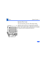
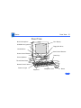
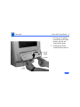
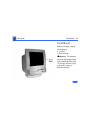
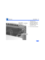
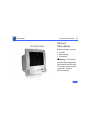
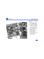
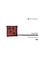
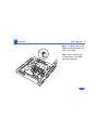
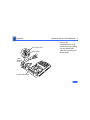
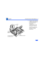
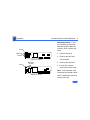
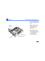
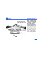
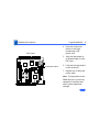
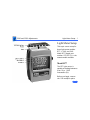
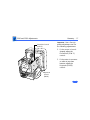
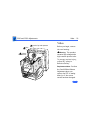
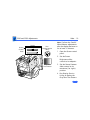
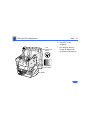
K Service Source
Power Macintosh/Performa
5260, 5280 Series
Power Macintosh 5260/100, 5260/120
International Performas 5260/120, 5280
K Service Source
Basics
Power Macintosh/Performa
5260, 5280 Series
Basics
System Overview - 1
System Overview
The Power Macintosh 5260 and 5280 design includes
expansion slots for 68040 LC communications and PDS
cards, as well as other video-in, video tuner, and video-out
options. Disk storage includes an IDE hard drive in a variety
of capacities and a trayloading CD-ROM drive.
Basics
5260/120 and 5280 - 2
5260/120 and 5280
The Performa 5260/120 is sold in Canada and Australia.
The Performa 5280 is sold in Japan. The Power Macintosh
5260/120 is sold in the United States and Canada.
The 5260/120 and 5280 models are similar to the
5260/100, but differ with these features:
• PowerPC 603e processor at 120 MHz clock frequency
• 16 MB of DRAM minimum (32-bit wide, 72-pin fastpaged mode, 80-nanosecond SIMMs)
• AppleCD 1200i CD-ROM
Basics
Service Strategy - 3
Service Strategy
Service the Power Macintosh/Performa 5000 series
through module exchange and parts replacements. Customers
can request on-site service from an Apple Authorized
Service Provider Plus (AASP+) or Apple Assurance. They
can also choose carry-in service from an Apple Authorized
Service Provider (AASP).
Ordering
AASPs planning to support the Power Macintosh/Performa
5000 series may purchase service modules and parts to
develop servicing capability. To order parts, use the
AppleOrder system, or refer to the “Service Price Pages.”
Large businesses, universities, and K-12 accounts must
provide a purchase order (PO) on all transactions, including
Basics
Service Strategy - 4
orders placed through the AppleOrder system. Service
Providers not enrolled in AppleOrder may fax their orders
to Service Provider Support (512-908-8125) or mail
them to
Apple Computer, Inc.
Service Provider Support
MS 212-SPS
Austin, TX 78714-9125
Warranty and AppleCare
These new computers are covered under the Apple One-Year
Limited Warranty. The AppleCare Service Plan is also
available. Service Providers are reimbursed for warranty
and AppleCare repairs made to these computers. For pricing
information, refer to the AppleCare section in the “Service
Price Pages.”
Basics
Service Strategy - 5
Diagnostics
Use MacTest Pro for Power Macintosh to perform
diagnostics on the Power Macintosh/Performa 5000 series.
Design for Serviceability
To access the floppy drive, CD-ROM drive, or front panel
control board, remove the drive and controls bezel. To
service the logic board, hard drive, or video options, remove
the I/O door. The logic board slides out from a connector
similar to the connector on Macintosh LC 630 and LC 500.
The CRT and degauss frame are matched at the factory and are
removed and replaced as a unit. The chassis harness is one
service module, including the metal chassis and logic board
connector with cables.
Basics
User Controls - 6
User Controls
User controls include
• Soft power-on control from keyboard
• Front-panel sound-control pushbuttons
• Front-panel brightness-control pushbuttons
• Optional infrared remote control
Basics
Internal Expansion Connections - 7
Internal Expansion Connections
Expansion connections on the logic board include
• 2 DRAM SIMM expansion slots
• LC Processor Direct Slot (PDS)
• Communications slot for modems and Ethernet
• Video-in slot for real-time video display, capture, and
overlay
• External video port
An expansion ribbon connector for an optional TV Tuner card
provides NTSC and PAL input from an external TV antenna or
cable.
Basics
Intelligent Device Electronics (IDE) Hard Drive - 8
Intelligent Device Electronics (IDE)
Hard Drive
The internal hard drive uses Intelligent Device Electronics
(IDE) technology, commonly used in DOS-compatible
systems. The IDE hard drive functions the same as a typical
SCSI hard drive. You must replace IDE drives like-for-like.
The IDE drive does not affect SCSI ID selections or SCSI
termination schemes. Seven external SCSI devices may be
daisy-chained through the external SCSI port.
Basics
Processor Direct Slot (PDS) - 9
Processor Direct Slot (PDS)
The LC-PDS is compatible with the PDS in the Macintosh LC
family of computers, but it is not a true PDS. Like the
expansion slot in the other models in the Power Macintosh
and Performa 5000 series, this expansion slot supports
many PDS cards designed to operate with the MC68030 bus.
While the I/O expansion slot accepts PDS cards designed for
the Macintosh LC family of computers, some of those cards
do not work. PDS cards designed to interact with the main
processor—to provide, for example, a RAM cache or an
FPU—will not work in the I/O expansion slot.
Basics
Video-In Card - 10
Video-In Card
The Video-In Card is an optional card included with the Apple
Video System. It allows users to digitize video from the TV
Tuner, MPEG Card, and external composite or S-video
inputs. It accepts NTSC, PAL, or SECAM format video and
also provides stereo audio inputs.
Install the Video-In Card into the dedicated 60-pin, 1.75inch video slot.
Basics
MPEG Card - 11
MPEG Card
The MPEG Card is an optional card included with the Apple
MPEG Media System. The MPEG Card requires that the
Video-In Card be installed. It provides hardware
decompression for MPEG movie files, enabling full-screen
(through pixel doubling), 30-frames-per-second, 24-bit
video playback with 16-bit audio. After the MPEG movies
are compressed, they are sent to the Video-In Card, which
converts the data into digital format for output to the screen.
Install the MPEG Card in the processor direct slot.
Basics
TV Tuner Module - 12
TV Tuner Module
The TV Tuner, an optional module included with the Apple
TV/Video System, turns the computer into a television
receiver. The TV Tuner requires the Video-In Card, which is
also included with the Apple TV/Video System. The TV Tuner
receives incoming television signals from cable or antenna
television inputs, and then sends the information to the
Video-In Card, which converts the data for display on the
screen. In the United States, only NTSC is supported, but
PAL and SECAM are available internationally.
Install the TV Tuner in a separate bay at the rear of the
computer, below the logic board.
Basics
TV/FM Radio Tuner Card - 13
TV/FM Radio Tuner Card
The TV/FM radio tuner card turns the computer into a
television and FM radio receiver, complete with remote
control. An expansion ribbon connector for the optional
TV/FM radio tuner card provides NTSC and PAL input from
an external TV antenna or cable. Change channels by typing
the channel number on the keyboard or with the remote
control. Switch between the current and previous channel by
pressing the Tab key. The computer displays the userassigned channel name on the picture in the video window.
Apple Video Player software supports the TV/FM tuner card.
The user can disable channels and require a password to
access the disabled channels. Users can also capture or
freeze a single frame of video or record a segment of video as
a QuickTime movie. It isn’t possible to resize the window
while recording a movie.
Basics
TV/FM Radio Tuner Card - 14
The TV picture is in its own window on the desktop, and the
default size of the window is 320x240 pixels. The picture
can be resized from 160x120 pixels up to 640x480 pixels.
The resolution of the picture does not increase at larger
window sizes, but the image is expanded by doubling the
pixel size or by two-dimensional linear interpolation.
The TV signal is carried in YUV format for improved picture
clarity. The YUV format is 16-bit, with 8 bits for the Y
(luminance) channel and 8 bits for the U and V
(chrominance) channels to share by multiplexing. The
picture is clearer because the YUV format carries more
levels of luminance information.
Basics
TV/FM Radio Tuner Card - 15
The card is available in versions for NTSC, PAL, and SECAM
television systems. The features of the TV tuner include the
following:
• Remote tuner for 181 broadcast and cable channels (U.S.
version)
• Coaxial connector for TV antenna or cable input (F-type
connector in U.S. and Japanese version, IEC-type
connector in Europe)
• TV picture in a resizable and movable window
• YUV format for improved clarity
• Closed captioning and teletext support
• Software password protection
• Automatic and manual channel programming
• Single remote control for TV and for playback of audio
CDs
Basics
TV/FM Radio Tuner Card - 16
The features of the FM radio tuner include the following:
• FM radio frequencies received and displayed
• Stations scanned and searched up and down the frequency
spectrum
• Step frequency
• DX mode to tune out harmonic spillover from other
stations
• Stereo/mono station indicator
• Preset station programming
Basics
External Video Connector - 17
External Video Connector
The External Video Connector is an optional module that
provides the computer with video output (mirroring).
Install the External Video Connector in a dedicated 3/4inch, 22-pin slot on the logic board.
Basics
Apple Presentation System - 18
Apple Presentation System
The Apple Presentation System (APS) is an external module
that uses the 15-pin video output connector on the
computer, and then provides a video signal for a separate
television display or for recording on a VCR. The APS
supports video mirror mode, where the image on the
television display is the same as the computer’s primary
video monitor. The APS is required for video mirroring.
Basics
The Cuda Chip - 19
The Cuda Chip
The Cuda is a microcontroller chip. Its function is to
• Turn system power on and off
• Manage system resets from various commands
• Maintain parameter RAM (PRAM)
• Manage the Apple Desktop Bus (ADB)
• Manage the real-time clock
Many system problems can be resolved by resetting the Cuda
chip. Press the Cuda reset button on the logic board to reset
the Cuda chip. See the 5400 or 5260/5280 logic board
diagrams later in this chapter to locate the Cuda reset
button.
Basics
CRT and Degauss Frame - 20
CRT and Degauss Frame
The CRT and degauss frames are precisely matched at the
factory and must be removed and replaced as a unit.
Basics
Front View - 21
Front View
Color Display
Built-In Microphone
CD-ROM Drive (optional)
Floppy Disk Drive
CD-ROM Drive
Sound Control Buttons
Screen Control Buttons
Power Key
Stereo Speakers
Tilt-and-Swivel Base
Remote Control Sensor
Power-On Light
Keyboard
Headphone Jack
Mouse
Basics
Rear View - 22
Rear View
Microphone
Assembly
Rear
Housing
Power
Supply
Assembly
Analog
Board
Assembly
CRT Video
Board
Assembly
Floppy
Drive
CD ROM
Drive
Hard
Drive
Tilt-Swivel
Assembly
Logic
Board
TV
Tuner
Board
I/O Panel
Assembly
Basics
I/O Panel - 23
I/O Panel
Video Input
Access Cover
ADB Printer Modem
Port Port
Port
External Video
Output
Connector Cover
SCSI Sound Sound
Port Input Output
Port
Port
Communication
Card Access Cover
PDS
Cover
Basics
5260/5280 Logic Board - 24
5260/5280 Logic Board
Monitor-Out Slot
Battery
Video-In
Slot
Cuda Reset Button
Communications
Card Slot
ROM
Slot
Processor/
Heatsink
PDS
DRAM
SIMM Slot
K Service Source
Specifications
Power Macintosh/Performa
5260, 5280 Series
Specifications
Processor - 1
Processor
CPU
5260/100
PowerPC 603e processor
100 MHz
5260/120, 5280
PowerPC 603e processor
120 MHz
Addressing
64-bit PowerPC bus
Specifications
Memory - 2
Memory
DRAM
16 MB DRAM, minimum
Expandable to 64 MB (72-pin, 80 ns or faster SIMMs)
Frame Buffer
1 MB DRAM on board, for video support
ROM
4 MB
Cache Memory
256K Level 2
Specifications
Disk Storage - 3
Disk Storage
Floppy Drive
1.4 MB Apple SuperDrive Manual Insert
Hard Drive
800 MB, 1.2 GB, or 1.6 GB IDE hard drive
CD-ROM Drive
5260/100
Standard AppleCD 600i drive
5260/120, 5280
AppleCD 1200i drive
Specifications
I/O Interfaces - 4
I/O Interfaces
Serial
Two RS-232/422 serial ports for modem and printer
(mini DIN-8 connectors) LocalTalk supported
SCSI
One external SCSI port (DB-25 connector)
Supports up to seven SCSI devices
Apple Desktop Bus
One Apple Desktop Bus (ADB) port (mini DIN-4 connector)
Sound Input
Built-in microphone for monaural sound input.
Sound-input port for microphone or line input. The port accepts
stereophonic input, but sound is combined into monophonic
sound for play-through or recording.
Specifications
Sound Output
External Video
Connector
I/O Interfaces - 5
Two stereophonic sound output ports, level nominally 0.5 V RMS
into 39 ohms
One front headphone jack, one rear stereo mini phonejack
Internal stereo speakers
One DB-15 mirror video out connector using optional video
connector kit. This feature provides “mirroring” (or display
of the system’s monitor’s screen on a presentation screen).
(Note: the external video display is presentation only. It cannot
be manipulated directly by mouse or other input signals.)
Specifications
I/O Interfaces - 6
Video-in Slot
One 60-pin video-in slot for optional expansion card providing
real-time video display, capture, and overlay.
TV Tuner
One 10-pin port for TV Tuner card
Communications
One 112-pin internal expansion slot for modem or Ethernet card
(68040-bus configuration)
Processor-Direct Slot
One 96/114-pin internal expansion slot for LC-compatible
processor-direct card
Controls
Soft-power control from keyboard
Front panel pushbutton control for sound volume
Front panel pushbutton control for display brightness
Infrared remote control option
Specifications
I/O Devices - 7
I/O Devices
Keyboard
Apple Extended Keyboard II, AppleDesign (other ADB keyboards
supported)
Mouse
Apple Desktop Bus Mouse
Mechanical tracking, optical shaft, or contact encoding
Microphone
Integrated microphone for monophonic sound input
Speaker
Integrated stereo speakers capable of delivering 16-bit stereo
sound
Specifications
Sound and Video - 8
Sound and Video
Sound Generator
Records at 11-kHz or 22-kHz sample rate
Plays back at 22-kHz sample rate
Two speakers with enhanced stereo sound
Allows playback and recording of ordinary audio compact discs
(CDs)
16-bit monophonic sound input
16-bit stereophonic sound output (16-bit CD stereophonic
playback), level nominally 0.5 V RMS into 39 ohms
Sound-input port for microphone or line input; accepts
stereophonic input, but sound is combined into monophonic
sound for play-through or recording
Two stereophonic sound output ports, level nominally 0.5 V RMS
into 39 ohms
Internal speaker muted when a plug is inserted into an output jack
Specifications
Built-in Video
Display
Sound and Video - 9
Dot Pitch: 0.28 mm
Vertical Frequency: 66.7 Hz
Active Raster Size (nominal): 9.5 in. by 7.3 in. (240 mm by 185
mm)
White Point: 9,300° K
Shipping Brightness (nominal): 25-foot lamberts
14-in. Shadow Mask display (12.8-in. viewable image)
Phosphor (aluminized): P22 (red, green, blue)
Phosphor CIE Coordinates:
Red
x = 0.643 ± 0.020, y = 0.324 ± 0.020
Green x = 0.301 ± 0.020, y = 0.606 ± 0.020
Blue
Video Modes
x = 0.142 ± 0.015, y = 0.056 ± 0.015
Supports 640x480 resolution with 16-bit color.
Specifications
Monitor Timings
640x480 Resolution
at 60 Hz
Horizontal Timing
Vertical Timing
Sound and Video - 10
Back porch: 96 dots
HSYNC: 64 dots
Front Porch: 64 dots
1 dot: 33.06878 ns
1 H: 28.5714 ms
1/dot: 30.24 MHz
Back porch: 39 H
VSYNCH: 3 H
Front Porch: 3 H
1 H: 28.5714 ms
1/H: 35.000 k Hz
1 V: 15.000 ms
Specifications
Sound and Video - 11
Monitor Timings
640x480 Resolution
at 66.67 Hz
Horizontal Timing
Vertical Timing
Back Porch: 96 dots
H SYNC: 64 dots
Front Porch: 64 dots
1 dot: 33.06878 n
1 H: 28.5714 ms
1/dot: 30.24 MHz
Back Porch: 39 H
V SYNC: 3 H
Front Porch: 3 H
1 H: 28.5714 ms
1/H: 35.000 kHz
1V: 15.000 ms
1/V: 66.666 Hz
Specifications
Sound and Video - 12
Monitor Timings
800x600 Resolution
at 60 Hz
Horizontal Timing
Vertical Timing
Back Porch: 88 dots
H SYNC: 128 dots
Front Porch: 40 dots
1 dot: 25.000 ns
1 H: 26.4 ms
1/dot: 40.000 MHz
Back Porch: 23 H
V SYNC: 4 H
Front Porch: 1 H
1 H: 37.879 ms
1/H: 16.58 kHz
1 V: 60.3165 ms
1/V: 60.3165 Hz
Specifications
Sound and Video - 13
Monitor Timings
800x600 Resolution
at 72 Hz
Horizontal Timing
Vertical Timing
Back Porch: 64 dots
H SYNC: 120 dots
Front Porch: 56 dots
1 dot: 20.000 ns
1 H: 20.800 ms
1/dot: 50.000 MHz
Back Porch: 23 H
V SYNC: 6 H
Front Porch: 37 H
1 H: 20.800 ms
1/H: 48.077 kHz
1 V: 13.853 ms
1/V: 72.186 Hz
Specifications
External Video
Connector
(Optional)
Sound and Video - 14
Supports video mirroring on the following external monitors (at
product introduction):
Supports video mirroring on the following external monitors (at
product introduction) with 640x480 resolution: Macintosh
13" Color Display, Apple Color Plus 14" Display, Macintosh
Color Display, Apple Performa Plus Display, Apple Multiple
Scan 14 Display, Apple Multiple Scan 15 Display, Apple
Multiple Scan 17 Display, Apple Multiple Scan 20 Display,
AppleVision 1710AV Display, Apple Multiple Scan 1705
Display, VGA monitors (a plug adapter may be required)
Specifications
Electrical - 15
Electrical
Line Voltage
100–240 VAC
Frequency
47–63 Hz
Power
240 W maximum
Surge Voltage: 300 V RMS for 100 ms
Peak Inrush Current: 40 A pk
Current: 4.0 A maximum for all line and load conditions
Power: 220 W maximum for all line and load conditions
Specifications
Physical - 16
Physical
Dimensions
Weight
Height: 17.5" (445 mm)
Width: 16" (406 mm)
Depth: 15.1" (383 mm)
Without CD-ROM: 17 lb.
With CD-ROM: 19 lb. (21.15 kg)
Weight varies with options
Specifications
Environmental - 17
Environmental
Temperature
Operating: 50°–104° F (10°–40° C)
Transit (72 hours): –40° F to +149° F (–40° C to +65° C)
Storage (6 months): –40° F to +116° F (–40° C to +47° C)
Humidity
Noncondensing, 20–95%
Altitude
0–10,000 ft. (0–3,000 m)
K Service Source
Troubleshooting
Power Macintosh/Performa
5260, 5280 Series
Troubleshooting
General - 1
General
The Symptom Charts included in this chapter will help you
diagnose specific symptoms related to your product. Because cures
are listed on the charts in the order of most likely solution, try
the first cure first. Verify whether the product continues to
exhibit the symptom. If the symptom persists, try the next cure.
( Note: If you have replaced a module, reinstall the original
module before you proceed to the next cure.)
If you are not sure what the problem is, or if the Symptom Charts
do not resolve the problem, refer to the Flowchart for the product
family.
For additional assistance, contact Apple Technical Support.
Troubleshooting
First Checklist - 2
First Checklist
Jitter, faint lines, or screen movement can be caused by external
interference such as electronic devices and fluorescent lights.
Move the unit to another room or building to help determine if
external interference is the source of the problem.
A misadjusted screen can mimic the same symptoms as analog
board or CRT failures. By performing the adjustment procedures,
you might determine if one or more of the adjustments is the cause
of the problem.
Troubleshooting
Symptom Charts/System - 3
Symptom Charts
System
System
intermittently
crashes or hangs
1
2
3
4
Verify that system software is version 7.5 or later.
Verify that software is compatible with system.
If Ethernet card is installed, verify that it is fully seated.
Check that system has enough memory installed for
application.
System does not start
up
1
2
3
4
Reset logic board. Refer to Additional Procedures.
Replace power supply.
Check power cord connection.
Replace logic board. Retain customer’s SIMMs.
Troubleshooting
Symptom Charts/System - 4
System will not start
up from keyboard,
but will start up from
rear power switch
1
2
Verify keyboard as known-good.
Replace analog board.
System continually
restarts after
Shutdown from
Special menu
1
2
Verify keyboard as known-good.
Replace analog board.
Flashing “?”
appears at startup in
system with vacant
PDS and
communications slots
1
Diagnose hard drive with Disk First Aid included on Power
Macintosh CD-ROM.
Perform repairs, and then go to step 4.
If repairs are impossible, back up drive, reformat with
Drive Setup 1.0.3, and then go to step 4.
Update driver using Drive Setup 1.0.3.
Perform clean install of system software.
2
3
4
5
Troubleshooting
Menu bar constantly
flashes or system
constantly beeps
Symptom Charts/System - 5
1
2
3
Verify that front-panel control buttons are not jammed.
Verify “mute” is not selected in the Sound control panel.
Reseat drive bezel and front-panel control board.
Troubleshooting
Symptom Charts/Audio - 6
Audio
Distorted or garbled
sound from both
speakers
Replace analog/video board assembly.
Distorted or garbled
sound from one
speaker
1
2
Sound distortion
with MPEG board
installed
Replace MPEG board with modified MPEG board. A modified
board should have a jumper present from U5 Pin 2 to D1 Pin 1.
No sound output from
speakers
1
2
3
Replace defective speaker.
Replace analog/video board assembly.
Check sound source.
Check that speaker cable at connector P601 on analog board
is plugged in and not defective.
Reseat drive bezel and front-panel control board.
Troubleshooting
Crackling noise is
present when
playing sounds other
than system beeps
and not in “play
through” mode
Symptom Charts/Audio - 7
1
2
If static noise varies while adjusting volume with Sound
control panel, use Audio Volume Extension 1.1 or later.
Note: Audio Volume Extension is available from standard
Apple software update sites.
Replace logic board.
Troubleshooting
Symptom Charts/Video - 8
Video
Screen is black, too
dark, or too bright;
audio and drive
operate
1
2
3
4
5
6
7
Screen is bright and
audio is present, but
no video information
is visible
1
2
Adjust contrast button on front bezel.
Adjust brightness. Use Screen control panel.
Check yoke cable connection.
Perform video adjustments. Refer to “Video” in
Adjustments chapter.
Replace analog/video board assembly.
Replace power supply board.
Replace CRT.
Perform video adjustments. Refer to “Video” in
Adjustments chapter.
Replace analog/video board assembly.
Troubleshooting
Video will not play
or system hangs
when attempting to
run video in units
with MPEG card
Symptom Charts/Video - 9
1
2
If chip at location U12 on MPEG card displays number
341SO205, check all connections.
If chip at location U12 on MPEG card does not display
number 341SO205, replace MPEG card.
Single vertical or
horizontal line is
displayed
1
2
Replace analog/video board assembly.
Replace CRT.
Predominant color
tint or color cannot
be adjusted
1
Verify that video board is securely connected to CRT
socket.
Check cable connections to analog/video board.
Replace the RGB cable.
Replace analog/video board assembly. Perform video
adjustments (refer to “Video” in Adjustments chapter).
Replace CRT.
2
3
4
5
Troubleshooting
Out of convergence
(color bleeds from
text or lines)
Symptom Charts/Video - 10
1
2
This problem rarely indicates a defective module. Some
misconvergence is normal, especially around edges of screen.
Contact Apple Technical Support if you’re uncertain whether
misconvergence is within specification.
Replace analog/video board assembly.
Black screen spots
(burnt phosphors)
Replace CRT.
Picture breaks into
diagonal lines, or
picture rolls
vertically or
horizontally
1
2
Perform geometry adjustments. Refer to “Geometry” in
Adjustments chapter.
Replace analog/video board assembly.
Troubleshooting
Screen jitters or
flashes
Symptom Charts/Video - 11
1
2
3
Out of focus
1
2
3
Refer to “First Checklist” in Troubleshooting chapter. Move
electrical devices (other monitors, scanners, and so on) away
from monitor. Temporarily shut off all fluorescent lights in
area.
Move unit to another room or building and check if symptom
persists.
Replace analog/video board assembly.
Perform focus adjustment. Refer to “Focus” in Adjustments
chapter.
Check for proper screen luminance. If luminance is off,
perform Cutoff and White Balance procedures. Refer to
“Video” in Adjustments chapter.
Replace analog/video board assembly.
Troubleshooting
Symptom Charts/Video - 12
Linearity bad (size of
text/graphics differs
at top, bottom, or
sides of screen)
Replace analog/video board assembly.
Raster tilted or
shifted
1
2
3
Refer to “First Checklist” in Troubleshooting chapter. Move
metal objects away from monitor.
Perform appropriate geometric adjustments. Refer to
“Geometry” in Adjustments chapter.
Replace analog/video board assembly.
Troubleshooting
Raster distorted
(barrel-shaped,
corners not square,
stretched or
compressed at top of
display, or sides not
perpendicular)
Symptom Charts/Video - 13
1
2
3
4
Raster not centered
1
2
Refer to “First Checklist” in Troubleshooting chapter.
Perform appropriate geometric adjustments. Refer to
“Geometry” in Adjustments chapter.
Install monitor-adjustment cable and use on-screen video
adjustment controls to eliminate distortion. Based on video
tolerances, some distortion is allowed and setting need not be
perfect. Contact Apple Technical Support if you’re unsure
about tolerance level.
Replace analog/video board assembly.
Adjust horizontal or vertical shift control. Refer to
Adjustments chapter.
Refer to “First Checklist” in Troubleshooting chapter.
Troubleshooting
Screen has white
areas with blotches of
color
Symptom Charts/Video - 14
1
2
3
Refer to “First Checklist” in Troubleshooting chapter.
Because this purity problem can be caused by magnetic
fields, move unit to another location.
Degauss display with manual degaussing coil. (Degaussing
coils can be purchased at most major electronic parts
stores.)
Troubleshooting
Symptom Charts/Floppy Drive - 15
Floppy Drive
Audio and video are
present, but internal
floppy drive does not
operate
1
2
3
Replace bad disk with known-good disk.
Replace floppy drive.
Replace logic board. Retain customer’s SIMMs.
Disk ejects; display
shows icon with
blinking “X”
1
2
3
Replace bad system disk with known-good system disk.
Replace floppy drive.
Replace logic board. Retain customer’s SIMMs.
Unable to insert disk
all the way
1
To eject previously inserted disk, insert opened paper clip
into hole beside floppy drive.
Switch off system and hold mouse button down while
switching system on (to complete eject cycle).
Replace floppy drive.
2
3
Troubleshooting
Disk does not eject
Internal floppy drive
runs continuously
Symptom Charts/Floppy Drive - 16
1
2
3
Insert opened paper clip into hole beside floppy drive.
Switch off system and hold mouse button down while
switching system on (to complete eject cycle).
Replace floppy drive.
1
2
3
Replace bad disk with known-good disk.
Replace floppy drive.
Replace logic board. Retain customer’s SIMMs.
Troubleshooting
Symptom Charts/Hard Drive - 17
Hard Drive
Internal or external
hard drive does not
operate
1
2
3
4
5
6
Verify that all hard drive connections are secure.
Verify that external drive is properly terminated.
Reseat logic board.
Replace internal IDE hard drive.
Replace chassis/wiring harness.
Replace logic board. Retain customer’s SIMMs.
Internal hard drive
runs continuously
1
2
3
4
Verify that system software is version 7.5 (or later).
Replace hard drive cable.
Replace internal hard drive.
Replace logic board. Retain customer’s SIMMs.
Hard drive not found
when booted from CDROM drive
Use Drive Setup 1.03 to attempt mounting the hard drive.
Troubleshooting
Flashing ? appears at
startup in 5260/
100 with 1.6 GB ATA
hard drive (p/n
661-1107), and may
be corrected with
restart.
Symptom Charts/Hard Drive - 18
1
2
3
Be sure system software is not corrupted. See the Software
Troubleshooting document in the HW-SW Procedures topic
under the Troubleshooting tab on the Service Source CD
startup screen.
Remove the 1.6 GB ATA hard drive and look at the serial
number on the bar code label.
If serial number is within range XXX6 0 9 9 XXXXX to
XXX6 1 3 1 XXXXX, replace hard drive.
Troubleshooting
Symptom Charts/CD-ROM Drive - 19
CD-ROM Drive
CD-ROM drive does
not accept disc
1
2
3
Exchange compact disc (if disc is dirty or damaged).
Replace CD-ROM drive mechanism.
Replace SCSI data cable.
Volume control does
not operate correctly
1
2
3
4
Check Sound control panel setting.
Check front-panel controls.
Reseat the drive and control bezel.
Verify that the front-panel control board is completely
installed.
Reseat CD adapter connector.
Replace CD adapter connector.
Replace CD-ROM drive.
Replace chassis/wiring harness.
5
6
7
8
Troubleshooting
Symptom Charts/CD-ROM Drive - 20
Computer cannot
mount known-good
CD-ROM drive
1
2
When an internal and
external SCSI device
are present, only one
starts up
1
CD Plus (CD+)
format CD-ROM disc
causes stuttering
sound, and may not
mount.
Replace CD-ROM drive.
3
4
2
3
Reseat CD-ROM drive adapters.
Check SCSI ID setting. (Internal CD-ROM drive was
originally set to 3 at factory.)
Replace CD-ROM drive.
Replace chassis/wiring harness
Verify that ID switch setting on external SCSI device is
higher than 0. Verify that ID switch setting on external SCSI
device does not duplicate ID switch settings on other external
SCSI devices.
Replace terminator on external SCSI device.
Replace SCSI select cable.
Troubleshooting
Eject button sticks.
Symptom Charts/CD-ROM Drive - 21
Replace the front bezel.
Troubleshooting
Symptom Charts/Peripheral - 22
Peripheral
Cursor does not move
Cursor moves, but
clicking mouse
button has no effect
1
2
3
4
5
Restart system.
Check mouse connection.
If mouse was connected to keyboard, connect mouse to rear
ADB port and disconnect keyboard. If mouse works, replace
keyboard. If mouse does not work in ADB port, replace mouse.
Reseat logic board.
Replace logic board. Retain customer’s SIMMs.
1
2
3
Replace mouse.
Reseat logic board.
Replace logic board. Retain customer’s SIMMs.
Troubleshooting
Cannot double-click
to open application,
disk, or server
Symptom Charts/Peripheral - 23
1
2
3
5
Remove extra system files on hard drive.
Check mouse speed on Control Panel.
Unplug 4.5 battery, wait 20 seconds, plug in battery, and
restart computer.
If mouse was connected to keyboard, connect mouse to rear
ADB port and disconnect keyboard. If mouse works, replace
keyboard. If mouse does not work in ADB port, replace mouse.
Replace logic board. Retain customer’s SIMMs.
1
2
3
4
5
Verify that system software is version 7.5 or later.
Check keyboard connection to ADB port.
Replace keyboard.
Reseat logic board.
Replace logic board. Retain customer’s SIMMs.
4
No response to any
key on keyboard
Troubleshooting
Symptom Charts/Peripheral - 24
Known-good
StyleWriter,
ImageWriter, or
ImageWriter II does
not print
1
2
Known-good
LaserWriter does not
print
1
2
3
Verify that Chooser and Control Panel are set correctly.
Verify that printer driver and system software are not
corrupt.
Replace printer interface cable(s).
Doesn’t recognize
SCSI device
1
2
3
Check for proper SCSI termination.
Check that the SCSI cable is good and firmly connected.
Check the SCSI device manual for required software.
3
4
5
6
Verify that Chooser and Control Panel are set correctly.
Verify that printer driver and system software are not
corrupt.
Verify system software is version 7.5 or later.
Check printer DIP switches.
Replace printer interface cable.
Replace logic board. Retain customer’s SIMMs.
Troubleshooting
Symptom Charts/Miscellaneous - 25
Miscellaneous
Clicking, chirping,
or thumping sound
1
2
Replace analog board.
Replace logic board. Retain customer’s SIMMs.
Smoke or Odor
Present
1
2
3
Replace Analog board.
Replace Power Supply.
Replace Logic Board.
No video, no audio, and
no drive operation
1
2
3
4
5
Connect power cord.
Switch power on.
Replace power cord.
Replace analog board.
Replace logic board. Retain customer’s SIMMs.
Troubleshooting
Symptom Charts/Miscellaneous - 26
Screen shows “Sad
Macintosh” icon and
black vertical lines;
screeching sound
1
2
Replace RAM SIMMs on logic board.
Replace logic board. Retain customer’s SIMMs.
Rattling sound at
startup in system
with Apple External
Video Connector
Press or fold Apple External Video cable to prevent it from
contacting fan blades.
Headphone jack does
not operate correctly
1
2
3
Verify that headphone jack is seated properly.
Replace front panel control board.
Replace chassis/wiring harness.
Troubleshooting
“Sad Macintosh” icon
Symptom Charts/Miscellaneous - 27
1
2
3
4
5
6
No sound from
known-good external
speakers
1
2
3
4
Verify that no disc is in CD-ROM drive.
Disconnect all external SCSI devices and attempt to restart
computer.
Disconnect internal SCSI device and attempt to start
computer with known-good floppy disk.
Replace bad SCSI drive with known-good SCSI drive.
Replace RAM SIMMs on logic board.
Replace logic board. Retain customer’s SIMMs.
Check that volume is turned on (manually or through Control
Panel).
Verify that headphones are unplugged.
Verify that speaker connectors are properly connected.
Replace logic board. Retain customer’s SIMMs.
Troubleshooting
System with internal
modem unable to
recognize graphics or
Ethernet card in
communications slot
Symptom Charts/Miscellaneous - 28
1
2
Replace internal modem.
Replace graphics or Ethernet card.
K Service Source
Take Apart
Power Macintosh/Performa
5260, 5280 Series
Take Apart
Drive and Control Bezel - 1
Drive and Control
Bezel
No preliminary steps are
required before you begin
this procedure.
Take Apart
Drive and Control Bezel - 2
1
2
Placing your fingertips
in the holes of the finger
latches, pull the two
finger latches down.
Swing the drive and
control bezel up and off.
Take Apart
Drive and Control Bezel - 3
Replacement Note: Insert
the drive bezel hinge tabs
behind the upper corners of
the front bezel opening.
Swing the drive bezel down
until it snaps closed.
Take Apart
Floppy Drive - 4
Floppy Drive
Before you begin, remove
the drive and control bezel.
Caution: Review the ESD
precautions in Bulletins/
Safety.
Take Apart
Floppy Drive - 5
1
Pull up the release
latch, and pull out the
floppy drive far enough
to reach the ribbon cable
connector.
Take Apart
Floppy Drive - 6
2
Disconnect the floppy
drive from the floppy
drive cable.
Note: Remove the drive
carrier if you are replacing
the floppy drive.
Note: Because screw
placement varies according
to the type of drive used with
the carrier, note the
placement of the screws
before removing them.
Retain the carrier and
screws, and install them on
the new floppy drive.
Take Apart
Floppy Drive - 7
3
4
Remove the four
mounting screws.
Remove the carrier from
the floppy drive.
Take Apart
CD-ROM Drive - 8
CD-ROM Drive
Before you begin, remove
the following:
• Drive and control bezel
• Floppy drive
Note: The CD-ROM drive is
optional.
Caution: Review the ESD
precautions in Bulletins/
Safety.
Take Apart
CD-ROM Drive - 9
Push up the release latch
and pull the CD-ROM drive
from the chassis.
Note: You may need to use
some initial force to
disconnect the CD-ROM
drive from the internal
chassis/wiring harness.
Take Apart
CD-ROM Drive - 10
Note: Perform the following
steps only if you are
replacing the CD-ROM
drive.
1
2
3
Disconnect the CD-ROM
audio adapter from the
drive.
Disconnect the SCSI
adapter
Remove the four
mounting screws and
carrier from the CDROM drive.
Take Apart
CD-ROM Drive - 11
Replacement Note: Retain
the carrier, screws, and
adapters for installation on
the new drive.
Replacement Caution:
Before replacing the SCSI
adapter, verify that the SCSI
drive connector pins are not
bent.
Take Apart
Front Panel Control Board - 12
Front Panel
Control Board
Before you begin, remove
the drive and control bezel.
Caution: Review the ESD
precautions in Bulletins/
Safety.
Take Apart
Front Panel Control Board - 13
Caution: Be sure to grip the
front panel in the area
shown to avoid harming
circuit tracings.
1
2
Using needle-nose
pliers, grip the front
edge of the front-panel
control board.
Pull firmly and slide
the front panel control
board out far enough to
reach the ribbon cable
connector.
Take Apart
Front Panel Control Board - 14
3
Disconnect the cable
from the front-panel
control board.
Replacement Note: Using a
flat-blade screwdriver,
press the front-panel
control cable back and down.
Take Apart
Front Panel Control Board - 15
Replacement Note: Tilt the
board up slightly to insert it
into the guide rails.
Take Apart
Front Panel Control Board - 16
Replacement Note: The
front edge of the reinstalled
front-panel control board
must be flush with the front
edge of the plastic chassis.
Take Apart
I/O Door - 17
I/O Door
No preliminary steps are
required before you begin
this procedure.
Take Apart
I/O Door - 18
1
Remove the two security
screws.
Take Apart
I/O Door - 19
2
3
Using your fingertips,
pull the two finger
latches down.
Swing the door up and
off.
Replacement Note: Align the
I/O door hinge tabs and slide
the door up into position.
Swing the door down until it
snaps closed.
Take Apart
Logic Board - 20
Logic Board
Before you begin, remove
the I/O door.
Caution: Review the ESD
precautions in Bulletins/
Safety.
Take Apart
Logic Board - 21
1
2
Swing out the handle
from its storage
position.
Pull out the logic board.
Note: When installing
cards, cover the two screws
(for fan support and ground
thermistor mounting) with
tape. These screws are below
the upper chassis, in the
area of the logic board.
Stretching a length of
strong tape (fiberreinforced, if possible)
from front to back over the
screws protects cables from
damage.
Take Apart
Logic Board - 22
Note: Perform the following
steps only if you are
replacing a defective logic
board.
3
Remove the two Phillips
screws that secure the
fence to the solder side of
the logic board.
Take Apart
Logic Board - 23
4
5
Using a hex nut driver,
remove the two hex nuts
that secure the logic
board fence to the SCSI
connector.
Separate the logic board
fence from the logic
board.
Take Apart
Logic Board - 24
Replacement Note: Verify
that the flange on the logic
board fence is properly
aligned with the mini-DIN
shield.
Take Apart
Logic Board - 25
Replacement Note: Align
the flange around the miniDIN shield first, then swing
the rest of the logic board
fence into place.
Take Apart
Rear Housing - 26
Rear Housing
Before you begin, remove
the I/O door.
This product
contains high voltage and a
high-vacuum picture tube.
To prevent serious injury,
review CRT safety in
Bulletins/Safety.
±Warning:
Take Apart
Rear Housing - 27
1
Pry off the two screw
covers on each side of the
rear housing.
Tip:
Pry up from the
rear edge of the screw
cover.
Take Apart
Rear Housing - 28
2
Remove the three torx
screws on each side of
the rear housing.
Take Apart
Rear Housing - 29
3
This step
exposes high voltage
components. Follow CRT
safety precautions.
±Warning:
Slide the rear housing
back and off.
Take Apart
Front Bezel - 30
Front Bezel
Before you begin, remove
the following:
• I/O door
• Rear housing
This product
contains high voltage and a
high-vacuum picture tube.
To prevent serious injury,
review CRT safety in
Bulletins/Safety.
±Warning:
Take Apart
Front Bezel - 31
1
2
.Disconnect the
microphone cable and
guide the cable to the
microphone side of the
metal CRT frame.
Pull off the front bezel.
Take Apart
Front Bezel - 32
Replacement Note: Guide
the microphone cables
through the plastic
retainers before replacing
the front bezel.
Take Apart
Internal Microphone - 33
Internal
Microphone
Before you begin, remove:
• I/O door
• Rear housing
• Front bezel
This product
contains high voltage and a
high-vacuum picture tube.
To prevent serious injury,
review CRT safety in
Bulletins/Safety.
±Warning:
Take Apart
Internal Microphone - 34
LIft off the microphone.
Replacement Note: Guide
the microphone cable
through the plastic cable
retainers.
Take Apart
Rear EMI Shield - 35
Rear EMI Shield
Before you begin, remove
the following:
• I/O door
• Front bezel
• Rear housing
Warning: This product
contains high voltage and a
high-vacuum picture tube.
To prevent serious injury,
review CRT safety in
Bulletins/Safety.
±
Take Apart
Rear EMI Shield - 36
1
Remove the three screws
from the power supply
side of the EMI shield.
Take Apart
Rear EMI Shield - 37
2
3
4
Remove the three screws
from the analog board
side of the EMI shield.
Remove the two screws
from the top of the EMI
shield.
Remove the two screws
from the rear of the EMI
shield.
Take Apart
Rear EMI Shield - 38
5
Pull back the EMI shield
and remove it.
Take Apart
Speakers - 39
Speakers
Before you begin, remove
the following:
• I/O door
• Rear housing
• Front bezel
Take Apart
Speakers - 40
1
Press the tab and release
the speaker from the
chassis slot.
Take Apart
Speakers - 41
2
Tilt the speaker and
remove it.
Take Apart
Speakers - 42
Replacement Note:
• The plastic speakers are
printed “right” and
“left.” Place the
speakers accordingly as
you face the monitor.
• Guide the wire connecting
the speakers in the
channel between the
monitor and chassis.
• Be careful not to crimp
the speaker wire as you
guide it from the speaker
to its analog board
connection.
Take Apart
Hard Drive - 43
Hard Drive
Before you begin, remove
the I/O door.
Caution: Review the ESD
precautions in Bulletins/
Safety.
Take Apart
Hard Drive - 44
1
2
Using the convenience
pull tab, disconnect the
IDE data cable from the
hard drive connector.
Disconnect the power
cable.
Take Apart
Hard Drive - 45
3
Using needle-nose
pliers, pull up the
release latch and slide
the IDE hard drive from
the chassis.
Replacement Caution: Some
hard drives have sharp edges
near the cable connector that
can rub and, therefore,
damage the cable. Avoid
rubbing the cable against the
edge of the drive.
Take Apart
Hard Drive - 46
Note: Perform the following
steps only if you are
replacing the hard drive.
Note: Notice the placement
of the carrier and screws
before removing them.
Retain the carrier and
screws, and install them on
the new hard drive.
4
5
Remove the four screws.
Remove the carrier from
the hard drive.
Take Apart
TV Tuner - 47
TV Tuner
Before you begin, remove
the following:
• I/O door
• Logic board
Note: The TV Tuner is an
option.
Caution: Review the ESD
precautions in Bulletins/
Safety.
Take Apart
TV Tuner - 48
1
2
Remove the Phillips
screw.
Slide out the TV Tuner
far enough to reach the
TV Tuner cable.
Take Apart
TV Tuner - 49
3
Disconnect the TV Tuner
cable and remove the TV
Tuner.
Take Apart
Power Supply - 50
Power Supply
Before you begin, remove
the following:
• Front bezel
• I/O door
• Rear housing
• Logic board
• EMI shield
This product
contains high voltage and a
high-vacuum picture tube.
To prevent serious injury,
review CRT safety in
Bulletins/Safety.
±Warning:
Take Apart
Power Supply - 51
1
Remove the Phillips
screws from the bottom
right corner of the
power supply and from
the rear of the power
supply.
Take Apart
Power Supply - 52
2
3
Slide the power supply
back to clear the
interlocking tab and lift
it from the guide rail.
Support the power
supply next to the guide
rail, on top of the
chassis.
Take Apart
Power Supply - 53
4
Disconnect the following
cables:
• 2-pin degauss cable
from location P802
• 2-pin power supplyto-flyback connector
from location P803
• 2-pin fan cable from
location P808
• Power cable from
location P806
• 10-pin small, ribbon
connector from
location P810
Take Apart
Power Supply - 54
Note: The power supplyto-analog board connectors
are keyed and fit snugly. You
may need to use a jeweler’s
screwdriver to loosen the
sockets of the following
connectors:
• 10-pin power
supply-to analog
board cable from
location P805
• 4-pin power supplyto-analog board cable
from location P804
• 2-pin power supplyto-analog board cable
from location P807
Take Apart
Video Board - 55
Video Board
Before you begin,
• Remove the rear housing
• Remove the front bezel
• Remove the logic board
• Remove the rear EMI
shield
• Discharge the CRT
• Remove the anode cap
Take Apart
Video Board - 56
This product
contains high voltage and a
high-vacuum picture tube.
To prevent serious injury,
review CRT safety in
Bulletins/Safety.
±Warning:
1
2
If an adhesive glue
secures the video board
to the CRT, cut and peel
it off before removing
the board.
Caution: Do not attempt
to disconnect the video
board from the analog
board. The video board
and the analog board are
permanently connected
Take Apart
Video Board - 57
by several cables and
form one service unit.
3
4
P901
2PIN
P902
1PIN
Pull off the video board.
Disconnect the ground
cable on the chassis,
which is connecting the
video board to the fan.
Disconnect 2-pin
degauss wire from
location P901.
Take Apart
Analog Shield - 58
Analog Shield
Before you begin,
• Remove the rear housing
• Remove the front bezel
• Remove the logic board
• Remove the rear EMI
shield
• Discharge the CRT
• Remove the anode cap
• Remove the video board
This product
contains high voltage and a
high-vacuum picture tube.
To prevent serious injury,
review CRT safety in
Bulletins/Safety.
±Warning:
Take Apart
Analog Shield - 59
1
2
Remove the grounding
cable and screw from the
upper front corner of
the analog board shield.
Remove the screw from
the lower rear side of
the analog board shield.
Take Apart
Analog Shield - 60
3
4
Slide the analog board
shield back to clear the
interlocking tabs and
side runners.
Remove the analog board
shield.
Take Apart
Analog Board - 61
Analog Board
Before you begin,
• Remove the front bezel
• Remove the I/O door
• Remove the rear housing
• Remove the logic board
• Remove the rear EMI
shield
• Discharge the CRT
• Remove the anode cap
• Remove the video board
• Remove the analog shield
Take Apart
Analog Board - 62
This product
contains high voltage and a
high-vacuum picture tube.
To prevent serious injury,
review CRT safety in
Bulletins/Safety.
±Warning:
Note: Do not disconnect the
cables connecting the video
board and the analog board.
1
Remove the screws at the
lower rear of the analog
board.
Take Apart
Analog Board - 63
2
3
Lift up the lower back
corner of the analog
board to disengage the
rear bracket from the
chassis slot.
Slide the analog board
back to clear the
interlocking tab and lift
it from the guide rail.
Important: At this point,
you may need to
disconnect the
microphone cable to be
able to slide the analog
board completely out.
Take Apart
Analog Board - 64
4
Lift up the analog board
just enough to clear the
security rail and rest
the analog board on the
top of the chassis.
Note: For a diagram of
analog board cable
connections, refer to the
diagram at the end of this
topic.
5
6
Disconnect the yoke
cable at the power
supply.
Disconnect the 2-pin
power supply-toflyback connector.
Take Apart
Analog Board - 65
Note: Do not disconnect the
cables connecting the video
board and the analog board.
7
P101
9 PIN
P601
4 PIN
P104
4 PIN
P602
2 PIN
Note: The power
supply-to-analog board
connectors are keyed
and fit snugly. You may
need to use a jeweler’s
screwdriver to loosen
the sockets of the
following connectors:
• 9-pin cable at P101
• 4-pin cable at P601
• 2-pin cable at P602
• 4-pin at P104
Take Apart
Analog Board - 66
8
Connector
Microphone
Cable
P502
6 PIN
P102
34 PIN
P401
4 PIN
Disconnect the following
cables from the analog
board:
• Microphone cable at
the connector closest
to the top of the CRT.
• Ribbon cable at P102
• 6-pin cable at P502
• 4-pin yoke cable at
P401
Take Apart
Fan - 67
Fan
Before you begin,
• Remove the I/O door
• Remove the rear housing
• Remove the front bezel
• Remove the rear EMI
shield
• Discharge the CRT
• Remove the anode cap
• Remove the video board
• Remove the power supply
Take Apart
Fan - 68
This product
contains high voltage and a
high-vacuum picture tube.
To prevent serious injury,
review CRT safety in
Bulletins/Safety.
±Warning:
1
Remove the fan security
screw.
Take Apart
Fan - 69
2
3
Slide the fan toward the
power supply to release
the two tabs.
Remove the fan.
Take Apart
Tilt/Swivel Base - 70
Tilt/Swivel Base
Before you begin, remove
the following:
• Front bezel
• Rear housing
This product
contains high voltage and a
high-vacuum picture tube.
To prevent serious injury,
review CRT safety in
Bulletins/Safety.
±Warning:
Take Apart
Tilt/Swivel Base - 71
1
2
3
4
Place the display face
down on a padded surface.
Remove the two screws
at the back of the tilt/
swivel base.
Separate the back of the
base from the metal
chassis by a few inches.
Slide the tilt/swivel
base up and remove it
from the chassis.
Take Apart
Tilt/Swivel Base - 72
Replacement Note: Align the
tabs at the front of the tilt/
swivel base with the slots in
the chassis. Angle the tilt/
swivel base and slide in the
tabs.
Take Apart
CRT - 73
CRT
Before you begin,
• Remove the I/O door
• Remove the rear housing
• Remove the front bezel
• Remove the logic board
• Discharge the CRT
• Remove the rear EMI
shield
• Remove the analog shield
• Remove the analog/video
board assembly
• Remove the power supply
• Remove the tilt/swivel
base
Take Apart
CRT - 74
This product
contains high voltage and a
high-vacuum picture tube.
To prevent serious injury,
review CRT safety in
Bulletins/Safety.
±Warning:
±Warning: Support the top
of the CRT. The CRT is very
heavy and may fall forward
as you complete this
procedure.
1
Remove the two screws
securing the metal CRT
frame to the chassis.
Take Apart
CRT - 75
2
Pry back the metal tab
from the raised slot on
each side of the chassis.
Take Apart
CRT - 76
3
4
5
Tilt the top of the CRT
and frame assembly
forward.
Push back the bottom of
the CRT frame to
disengage the line of CRT
frame and chassis tabs
and slots.
Lift off the CRT
assembly.
Take Apart
CRT - 77
Replacement Note: Align
the line of tabs on the
CRT frame with the line
of slots on the front of
the chassis.
Take Apart
Chassis/Wiring Harness - 78
Chassis/Wiring
Harness
Before you begin,
• Remove the I/O door
• Remove the rear housing
• Remove the front bezel
• Remove the CD-ROM
drive, if any
• Remove the TV Tuner, if
any
• Remove the floppy drive
• Remove the front-panel
control board
• Remove the logic board
• Remove the rear EMI
shield
Take Apart
Chassis/Wiring Harness - 79
• Discharge the CRT
• Remove the analog shield
• Remove the analog/video
board assembly
• Remove the power supply
• Remove the tilt/swivel
base
• Remove the CRT
• Remove the fan
Remove the chassis/wiring
harness.
Note:
The chassis/wiring
harness includes the metal
chassis, plastic drive bays,
and the logic board connector
with cables.
K Service Source
Upgrades
Power Macintosh/Performa
5260, 5280 Series
Upgrades
TV or TV/FM Tuner - 1
TV or TV/FM
Tuner
Before you begin, remove
the following:
• I/O door
• Logic board
Note: The TV Tuner is an
option.
Caution: Review the ESD
precautions in Bulletins/
Safety.
Upgrades
TV or TV/FM Tuner - 2
1
2
Remove the Philips
screw.
Lift off the metal bracket
from the chassis.
Upgrades
TV or TV/FM Tuner - 3
3
4
Connect the TV Tuner
cable.
Slide the TV Tuner into
place.
Upgrades
SIMM Upgrade - 4
SIMM Upgrade
SIMM
Logic Board
Before you begin, remove
the following:
• I/O door
• Logic board
Caution: Review the ESD
precautions in Bulletins/
Safety.
1
DRAM SIMM Slot
(1 of 2)
Align the SIMM in the
SIMM slot and snap it
into place.
Upgrades
SIMM Upgrade - 5
Clips
Note: The plastic pin on the
SIMM slot should engage the
hole in the SIMM.
Note: Verify that the clips
on both sides of the SIMM
slot snap into place.
Upgrades
Communications Card Installation - 6
Communications
Card Installation
Before you begin, remove
the following:
• I/O door
• Logic board
Caution: Review the ESD
precautions in Bulletins/
Safety.
Note: This procedure shows
installing a modem card,
but the steps are similar for
other communications cards
you might be installing.
Upgrades
Communications Card Installation - 7
1
Two Plastic Tabs
Metal Shield
Logic
Board
Fence
Communication Slot
Remove the
communications card
access cover by pushing
the two plastic tabs
apart and removing the
metal shield.
Upgrades
Communications Card Installation - 8
2
Hook
Logic
Board
Fence
Communications
Card Access Port
Communication Slot
Angle the hook-end of the
card down and bring the
hook under and up
through the
communications card
access port. The hook
should rest against the
outside of the logic
board fence.
Upgrades
Communications Card Installation - 9
Replacement Note: If you
are installing an Ethernet
card and its fence does not
include a hook, replace the
fence.
Fence
Mounting
Screws
End-Mount Fence
Fence
Mounting
Screws
Side-Mount Fence
3
Remove the card.
5
Remove the old fence.
4
6
Remove the two card
fence screws.
Install the replacement fence on the card.
Note: If the Ethernet card
fence does not include a hook
and is riveted onto the card,
replace the card.
Upgrades
Communications Card Installation - 10
7
Logic Board
Fence
8
Card connector
Hook
Communication slot
Insert the card connector
into the communications
slot.
Note: Be sure the hook
remains against the
outside of the logic
board fence.
Reset the logic board
following the procedure
in “Logic Board Reset”
in the Additional
Procedures chapter.
Upgrades
External Video Connector - 11
External Video
Connector
Before you begin, remove
the following:
• I/O door
• Logic board
Caution: Review the ESD
precautions in Bulletins/
Safety.
Upgrades
External Video Connector - 12
External Video Connector
Ribbon Cable with Card and
Connector
Metal Access Shield
Plastic Access Cover
Jack Nuts
Note: The Apple External
Video Connector provides
“mirroring” or display of
the system’s monitor
screen on a presentation
screen. In addition to the
ribbon cable with card and
the connector, the Apple
External Video Connector
kit includes a metal access
shield, a plastic access
cover, and two jack nuts.
Upgrades
External Video Connector - 13
1
Metal Access
Shield
Logic Board
Fence
External
Video Slot
External
Video
Connector
Port
Plastic
Access
Cover
2
Remove the plastic
access cover from the
logic board fence.
Lift the metal access
shield up and out.
Upgrades
External Video Connector - 14
3
External Video Connector
Connector
Slotted Metal
Access Shield
Card
External
Video Slot
4
External
Video
Connector
Port
Jack Nuts
Slotted
Plastic
Access
Cover
Insert the slotted metal
access shield that came
with the External Video
Connector kit.
Note: Make sure the
bottom of the metal
shield engages the two
small hooks on the logic
board fence.
Insert the card at the end
of the ribbon cable into
the external video slot on
the logic board.
Note: The pins will fit
only one way; do not
force them.
Upgrades
External Video Connector - 15
5
External Video Connector
Connector
Slotted Metal
Access Shield
Card
6
External
Video Slot
External
Video
Connector
Port
Jack Nuts
7
Slotted
Plastic
Access
Cover
Insert the connector end
of the ribbon cable
through the slotted
opening of the shield and
fence.
Secure it with the jack
nuts.
Note: Fold the ribbon
cable to avoid crimping.
Insert the slotted plastic
access cover that came
with the kit.
Caution: The external video
connector cable can
sometimes rise up and
contact the exposed blades of
Upgrades
External Video Connector - 16
the fan, which causes a
rattling sound. To avoid this,
be sure to fold or press the
cable down flat.
Upgrades
L2 Cache Installation - 17
Logic Board
Notches
L2 Cache
Installation
L2 Cache Card
Before you begin, remove
the following:
• I/O door
• Logic board
Caution: Review the ESD
precautions in Bulletins/
Safety.
L2 Cache Slot
Align the notches in the L2
cache card with the small
ribs inside the L2 cache slot.
Snap the card into place on
the logic board.
Upgrades
LC PDS Card Installation - 18
LC PDS Card
Installation
LC PDS Card
Before you begin, remove
the following:
• I/O door
• Logic board
Fence
Logic Board
Access
Cover
LC PDS Slot
LC PDS Port
Caution: Review the ESD
precautions in Bulletins/
Safety.
1
2
Remove the access cover
from the LC PDS port.
Angle the connector end
of the LC PDS card into
the LC PDS port, and
snap the card into place.
K Service Source
Additional Procedures
Power Macintosh/Performa
5260, 5280 Series
Additional Procedures
Battery Verification - 1
Battery
Verification
Logic Board
Battery
Before you begin, remove
the following:
• I/O door
• Logic board
• Battery
Caution: Review the ESD
precautions in Bulletins/
Safety.
Ê
Additional Procedures
Battery Verification - 2
1
Negative
Probe
Positive
Probe
2
3
Negative
Positive
Battery
Connector
Set the voltmeter to the
10 V DC scale.
Hold the positive probe
of the voltmeter to the
positive end of the
battery and the negative
probe to the negative
end of the battery.
If the battery voltage is
below 3.0 V, replace the
battery. Refer to
“Battery Replacement”
in this chapter.
Additional Procedures
Battery Replacement - 3
Battery
Replacement
Logic Board
Battery
Before you begin, remove
the following:
• I/O door
• Logic board
Caution: Review the ESD
precautions in Bulletins/
Safety.
Ê
Additional Procedures
Battery Replacement - 4
1
2
Pull up and disconnect
the connector.
Pull up and remove the
battery from its hookand-loop base.
Additional Procedures
Cuda Chip Reset - 5
Cuda Chip Reset
Before you begin, remove
the following:
• Power cord
• I/O door
• Logic board
5260/5280
Cuda Reset Button
Caution: Review the ESD
precautions in Bulletins/
Safety.
Press the Cuda reset switch
on the logic board using a
flat plastic tool.
Additional Procedures
Logic Board Reset - 6
Logic Board Reset
Logic Board
Battery
Before you begin, remove
the following:
• Power cord
• I/O door
• Logic board
Caution: Review the ESD
precautions in Bulletins/
Safety.
Additional Procedures
Logic Board Reset - 7
1
2
3
Pull up and disconnect
the connector.
Pull up and remove the
battery from its hookand-loop base.
Wait 5 to10 minutes,
and then replace battery.
Additional Procedures
Logic Board Reset - 8
4
5260/5280
5
Cuda Reset Button
6
7
Press the Cuda reset
switch on the logic
board using a flat
plastic tool.
Align the logic board at
an upward angle to clear
EMI clips.
Fully seat the logic board
in the enclosure.
Replace the I/O door and
power cable.
Note: This procedure resets
PRAM. Be sure to check the
computer’s time/date and
other system parameter
settings.
Additional Procedures
Logic Board Reset - 9
Note: If this procedure
resolves the problem, claim
an adjustment on an SRO. If
not, replace defective
component and do not claim
the adjustment.
K Service Source
Adjustments
Power Macintosh/Performa
5260, 5280 Series
5260 and 5280 Adjustments
Light Meter Setup - 1
Light Meter Setup
This topic covers setup for
three light meter models:
R77, L-248, and 246.
Model R77 (Apple part
number 076-0310) is the
newest model available.
Model R77
The R77 light meter is
capable of reading luminance
from 10 to 1,000
footcandles (fc).
Before you begin, remove
the 10X multiplier plate
5260 and 5280 Adjustments
Light Meter Setup - 2
from the lens.
Three scales are shown on
the light meter:
• 200-1000 fc
• 50-250 fc
• 10-50 fc
Because display screen
luminance typically ranges
from 10 to 50 fc, take
readings from the bottom
scale only.
5260 and 5280 Adjustments
Light Meter Setup - 3
To measure a display
screen’s luminance,
1
2
Set the scale switch to
the bottom position (to
set up the 10-50 fc
scale).
Place the lens against the
middle of the screen and
read the bottom scale.
Note: When the light meter
is not in use, slide the scale
switch to its top position,
and store the meter in its
protective case.
Important: If you suspect the
light meter is giving false
5260 and 5280 Adjustments
Light Meter Setup - 4
readings, verify the
readings with a known-good
light meter or photometer.
Also check the age of the R77
light meter by its four-digit
manufacturing date stamp
(such as 0398 for March
1998).
Caution: Dropping the
meter can permanently
damage its accuracy. A
shock-damaged meter might
read incorrectly or its
pointer may not drop to
zero.
5260 and 5280 Adjustments
Light Meter Setup - 5
Model L-248
1
Lens
Side
Switch
DIN
ASA
Read
Button
2
3
Scale
Red Area
2 3 4 5 6 7 8 9 10
4
Press the red button on
the back of the light
meter. If the reading is
out of the red area,
replace the battery.
Move the side switch to
its lower position so that
the scale reads 2 through
10.
Uncover the lens of the
meter.
Place the lens against the
middle of the screen and
press the read button to
read the scale.
5260 and 5280 Adjustments
Light Meter Setup - 6
Model 246
Lens
Swivel Head
1
2
3
Scale
4
Remove the metal slide,
if installed, from the
top of the light meter.
Install the white lens
with the red dot.
Rotate the swivel head
so the lens of the meter
faces the monitor.
Place the lens against the
middle of the screen and
read the scale.
5260 and 5280 Adjustments
Yoke
Flyback
Transformer
Anode Cap and Aperture
Geometry - 7
Geometry
Before you begin, remove
the rear housing.
This product
contains high voltage and a
high-vacuum picture tube.
To prevent serious injury,
review CRT safety in
Bulletins/Safety.
±Warning:
Warning: Do not use
metal alignment tools—they
are a shock hazard.
±
5260 and 5280 Adjustments
Geometry - 8
Adjustment Controls
FocusControl
Screen Control
Flyback
Transformer
Adjustment
Controls
R320
R410
Note: The controls on this
monitor require a small
plastic Phillips-head tool or
a small plastic flat-head tool
to make adjustments.
5260 and 5280 Adjustments
Geometry - 9
Horizontal Shift
Run
Display Service
Utility
1
2
All-White
Screen Pattern
R410
Horizontal
Shift Control
Run Display Service
Utility from the Utilities
folder of the MacTest Pro
CD to display the AllWhite Screen.
Using a flat-blade
plastic tool, adjust the
horizontal shift control
(R410) until the raster
is centered (left to
right) in the display
area.
5260 and 5280 Adjustments
Geometry - 10
Vertical Shift
Run
Display Service
Utility
1
2
All-White
Screen Pattern
R320
Vertical
Shift
Control
Run Display Service
Utility from the Utilities
folder of the MacTest Pro
CD to display the AllWhite Screen.
Using a flat-head plastic
adjustment tool, adjust
the vertical shift
(R320) control until
the raster is centered
(top to bottom) in the
display area.
5260 and 5280 Adjustments
(R440)
Horizontal Size 2 Control
Geometry - 11
Horizontal Size
Run
Display Service
Utility
1
2
All-White
Screen Pattern
Run Display Service
Utility to display the
All-White Screen Test
Pattern.
Using a flat-blade
plastic tool, adjust the
Horizontal Size 2 control
(R440) until the raster
width is 9.5 inches
(± 1/8 inch) or
240 mm (± 2 mm)
5260 and 5280 Adjustments
(R327)
Vertical Size 1 Control
Geometry - 12
Vertical Size
Run
Display Service
Utility
1
2
All-White
Screen Pattern
Run Display Service
Utility to display the
All-White Screen Test
Pattern.
Using a flat-blade
plastic tool, adjust the
vertical size 1 control
(R327) until the raster
height is 7.3 inches
(± 1/8 inch) or
185 mm (± 2 mm).
5260 and 5280 Adjustments
Focus Control
Flyback
Transformer
Geometry - 13
Run
Display Service
Utility
Focus
1
2
Focus
Test Pattern
Run Display Service
Utility to display the
Focus test pattern.
Using a flat-head plastic
adjustment tool, adjust
the focus control on the
flyback transformer
until the Focus test
pattern reaches the best
center-of-screen
performance.
5260 and 5280 Adjustments
Yoke
Anode Cap and Aperture
Geometry - 14
Convergence
Run
Display Service
Utility
Before you begin, remove
the rear housing.
This product
contains high voltage and a
high-vacuum picture tube.
To prevent serious injury,
review CRT safety in
Bulletins/Safety.
±Warning:
Flyback
Transformer
Crosshatch 1
Test Pattern
1
Run Display Service
Utility to display the
Crosshatch 1 Test
Pattern.
5260 and 5280 Adjustments
YHC Control
YV Control
Geometry - 15
Run
Display Service
Utility
Important: Use a fine-tip
plastic adjustment tool for
the following adjustments.
2
3
Adjust the Yv control
(yoke-mounted vertical
dynamic convergence)
for best convergence of
vertical lines at the top
and bottom of the screen.
Adjust the Yhc control
(yoke-mounted
horizontal dynamic
convergence) for best
convergence of
horizontal lines at the
top and bottom of the
screen.
5260 and 5280 Adjustments
Yoke
Flyback
Transformer
Anode Cap and Aperture
Geometry - 16
Geometric Distortion
Run
Display Service
Utility
Before you begin, remove
the rear housing.
This product
contains high voltage and a
high-vacuum picture tube.
To prevent serious injury,
review CRT safety in
Bulletins/Safety.
±Warning:
Crosshatch 1
Test Pattern
1
Run Display Service
Utility to display the
Crosshatch 1 Test
Pattern.
5260 and 5280 Adjustments
Geometry - 17
Pincushion Control
(E/W 2)
Important: Use a fine-tip
plastic adjustment tool for
the following adjustments.
2
3
Keystone
Control
(R438)
If the raster is barrelshaped, adjust the
Pincushion (E/W 2)
control.
If the raster is narrower
or wider at top than
bottom, adjust the
Keystone (R438)
control.
5260 and 5280 Adjustments
Yoke
Flyback
Transformer
Anode Cap and Aperture
Video - 18
Video
Before you begin, remove
the rear housing.
This product
contains high voltage and a
high-vacuum picture tube.
To prevent serious injury,
review CRT safety in
Bulletins/Safety.
±Warning:
Replacement Note: Perform
the Cutoff/White Balance
Adjustment when you
replace the CRT or analog
board, or if the screen
control has been changed.
5260 and 5280 Adjustments
Screen
Control
Panel
Screen
Screen Brightness
Screen Contrast
Video - 19
Run
Display Service
Utility
Note: Perform the Cutoff/
White Balance adjustments
after the display has been on
for at least 10 minutes.
1
2
Gray Bars
Test Pattern
3
4
Open the Screen control
panel.
Set the Screen
Brightness slider
control to its midpoint.
Set the Screen Contrast
slider control to its
maximum (far right)
position.
Run Display Service
Utility to display the
Gray Bars Test Pattern.
5260 and 5280 Adjustments
Red Bias
(R910)
Green Bias
(R940)
Video - 20
Important: Use a fine-tip
plastic adjustment tool for
the following adjustments.
Gray Bars
Test Pattern
(Drivers Located
Inside Analog Board)
R561 Blue Drive
Control
R531 Green Drive
Control
R501 Red Drive
Control
R970
Blue Bias
R500
Sub-Brightness
Control
5
Set the following
controls to their
midpoints:
• Green Bias (R940)
• Red Bias (R910)
• Blue Bias (R970)
• Blue Drive (R561)
• Green Drive (R531)
• Red Drive (R501)
• Sub-Brightness
(R500)
5260 and 5280 Adjustments
Video - 21
6
Run
Display Service
Utility
Gray Bars
Test Pattern
(R437)
7
Set R437 to its
midpoint.
Run Display Service
Utility to display the
Gray Bars test pattern.
5260 and 5280 Adjustments
Video - 22
8
Screen Control
Flyback
Transformer
Gray Bars
Test Pattern
Adjust the Screen
control on the flyback
transformer very
slowly until the first
bar (furthest on left) is
solid black and the bar to
its immediate right is
very dark.
5260 and 5280 Adjustments
Video - 23
9
Screen
Control
Panel
Screen
Screen Brightness
Screen Contrast
Open the Screen control
panel.
10 Set the Screen Contrast
slider control to its
midpoint.
5260 and 5280 Adjustments
Screen
Control
Panel
Red Bias
(R910)
Green Bias
(R940)
Screen
Screen Brightness
Screen Contrast
Video - 24
Run
Display Service
Utility
Gray Bars
Test Pattern
11 Run Display Service
Utility to display the
Gray Bars Test Pattern.
12 Note: Ensure that the
left-most bar remains
solid black while
performing this step.
Adjust the red and green
Bias controls to
neutralize the darkest
bars (left side) of the
Gray Bars Test Pattern.
5260 and 5280 Adjustments
Screen
Control
Panel
Red Bias
(R910)
Green Bias
(R940)
Screen
Screen Brightness
Screen Contrast
Video - 25
Run
Display Service
Utility
Gray Bars
Test Pattern
Note: If the screen
shows a predominant
blue color, adjust the
green Bias control
(R940) until the blue
color is neutralized.
Note: Adjust the red
Bias control (R910)
until the bars appear to
be shades of gray.
5260 and 5280 Adjustments
Screen
Control
Panel
Screen
Screen Brightness
Screen Contrast
Video - 26
Run
Display Service
Utility
13 Open the Screen control
panel.
14 Set the Screen Contrast
slider control to its
maximum (far right)
position.
Note: At this point, the
screen might appear too
bright and out of focus.
Gray Bars
Test Pattern
15 Run Display Service
Utility to display the
Gray Bars Test Pattern.
5260 and 5280 Adjustments
(Drivers Located
Inside Analog Board)
Video - 27
Run
Display Service
Utility
Gray Bars
Test Pattern
R531 Green Drive
Control
R501 Red Drive
Control
16 If the screen shows a
predominant blue color,
adjust the Green Drive
Control (R531) until
the blue color is
neutralized.
17 Adjust the Red Drive
Control (R501) until
the bars appear to be
shades of gray.
5260 and 5280 Adjustments
Video - 28
Run
Display Service
Utility
All-White
Screen
Test Pattern
18 Run Display Service
Utility to display the
All-White Screen Test
Pattern.
19 Hold a light meter or
photometer against the
center of the screen.
5260 and 5280 Adjustments
Video - 29
R500
Sub-Brightness
Control
20 Adjust the SubBrightness control
(R500) to decrease the
brightness until the
screen luminance
measures one of the
following:
• 20 ±3 on the bottom
scale of light meter
Model R77
• 20 ±3 foot candles on
the red scale of light
meter Model 246
• 25 fl (foot lamberts)
on a photometer
• Between 9 and 10 on
light meter Model L248
5260 and 5280 Adjustments
Power Supply - 30
P805
Pin 1
Power Supply
Note: This adjustment must
be performed whenever the
analog board or power
supply are removed.
1
2
Connect the DC voltmeter
ground lead to the metal
chassis.
Connect the other lead of
the DC voltmeter to pin
3 of connector P805 on
the power supply.
5260 and 5280 Adjustments
Power Supply - 31
3
R828
Adjust control R828 so
that the voltmeter reads
110 VDC.
K Service Source
Exploded View
Power Macintosh/Performa
5260, 5280 Series
Exploded View
1
Rear Housing
922-2156
I/O Door
922-2190
CRT Assembly
661-1135
Internal Microphone
922-2044
Front Bezel
922-2155
Screw
Covers
922-1396
Speakers
922-2644
EMI Shield
922-2157
Drive Bezel
922-1398
Power
Supply
Board
661-1133
Analog/Video
Board Assembly
661-1134
Logic Board
661-1265 (120 MHz)
661-1116 (100 MHz)
TV Tuner Card
661-0160
Hard Drive
661-1107 (1.6 GB)
661-1106 (1.2 GB)
Hard Drive Carrier
922-1124
Monitor Stand,
Tilt/Swivel Base
922-1399
Fan
922-1391
Floppy
Drive
Carrier
922-1133
Analog
Card Guides
922-1177 (Right)
922-1186 (Left)
Wiring/Harness
Chassis
922-2163
CD-ROM
Drive
661-1240 (1200i)
661-0913 (600i)
Floppy Drive
661-0121
Front Panel
Control Board
922-2182
CD ROM
Drive Carrier
922-0850