1
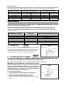
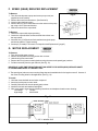
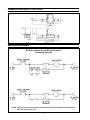
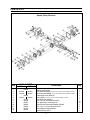
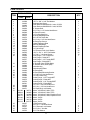
M-Series
Vacuum Pump
OWNER’S MANUAL
Dometic Corporation
13128 State Rt 226, P.O. Box 38
Big Prairie, Ohio 44611-0038 USA
SeaLand Product Hotline 1-800-321-9886
(8:00 a.m. - 5:00 p.m. ET)
1
TABLE OF CONTENTS
Safety Instructions ............................................ 2
Models .............................................................. 2
Installation Instructions...................................... 2
Maintenance ..................................................... 3
Troubleshooting ................................................. 7
Wiring Diagrams ............................................... 8
Dimensional Specifications ................................ 8
Parts List ................................................... 9 - 11
Manufacturer’s One-Year Limited Warranty: .... 12
SAFETY INSTRUCTIONS
WARNING: When using this product, always exercise basic safety precautions including the following:
• Read all instructions before use or installation.
• Never connect this product to any electrical circuit other than the specified voltage, and never exceed the
amperage draw specified in “Electrical Wiring” on page 3.
• Never install, use or service any component of this device in an atmosphere with potentially flammable or
explosive vapors unless specified for explosion-proof atmospheres.
NOTE: EXPLOSION-PROOF COMPONENTS MUST BE WIRED TO NEC CLASS 1, DIV. 2, GROUP D
REQUIREMENTS.
MODELS
PART NUMBER
VOLTAGE
HORSEPOWER
501200
502400
503200
511500
12VDC
24VDC
32VDC
115/230VAC
1/2
1/2
1/2
1/2
Also available with optional 3/4 horsepower, explosion-proof and 50 cycle motors.
INSTALLATION INSTRUCTIONS
Preparation
1. Note: Motor is shipped separately in its own carton. Remove motor from carton.
2. Verify that motor shaft key, mounting bolts, and lock washers are included.
3. Be sure motor shaft is clean and free of dirt. Remove any “burrs” that may be present in the keyway of motor
shaft.
4. Remove pump from shipping carton.
5. Do not clean grease from the inside of the input shaft of the gear reducer.
6. Insert key in motor shaft keyway. Align motor shaft key with keyway in gear reducer input shaft.
7. Insert motor shaft until motor fits against flange on gear reducer. Align four (4) clearance holes in the flange
with the four (4) threaded holes in the motor.
8. Secure the motor to the gear reducer using the four (4) 3/8"-16 x 1" hex head screws and lock washers
supplied with the pump.
Mounting the Pump
1. Remove shipping platform from bottom of pump.
2. Set pump in position with inlet and outlet pointing in direction of flow.
3. Secure pump to mounting surface using 1/4" (6mm) diameter or larger fasteners.
NOTE: Due to the unbalanced weight of the pump, it is important that adequate fastener size be used
to secure the pump.
2
Electrical Wiring
It is imperative that adequate wire size and proper over-current protection (fuse or circuit breaker) sizes are used.
The following chart can be used as a guideline. Refer to chart on page 10 for solenoid/relay information.
PUMP VOLTAGE
12 VDC
24 VDC
32 VDC
115 VAC (1 phase)
230 VAC (1 phase)
BREAKER/FUSE SIZE
PUMP MOTOR WIRE SIZE
1/2 HP
3/4 HP
1/2 HP
3/4 HP
6 to 8 ga.
8 to 10 ga.
10 to 12 ga.
12 to 14 ga.
14 to 16 ga.
3 to 4 ga.
6 to 8 ga.
8 to 10 ga.
10 to 12 ga.
12 to 14 ga.
50 amp
25 amp
20 amp
10 amp
5 amp
75 amp
40 amp
30 amp
15 amp
8 amp
MAINTENANCE
ELECTRICAL CAUTION: DISCONNECT POWER SUPPLY TO PUMP BEFORE SERVICING UNIT. FOLLOW
PROPER LOCK-OUT/TAG-OUT PROCEDURES.
Maintenance intervals and normal parts replacement vary widely depending on numerous factors such as
frequency of system use and quality of flush water, etc. The chart below is intended strictly as a general
guideline. Owner discretion and consideration of actual usage must be the first basis for determining proper
maintenance levels.
Maintenance Procedure
Change Oil
Inspect Diaphragm
Inspect Rod Bushing
Inspect Eccentric Pin
Duckbill Valve Replacement
Speed Reducer Replacement
Motor Replacement
Procedure
Approximate Maintenance Level
A
B
C
D
E
F
G
See instructions
Every two years
Every two years
Every two years
Every two years
If needed
If needed
A. CHANGE OIL
Fig. 1
The gear reducer oil should be changed after first 50 hours, thereafter
every 200 hours. Drain and fill with 90W oil or equivalent to bottom of
oil level inspection hole (opposite of output shaft). Grease the rod
bushing every 200 hours. (See item 9 on Pump Parts List)
B. DIAPHRAGM REPLACEMENT
CAUTION: KEEP HANDS AND ALL OTHER EXTREMITIES AWAY FROM ROD AND DIAPHRAGM. FLUSH
THE PUMP WITH CLEAN WATER AND DISINFECTANT BEFORE SERVICING.
When replacing a diaphragm, be sure to follow maintenance instructions B-D.
IMPORTANT: Incorrect alignments and clearances may cause premature diaphragm failure. It is important to insure that proper
alignment is achieved between the eccentric pin and the diaphragm rod. Make sure that clearances are correct between the
diaphragm rod and the eccentric (Fig. 6) and also between the
eccentric and the gear reducer hub (Fig. 7).
To Remove the Diaphragm:
1. Remove pump cover (not used in SaniService applications).
2. Jog motor until rod is at bottom dead center position.
NOTE: See manual rotation method on page 4.
3. Close the maintenance valves (if installed) in the inlet and outlet
piping.
3
Fig. 2
4. Disconnect electrical source to motor, following lock-out/tag-out procedure.
5. Remove the six (6) 5/16" fasteners around the circumference of the pump top.
6. Carefully remove the pump top from the pump body.
7. Turn the pump top upside down to expose the diaphragm and rod bolt. (See Fig. 3)
8. Remove the rod bolt.
9. Pull the diaphragm away from the rod.
10. Clean the old silicone adhesive from the top and bottom diaphragm plate and bottom of the rod.
11. Clean the old grease (if any) from the diaphragm sealing groove in the pump body.
To Install the Diaphragm:
1. Apply bead of silicone adhesive around the rod bolt hole on both sides of the diaphragm and let cure until the
silicone skins over.
2. Assemble the diaphragm, upper and lower plates to the rod.
3. Apply silicone grease to the
diaphragm sealing groove in the
Fig. 3
Fig. 4
pump body.
4. Carefully install the pump top and
diaphragm into the pump body.
Make certain the diaphragm is
properly seated in the groove in
the pump body.
5. Tighten the six (6) 5/16"
mounting bolts in a criss-cross
pattern as shown. (See Fig. 4)
Manual Rotation Method:
1. Remove motor from speed (gear) reducer.
2. Wedge a large flat-bladed screwdriver or pry bar into hollow input
shaft keyway of speed reducer and rotate until rod is at bottom
dead center. (See Fig. 5)
Fig. 5
C. ROD BUSHING INSPECTION AND REPLACEMENT
NOTE: The rod and bearing must be replaced as an assembly
because the bearing is pressed into the rod using special
equipment.
To Inspect:
1. Follow steps 1 through 11 in “To Remove the Diaphragm” on
page 3.
2. Remove the hex nuts from the eccentric pin and slide off the old
rod.
3. Inspect the bushing in the rod for wear by measuring the bushing
diameter. If worn beyond the service limits, replace the rod and
bushing.
New: 0.625" [15.88mm]
Service Limit: 0.630” [16mm]
To Install:
1. Lubricate the bushing and eccentric pin with anti-seize compound.
2. Slide rod onto the eccentric pin. (See Fig. 6)
4
Fig. 6
3. Install and adjust first hex nut for proper bushing clearance of 0.020" [.50mm].
4. Hold adjustment nut from turning and install and tighten the lock nut.
5. Recheck bushing clearance.
IMPORTANT: INADEQUATE CLEARANCE OR LOOSE LOCK NUT WILL CAUSE THE ECCENTRIC TO BIND,
RESULTING IN PUMP STALLING AND PREMATURE BUSHING WEAR.
6. Follow steps 1 through 5 in “To Install the Diaphragm” on page 4.
D. ECCENTRIC PIN INSPECTION AND REPLACEMENT
To Inspect:
1. Follow steps 1 and 2 in the rod bushing inspection and replacement
section.
2. Inspect the eccentric pin diameter for wear. If worn beyond the service
limit replace the eccentric.
New: 0.6248" [15.87mm]
Service Limit: 0.622" [15.80mm]
3. Remove the eccentric by loosening the pinch bolt and jamming a flatblade screwdriver into the pinch bolt slot.
Fig. 7
To Install:
1. Slide the new eccentric onto the output shaft until the output shaft is
flush with the end of the eccentric. Make certain the key is in the keyway
and flush with the end of the eccentric. (See Fig. 7)
2. Slide eccentric in or out to adjust eccentric to speed (gear) reducer
clearance of 0.075" [1.9mm], tighten pinch bolt and check clearance.
3. Follow step 3 (To Inspect) and steps 1 through 6 (To Install) in Rod
Bushing Inspection and Replacement section. (See Fig. 7)
IMPORTANT: IF OUTPUT SHAFT IS NOT FLUSH WITH ECCENTRIC AFTER CLEARANCE, ADJUSTMENT
WILL BE NECESSARY. LOOSEN THE OUTPUT SHAFT SET SCREWS AND SLIDE THE OUTPUT SHAFT IN
OR OUT ACCORDINGLY.
E. DUCKBILL VALVE INSPECTION AND REPLACEMENT
To Inspect:
1. Flush the pump with fresh water and disinfectant.
2. Close the maintenance valves (if installed) in the inlet and outlet piping.
3. Turn off/disconnect electrical source to the pump motor.
4. Disassemble the inlet/outlet flanges, elbows, and valve housings. (See Fig. 8)
5. Remove the four (4) duckbill valves. Replace all valves if any appear to be: swollen, out of shape, torn, scuffed,
slit or show any other sign of wear.
CAUTION: ORDER VALVES MADE OF EPDM (PART NUMBER: 348702) FOR ALL SEWAGE APPLICATIONS.
ORDER VALVES MADE OF NITRILE (PART NUMBER: 342684) FOR OIL-CONTAMINATED WATER
APPLICATIONS.
Fig. 8
To Install:
1. Insert the two inlet valves pointing toward the pump
body. (See Fig. 8)
2. Insert the two (2) outlet valves pointing away from
the pump body. (See Fig. 8)
5
F. SPEED (GEAR) REDUCER REPLACEMENT
To Remove:
1. Turn off electrical power to pump and remove pump cover (not
supplied on some models).
2. Remove the motor from the reducer. (See Section G)
3. Loosen output shaft set screws.
4. Remove the four (4) 3/8" bolts that secure the reducer to the pump
top using a 9/16" socket and ratchet.
5. Slide the reducer off the output shaft.
Fig. 9
To Replace:
1. Grease the output shaft, keyway and key.
2. Loosen the output shaft set screws and slide the reducer onto
the output shaft.
3. Insert the four (4) 3/8" bolts and lock washers through the pump
and into the reducer. Tighten securely.
4. See step 2 (To Install) in “Eccentric Pin Inspection and Replacement” (page 5).
G. MOTOR REPLACEMENT
To Remove:
1. Turn off electrical power to pump.
2. Remove access plate from wiring junction box on motor.
3. Unhook wiring from motor leads.
4. Remove the four (4) motor mounting bolts securing the motor to the speed (gear) reducer.
5. Pull the motor away from the gear reducer. (See Fig. 10)
IMPORTANT: OVER TIME THE MOTOR SHAFT MAY SEIZE TO THE SPEED (GEAR) REDUCER SHAFT.
IF THIS HAPPENS REFER TO THE NEXT STEP.
6. The speed (gear) reducer motor mounting flange has two threaded holes for forcing the motor off. Use two of
the motor mounting bolts for this application. (See Fig. 10)
To Install:
1. Lubricate motor shaft with an anti-seize compound.
2. Insert key into keyway on motor shaft.
3. Carefully slide the motor into the speed (gear) reducer.
4. Install the four bolts and washers and tighten.
5. Wire motor leads to input wires by following instructions on data plate riveted to motor housing.
Low voltage
=
115VAC
High voltage
=
220/230VAC
Fig. 10
6
TROUBLESHOOTING
WARNING
Before attempting to open or service the pump:
1. If possible, flush pump with clean water and disinfectant.
2. Allow motor to cool if overheated.
3. Disconnect power supply to pump before servicing unit.
Follow proper lock-out/tag-out procedures.
Problem
1. Pump fails to prime.
2. Pump stops or has
reduced flow.
3. Excessive current draw
requires too much
power.
Possible Cause
Service instructions
a. Air leak(s) in suction (inlet) line.
a. Correct leak.
b. Suction (inlet) line collapsed.
b. Replace suction line.
c. Suction (inlet) or discharge (outlet)
check valves clogged or worn out.
c. Clean or replace valves (4 required).
d. Torn or broken diaphragm.
d. Replace diaphragm.
e. Suction line clogged.
e. Clean suction line.
f. Diaphragm or flange bolts loose.
f. Tighten bolts.
a. Air in suction line.
a. Correct leak.
b. Suction line collapsed.
b. Replace suction line.
c. Torn or broken diaphragm.
c. Replace diaphragm.
d. Clogged suction or discharge line.
d. Clean suction or discharge line.
e. Suction lift or discharge lift (head)
too high.
e. Check installation and correct as
required.
f. Suction or discharge valves in pump
clogged or defective.
f. Clean or replace valves (4 required).
a. Liquid solution too thick.
a. Dilute if possible.
b. Discharge valves in pump clogged.
b. Clean or replace valves (2 required).
c. Excessive suction or discharge lifts
(head).
c. Check installation and correct as
required.
a. Pump, gear reducer or motor loose.
a. Tighten bolts.
b. Gear reducer low on oil.
b. Check oil level.
4. Excessive noise.
7
DIMENSIONALSPECIFICATIONS
WIRING DIAGRAMS
M-Series Vacuum Pump Wiring Schematic
(VacuFlush System)
NOTE: Vacuum tank pressure switches are wired in parallel for multiple toilet installations.
Wire to B connections only.
8
PARTS LIST
Speed (Gear) Reducer
Item
PART NUMBER
*30:1
*20:1
1
2
3
4
5
6
7
8
9
10
11
12
13
310537
310538
342812
342813
342814
342815
342816
342817
342818
341792
342820
342821
342822
342823
341797
340704
Description
Seal and Gasket Kit
Bearing and Race Kit
Input Shaft 920 MDSN *(SPECIFY RATIO, SERIAL/MODEL NUMBERS TO ORDER)
Worm Gear 920 MDSN *(SPECIFY RATIO, SERIAL/MODEL NUMBERS TO ORDER)
Output Shaft Cover (800519)
Output Shaft *(SPECIFY RATIO, SERIAL/MODEL NUMBERS TO ORDER)
Input Shaft Cap (800261)
5/16"-18 x 7/8" Hex Head Screw-SS
5/16" Split Ring Lock Washer SS
Gear Reducer Housing 920 MDSN (790509)
5/16"-18 x 1-1/4" Hex Head Screw SS
Motor Adapter Flange (800254)
Retaining Ring (10141)
9
Qty
1
1
1
1
1
1
1
12
16
1
4
1
1
PARTS LIST
M-Series Vacuum Pump
Parts Below Not Shown
1/2HP
3/4HP
12VDC SOLENOID
24VDC SOLENOID
32VDC SOLENOID
115VAC RELAY 50/60 HZ
220VAC RELAY 50/60 HZ
345831
346900
346530
341431
342478
345831
346900
346530
342479
342478
10
PARTS LIST
ITEM
1
2
3
4
5
6
7
8
9
10
11
12
13
14
15
16
17
18
19
20
21
22
23
24
25
26
27
28
29
30
31
32
33
34
35
36
PART NUMBER
1/2HP
DESCRIPTION
3/4HP
342469
341598
342422
342466
342770
342454
340689
640286
340720
342413
342472
342759
342404
342405
342419
342406
346604
346615
346795
340687
342459
342675
342757
640321
348702
342684
342456
342449
342402
342403
342467
342688
342462
342675
342756
640321
342468
340688
342471
341188
342771
340918
342465
341765
342699
342772
342773
341146
342775
341127
342776
341118
342777
340707
347773
342761
342760
342762
3/8"-16 x 1/2" Hex Head Screw
.875" x .406" x .042" Flat Washer
Stainless Steel Cover
Gear Reducer 920MDSN 30:1 ratio, 15 GPM
Gear Reducer 920MDSN 20:1 ratio, 20 GPM
5" Output Shaft
5/16"-18 x 1-1/4" Socket Head Screw
M Pump Eccentric
1/4" Output Shaft Key
M Pump Diaphragm Rod
5/8"-18 Thin Series Nut
5/16"-18 x 1-3/4" Hex Head Screw
M Pump Top Closure
Upper Diaphragm Plate
M Pump Diaphragm
Bottom Diaphragm Plate
1/4"-20 Hex Nut
1/4" External Tooth Lock Washer
.625" x .281" x .050" Flat Washer
1/4"-20 x 1" Hex Head Screw
Inlet Flange, 1-1/2" Female NPT
Inlet Flange, 2" Male NPT
Inlet Flange, 1-1/2" Female BSPT
Inlet Flange, 2" Male BSPT
2" Duckbill Valve, EPDM (Black)
2" Duckbill Valve, Nitrile (Red)
Valve Housing
Valve Housing Elbow
M Pump Body
M Pump Base Mounting Bracket
1/4"-20 x 3/4" Hex Head Screw
1/4" NPT Brass Plug
Outlet Flange, 1-1/2" Female NPT
Outlet Flange, 2" Male NPT
Outlet Flange, 1-1/2" Female BSPT
Outlet Flange, 2" Male BSPT
1/2"-13 x 1-1/4" Hex Head Screw
3/8"-16 x 1-1/2" Hex Head Screw
3/8" Split Ring Lock Washer
Motor, 115/230VAC, 60Hz, TEFC
Motor, 115/230VAC, 50Hz, TEFC
Motor, 115/230VAC, 60Hz, Explosion-Proof
Motor, 115/230VAC, 50Hz, Explosion-Proof
Motor, 12VDC
Motor, 24VDC
Motor, 32VDC
1PSI Pressure Vent
3/8"-16 x 1" Hex Head Screw
5/16" External Lock Washer
5/16"-18 x 1" Hex Nut
5/16" Flat Washer
11
QTY
4
4
1
1
1
1
1
1
1
2
6
1
1
1
1
22
22
22
16
1
4
2
1
1
4
1
1
1
4
8
1
1
4
6
6
6
MANUFACTURER’S ONE-YEAR LIMITED WARRANTY
SeaLand warrants to the original purchaser only, that this product, if used for personal, family or household purposes, is
free from defects in material and workmanship for a period of one year from the date of purchase.
If this SeaLand product is placed in commercial or business use, it will be warranted, to the original purchaser only, to be
free of defects in material and workmanship for a period of ninety (90) days from the date of purchase.
SeaLand reserves the right to replace or repair any part of this product that proves, upon inspection by SeaLand, to be
defective in material or workmanship. All labor and transportation costs or charges incidental to warranty service are to be
borne by the purchaser-user.
EXCLUSIONS
IN NO EVENT SHALL SEALAND BE LIABLE FOR INCIDENTAL OR CONSEQUENTIAL DAMAGES, FOR DAMAGES
RESULTING FROM IMPROPER INSTALLATION, OR FOR DAMAGES CAUSED BY NEGLECT, ABUSE, ALTERATION OR
USE OF UNAUTHORIZED COMPONENTS. ALL IMPLIED WARRANTIES, INCLUDING ANY IMPLIED WARRANTY OF
MERCHANTABILITY OR FITNESS FOR ANY PARTICULAR PURPOSE, ARE LIMITED TO A PERIOD OF ONE YEAR FROM
DATE OF PURCHASE.
IMPLIED WARRANTIES
No person is authorized to change, add to, or create any warranty or obligation other than that set forth herein.
Implied warranties, including those of merchantability and fitness for a particular purpose, are limited to one (1) year from
the date of purchase for products used for personal, family or household purposes, and ninety (90) days from the date of
purchase for products placed in commercial or business use.
OTHER RIGHTS
Some states do not allow limitations on the duration of an implied warranty and some states do not allow exclusions or
limitations regarding incidental or consequential damages; so, the above limitations may not apply to you. This warranty
gives you specific legal rights and you may have other rights which may vary form state to state.
To obtain warranty service, first contact your local dealer from whom you purchased this product.
The first choice in marine and RV sanitation.
Dometic Corporation
13128 State Rt 226, PO Box 38, Big Prairie, OH 44611-0038 USA
SeaLand Customer Service
1-800-321-9886
330-496-3211 (8:00 a.m.-5:00 p.m. ET)
Fax: 330-496-3097
www.sealandtechnology.com
® Registered; ™ Trademark of Dometic Corporation.
© 2002 Dometic Corporation
342695 2/02
12