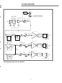
1
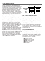
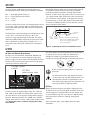
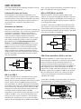
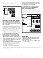
LD-2 Line Driver OPERATING INSTRUCTIONS OPERATING INSTRUCTIONS Superior engineering for the art and science of sound. Keep these important operating instructions CONTENTS Safety Summary The LD-2 Line Driver: Introduction Audio Input AC Power Left And Right Channel Funtions Example Configurations Specifications LD-2 Signal Flow Diagram Front and Rear Panel Detail, Physical Dimensions Notes Contact Information 3 4 4 5 5 6 8 9 10 11 12 SYMBOLS USED THESE SYMBOLS INDICATE IMPORTANT SAFETY OR OPERATING FEATURES IN THIS BOOKLET AND ON THE CHASSIS. ! Dangerous voltages: Important operating risk of electric shock instructions Pour indiquer les risques résultant Pour indequer important de tensions dangereuses instructions Zu die gefahren von gefährliche spanning zeigen Para indicar azares provengo de peligroso voltajes Frame or chassis Protective earth ground Masse, châssis Terre de protection Zu wichtige betriebsanweisung und unterhaltsanweisung zeigen Rahmen oder chassis Die schutzerde Para indicar importante funcionar y mantenimiento instrucciones Armadura o chassis Tierra proteccionista DECLARATION OF CONFORMITY ACCORDING TO ISO/IEC GUIDE AND EN 45014 E NVIRONMENTAL S PECIFICATIONS FOR M EYER S OUND E LECTRONICS P RODUCTS : Operating Temperature 0° to + 45° Nonoperating Temperature <-40°C or > +75°C Humidity to 95% at 35°C Operating Altitude to 4600 m (15,000 ft) Declares that the product: Nonoperating Altitude to 6300 m (25,000 ft) Shock 30g 11 msec half-sine on each of 6 sides Vibration 10Hz to 55Hz (0.010m Conforms to the following Product Specifications peak-to-peak excursion) Safety: EN60065: 1994 1 EMC: EN55103-1 emmission Made by Meyer Sound Laboratories EN55103-2 immunity2 3K59 COMMERCIAL Berkeley, California USA The Manufacturer: MEYER SOUND LABORATORIES, INC. 2832 San Pablo Avenue Berkeley, California 94702-2204, USA LD-2 AUDIO SYSTEM This device complies with the requirements of the Low Voltage Directive 73 / 23 / EEC and the EMC Directive 89 / 336 / EEC. This device also complies with EN 55103-1 & -2. Operation is subject to the following two conditions: (1) this device may not cause harmful interference, and (2) this device must accept any interference received, including interference that may cause undesired operation. 2 European Office: Meyer Sound Lab. GmbH Carl Zeiss Strasse 13 56751 Polch, Germany N757 LD-2 Office of Quality Manager Berkeley, California USA August 31, 2000 ! ENGLISH • To reduce the risk of electric shock, disconnect the unit from the AC mains before installing audio cable. Reconnect the power cord only after making all signal connections. • Connect the unit to a two-pole, three wire grounding mains receptacle. The receptacle must be connected to a fuse or circuit breaker. Connection to any other type of receptacle poses a shock hazard and may violate local electrical codes. • Do not allow water or any foreign object to get inside the unit. Do not put objects containing liquid on, or near, the unit. • To reduce the risk of overheating the unit, avoid exposing it to direct sunlight. Do not install the unit near heat-emitting appliances, such as a room heater or stove. • This unit contains potentially hazardous voltages. Do not attempt to disassemble the unit. The unit contains no user-serviceable parts. Repairs should be performed only by factory-trained service personnel. FRANÇAIS • Pour réduire le risque d’électrocution, débrancher la prise principale de appareil, avant d’installer le câble d’interface allant à l’audio. Ne rebrancher le bloc d’alimentation qu’après avoir effectué toutes les connections. • Branchez appareil dans une prise de courant à 3 dérivations (deux pôles et la terre). Cette prise doit être munie d’une protection adéquate (fusible ou coupe-circuit). Le branchement dans tout autre genre de prise pourrait entraîner un risque d’électrocution et peut constituer une infraction à la réglementation locale concernant les installations électriques. • Ne pas laisser de l’eau ou tout objet SAFETY SUMMARY pénétrer dans appareil. Ne pas placer de r´cipients contenant un liquide sur cet appareil, ni à proximité de celuici. • Pour éviter une surchauffe de appareil, conserver-la à l’abri du soleil. Ne pas installer à proximité d’appareils dégageant de la chaleur tels que radiateurs ou appareils de chauffage. • Ce appareil contient des circuits haute tension présentant un danger. Ne jamais essayer de le démonter. Il n’y a aucun composant qui puisse être réparé par l’utilisateur. Toutes les réparations doivent être effectuées par du personnel qualifié et agréé par le constructeur. DEUTSCH • Um die Gefahr eines elektrischen Schlages auf ein Minimum zu reduzieren, den Gerät vom Stromnetz trennen, bevor ggf. ein AudioSchnittstellensignalkabel angeschlossen wird. Das Netzkabel erst nach Herstellung aller Signalverbindungen wieder einstecken. • Der Gerät an eine geerdete zweipolige Dreiphasen-Netzsteckdose anschließen. Die Steckdose muß mit einem geeigneten Abzweigschutz (Sicherung oder Leistungsschalter) verbunden sein. Der Anschluß der unterbrechungsfreien Stromversorgung an einen anderen Steckdosentyp kann zu Stromschlägen führen und gegen die örtlichen Vorschriften verstoßen. • Darauf achten, daß weder Wasser noch Fremdkörper in das Innere den Gerät eindringen. Keine Objekte, die Flüssigkeit enthalten, auf oder neben die unterbrechungsfreie Stromversorgung stellen. • Um ein Überhitzen dem Gerät zu verhindern, das Gerät vor direkter Sonneneinstrahlung fernhalten und 3 nicht in der Nähe von wärmeabstrahlenden Haushaltsgeräten (z.B. Heizgerät oder Herd) aufstellen. • Im Inneren diesem Gerät herr-schen potentiell gefährliche Spannungen. Nicht versuchen, das Gerät zu öffnen. Es enthält keine vom Benutzer reparierbaren Teile. Reparaturen dürfen nur von ausgebildetem Kundenienstpersonal durchgeführt werden. ESPAÑOL • Para reducir el riesgo de descarga eléctrica, desconecte de la red el aparato antes de instalar el cable de señalización de interfaz de la segnale. Vuelva a conectar el conductor flexible de alimentación solamente una vez efectuadas todas las interconexiones de señalizatción. • Conecte el aparato a un tomacorriente bipolar y trifilar con neutro de puesta a tierra. El tomacorriente debe estar conectado a la protección de derivación apropiada (ya sea un fusible o un disyuntor). La conexión a cualquier otro tipo de tomacorriente puede constituir peligro de descarga eléctrica y violar los códigos eléctricos locales. • No deje que en el aparato entre agua ni ningún objeto extraño. No ponga objetos con líquidos encima de la unidad ni cerca de ella. • Para reducir el riesgo de sobrecalentamiento, no exponga la unidad a los rayos directos del sol ni la instale cerca de artefactos que emiten calor, como estufas o cocinas. • Este aparato contiene niveles de voltaje peligrosos en potencia. No intente desarmar la unidad, pues no contiene piezas que puedan ser repardas por el usuario. Las reparaciones deben efectuarse únicamente por parte del personal de mantenimiento capacitado en la fábrica. THE LD-2 LINE DRIVER:INTRODUCTION Thank you for purchasing the LD-2 Line Driver, one of the two line-level distribution systems offered by Meyer Sound for integrating and optimizing our self-powered loudspeakers. The LD-2 allows system designers and operators to configure and control Meyer Sound self-powered full range, mid-hi, mid-bass, downfill, and subwoofer loudspeakers and any combination of these devices that may be required for real-world sound reinforcement or playback applications. The LD-2 provides the same basic functions as those provided by the LD-1A, but in a more compact package for those sound system applications requiring fewer auxiliary or supplemental loudspeakers. Filter Switch In Filter Switch Out Mid-Bass or AUX Output Sub Output Figure 1 Mid-Bass or AUX and Sub Crossover The LD-2 provides two discrete distribution channels (Left and Right) and each of these is equipped with a master gain control, a master mute switch, and LED indicators to show the presence of input signal, clipping and muting status. The gain and mute controls on each input affect their associated output channels. Additionally, each of the six output channels is equipped with an individual gain control, mute switch and application-specific switched filters. Each output may be utilized as a full-frequency distributed output with gain and muting control or may be configured as Mid-Hi, Mid-Bass, and Sub (woofer) outputs, with appropriate filters. The Mid-Hi output is equipped with a 160Hz Low Cut filter for applications utilizing Meyer Sound Mid-Bass loudspeakers (DS2P or DS-4P). This output is also equipped with a switched Array EQ filter to minimize the increased low-mid frequency output resulting from combined adjacent loudspeakers such as horizontal arrays of MSL-4 loudspeakers. The Mid-Bass and Sub Crossover switch provides filters to the second and third outputs to facilitate employment of Meyer Sound mid-bass loudspeakers (DS-2P or DS-4P) and Meyer Sound subwoofers (650-P or PSW-2), or both (See Figure 1). In applications where mid-hi loudspeakers are used in conjunction with subwoofers (with no supplemental mid-bass loudspeakers), the Mid-Bass/AUX output channels may be employed to feed auxiliary full range or downfill loudspeakers. The Low Cut filter on this output will further optimize the frequency response of mid-hi/full range cabinets connected to the Mid-Bass/AUX output channel. The LD-2 occupies one rack space and is constructed with a 16-gauge steel chassis and 1/8" aluminum rack ears. This rugged design provides protection from physical wear and tear and immunity from EMI. MEYER SOUND LOUDSPEAKER TYPES The following Meyer Sound self-powered loudspeakers are referenced in this document. Please note that the MSL-4 is normally employed as and considered to be a "full range" loudspeaker. As used in the loudspeaker applications described below (wherein there are supplemental “mid-bass” and/or “subwoofer” loudspeakers) the MSL-4 is referred to more accurately as a "mid-hi" loudspeaker. • • • • • • 4 MSL-4 mid-hi loudspeaker CQ Series full range loudspeaker DS-2P/4P mid-bass loudspeaker DF-4 downfill loudspeaker 650-P subwoofer PSW-2 subwoofer AUDIO INPUT The LD-2 presents a 10Ω balanced input impedance to a three-pin XLR connector wired with the following convention: Case — Earth (AC) ground and chassis Pin 1 — Earth (AC) ground and chassis Pin 2 — Signal Pin 3 — Signal The LD-2 is balanced in and out, and consequently has no hot (+) pin. Pins 2 and 3 carry the input as a differential signal. Use standard audio cables with XLR connectors for balanced signal sources. Most modern balanced audio sources (electronically balanced or transformer output) conform to the wiring convention previously described and interface correctly with the LD-2. However, an audio source may produce noise if it connects pin 1 to a quiet internal audio ground, and is then connected to pin 1 of the LD-2 (chassis/earth). To alleviate this noise, try disconnecting pin 1 (or the cable shield) of the audio source. To connect an unbalanced audio source to the LD-2, use the wiring connections shown below: RCA output jack LD-2 input XLR - 3 + The audio input signal should always be applied between pins 2 and 3. Pin 1 is connected to the chassis which also connects to earth ground through the AC cable. This allows interference (EMI and ESD) coupled to the shield of the audio cable to bleed back to earth ground. Therefore, pin 1 is a noisy ground and audio signals should not be connected to pin 1. 2 Tip is positive terminal Ring is negative terminal ï 1 ï Chassis/Earth terminal Shield Connect shield to - terminal (ring) if the source equipment is floating. Do not connect the shield if the source is grounded. Figure 2 Connecting the LD-2 to an unbalanced source AC POWER AC INLET AND VOLTAGE SELECT SWITCH The LD-2 uses an international standard IEC 320 Mains AC inlet. This convenient rear panel receptacle accepts many power cord types for mains outlets used throughout the world. The LD-2 must have the correct power cord for the AC power in the area in which it will be used. The audio outputs are muted internally during normal power on and off, and in case of sudden loss of AC power or unstable line voltage. This precaution prevents noise transmission, and possible damage, to interconnected devices. Voltage select switch IEC 320 male power inlet Do not use a ground-lifting adapter or cut the AC ground pin. To avoid electrical shock and damage to the unit, use the power cord specified by Meyer Sound or an equivalent that satisfies the requirements of the local safety testing agency. Do not operate the unit if the power cables are frayed or broken. AC FUSE Figure 3 The LD-2’s dual voltage operation The LD-2 operates in two AC voltage ranges: 90 - 125V and 180 - 250V, at 50 or 60Hz. The voltage select switch on the rear panel must be set to the proper voltage before applying AC power. Connecting the LD-2 to a 225VAC source with the voltage select switch in the 90 - 125V position could blow the fuse. Unplug the power cord before changing the voltage select switch! 5 Always disconnect the power cord before changing the fuse. To replace the fuse, insert a flat-blade screwdriver in the fuse cap and gently turn counterclockwise; the fuse springs from its socket. Replace only with a 5 x 20 mm, T 250 mA, 250 V, time-lag fuse that conforms to identical safety agency standards. If the fuse blows again, contact Meyer Sound for repair information. LEFT AND RIGHT CHANNEL FUNCTIONS Each channel is equipped to control a full range main system. Each has a Signal/Mute-Clip LED indicator; mute switch; gain control; Mid-Hi, Mid-Bass or AUX, and Sub output controls; and a male XLR output connector for each output. The Master gain control sets the channel's overall level. The Mute switch mutes the entire channel. The bicolor Signal/Mute-Clip LED indicates input signal presence and level with a variable intensity green color, and clipping or mute with red. switch should be out. NOTE: Meyer Sound’s self-powered subwoofers are equipped with internal active processing that provides carefully derived low and high pass filters. Therefore, these loudspeakers may be fed with full range signals directly from the system source or with lowpass filtered signals from Meyer Sound LD-1A or LD2 processors. We do not recommend feeding these subwoofers with low-pass signals from third-party external crossovers due to the uncertainty of the resulting phase response from these filters. The Mid-Hi, Mid-Bass/Aux and Sub outputs each have a level control and mute switch. The level control modifies the level set by the channel's Master gain control; the mute switch affects the corresponding Mid-Hi, Mid-Bass/Aux, or Sub output only. For example, the Mid-Hi output could be muted without affecting the Sub or Mid-Bass/Aux outputs. Additional functions specific to each output are described in the following sections. The Mid-Bass/Aux and Sub outputs each have a polarity switch (φ and Sub φ, respectively). With the switch out, the polarity is set to 0ø. Pushing the switch in inverts the polarity 180ø with respect to the out position. MID-HI OUTPUT In applications where only the Mid-Hi and Sub output sections are used for the main system, the Mid-Bass/AUX sections on both channels may be used for driving auxiliary systems such as fill loudspeakers. When mid-high or full range cabinets (MSL-4, CQ-1/2) are connected to the Mid-Bass or AUX output as auxiliary systems, a Low Cut filter is provided which rolls off frequencies below 160Hz (-12dB/octave). The Mid-Hi output has two switch-activated, optimized filters. Pushing in the Lo Cut switch activates a high-pass filter (160 Hz, Q = 0.8, -12 dB/octave) that performs a crossover function for the Mid-Hi output. The filter is bypassed with the switch out (Figure 4). This filter compensates for the low frequency rise in the overlap region when MSL-4 and PSW-2 cabinets are arrayed together. Pushing the Array EQ switch in activates a filter (6 dB cut at 220 Hz, 0.6 octave bandwidth) to equalize the low-mid rise produced by three to five horizontally arrayed MSL-4s. The filter is bypassed with the switch out. (Figure 4) No Low Cut NOTE: The Array EQ filter compensates for MSL-4 array characteristics in free-space. We recommend using the Meyer Sound SIM System II Sound Analyzer1 and CP10 Parametric Equalizer2 to measure and correct problems caused by the acoustical environment. Low Cut In It is important to note that the Mid-Hi output produces a fullrange signal when both the Array EQ and Lo-Cut filters are out (bypassed). MID-BASS/AUX AND Array EQ In SUB OUTPUTS The Mid-Bass/Aux & Sub Crossover network, optimized for the DS-2P or DS-4P and 650-P or PSW-2 is composed of a low-pass and an elliptical filter. Pushing the switch in activates the two-way crossover, sending frequencies below 80 Hz to the Sub output and above 80 Hz to the Mid-Bass/Aux output. Array EQ and Low Cut In With the switch out, a full-range signal is sent to both the Mid-Bass/Aux and Sub outputs. When a DS-2P or DS-4P is used alone as a subwoofer, or is not included in the system, the Figure 4 The LD-2’s Mid-Hi Output Filters 1. The Meyer Sound SIM II is a computer-based dual channel FFT analysis system optimized for electroacoustic measurement. 2. The CP-10 is a dual-channel, complimentary phase, precision analog equalizer with five bands of parametric equalization and two bands of shelving filters. 6 EXAMPLE CONFIGURATIONS This section demonstrates the flexibility and utility of the LD2 with four sample applications. larger size does preclude tight-packing configurations with the MSL-4. The 650-P also lacks rigging hardware. LOUDSPEAKER PLACEMENT MSL-4, DS-2P/DS-4P, AND POLARITY The loudspeakers in the following configurations are in a close-proximity coplanar orientation, unless otherwise stated. In general practice, placing adjacent loudspeakers more than 5 feet apart may require setting them to opposite polarities to compensate for the propagation delay between these loudspeakers. MEASUREMENT AND The MSL-4 is driven from the Mid-Hi output with the Lo Cut filter switched in for the purpose of minimizing overlap that would otherwise alter the frequency response when combined with the DS-2P/4P and 650-P. Invert the polarity of the 650-P versus that of the MSL-4 and DS-2P/4P. CORRECTION Mid-Hi MSL-4 LD-2 Input Line Driver Sub Mid-Bass 650-P Figure 6 The LD-2 with an MSL-4, DS-2P/4P, and 650-P PSW-2 FLOWN WITH MSL-4; 650-P ON THE FLOOR Positioning subwoofers in a flown cluster (along with the other loudspeaker components) is preferred by some designers because in doing so the low and mid-hi frequencies are produced and aurally localized (perceptually) to a single or centralized source. The identical dimensions of the PSW-2 and MSL-4 allow them to be easily flown together. The Mid-Hi output drives the MSL-4 with the Lo Cut filter in. The Sub and Mid-Bass outputs drive the 650-Ps and PSW-2s with the MidBass and Sub Crossover switches out, sending a full-range signal to each loudspeaker and providing independently adjustable level control. Figure 5 The LD-2 with an MSL-4 and PSW-2 AND 650-P Adding the DS-2P or a DS-4P to an MSL-4/650-P system enhances LF power and clarity. With the Mid-Bass or AUX and Sub Crossover switches in, the Mid-Bass and Sub outputs are sent signals optimized for the frequency response capabilities of the DS-2P/4P and 650-P. Measurement and correction tools are required to optimize any professional sound system. This is all the more necessary and complicated for applications requiring large numbers of loudspeakers, loudspeakers in complex acoustic spaces (in which there will be multiple interactions between the loudspeakers and the architectural/acoustic surfaces) and/or when multiple loudspeaker positions or zones are required. We recommend using the Meyer SIM System II Sound Analyzer and CP-10 Parametric Equalizers to assist in the process of choosing and configuring loudspeaker positions. SIM-II is perfectly suited to measure propagation delays between subsystems, to set the correct polarity and signal delay, to measure and to equalize the frequency response resulting from the acoustical environment and the interaction between loudspeakers. Contact Meyer Sound for assistance with your application. MSL-4 AND PSW-2 The MSL-4 and PSW-2 form a compatible full-range system. However, due to an overlap in the low frequency range between the two adjacent loudspeakers there will be increased acoustic output over the 65-120Hz frequency range when these loudspeakers are combined. Note that the loudspeakers are in phase in this region. The combined frequency response may be optimized by activating the Lo Cut filter on the MidHi output of the LD-2. Ensure that the polarity switches for the output channels feeding the MSL-4 and PSW-2 loudspeakers are not inverted. In most applications, the ratio of MSL-4's to PSW-2's is 2:1, but the Sub and Mid-Hi gain controls in the LD-2 allow for variations in this ratio while maintaining the spectral balance of the system. The 650-P may be used interchangeably with the PSW-2 but the 650-P's Set the MSL-4 and PSW-2 to the same polarity. The polarity of the 650-P depends on the height and distance of the measurement position from the subwoofers and flown cluster. Figure 7 The LD-2 with an MSL-4, PSW-2, and 650-P 7 MSL-4 AND PSW-2 WITH CQ DOWN-FILL3 The correct polarity for the 650-P subwoofers is dependent on the height and distance of the measurement position relative to the subwoofers and the flown loudspeakers. This example shows the LD-2 used to integrate a system of self-powered loudspeakers for a larger venue. We recommend that the entire system be measured, phasealigned, and equalized using the SIM System II Sound Analyzer and CP-10 Parametric Equalizer. LD-2 Mid-Hi Output Input Set the MSL-4 and 650-P to the same polarity; reverse the polarity of the CQ. The polarity of the 650-P depends on the distance of the measurement position from the subwoofer and flown systems. MSL-4 Mid-Hi Mid-Bass Aux Output Sub Output CQ Down-fills LD-2 Right PSW-2 Subwoofers CP-10 EQ Input Figure 8 The LD-2 with an MSL-4, PSW-2, and CQ downfill MSL-4 FLOWN FOR MAINS, CQ DOWN FILL, AND Mid-Hi Output Mid-Bass/Aux Output Sub Output 650-P Figure 9 shows half of the system using the Left channel; identical connections can be used for the Right channel to create the other half. The MSL-4 and CQ arrays are flown; the 650-Ps are on the floor. Delay MSL-4 Mid-Hi Left Mid-Hi Output CP-10 EQ Mid-Bass Input Mid-Bass/Aux Output The Mid-Hi output drives the MSL-4 flown array. Array EQ switches should be in, to minimize the additional low-mid energy from the combined CQ's and MSL-4's. The Lo Cut filter should be switched out, as there is no significant overlap between the MSL-4s and the 650-P with this physical arrangement. The Left channel's Mid-Bass/Aux output controls the CQ down-fill system. Because the primary section of this array will have greater acoustic output than that of the downfill system, there will be audible and measurable low frequency energy from the primary loudspeakers into the downfill coverage area. To insure that these loudspeakers combine properly in this intersecting downfill coverage area: 650-P Subwoofers Figure 9 The LD-2 with an MSL-4, Mid-Bass loudspeakers (the DS-4P is shown), CQ, and 650-P DIFFERENTIAL INPUTS 1. 0 dBV = 1 Vrms; 0 dBu = 0.775 Vrms; 0 dBm = 1 mWrms 2. Ratio of maximum sinewave to A-weighted noise floor. 3. Level set to unity gain (0 dB). 4. 0 dBV, 1 kHz sinewave input. Gain at +12 dB main channel, +6 dB auxiliary channel. · Invert the polarity to the CQ's in order to align them to the high frequency output of the MSL-4's and to reduce combining in the low frequency range. · Use the Mid-Bass/Aux Lo Cut filter to eliminate the LF rise caused by the overlap in frequency response with the 650-P · Delay the down-fill to compensate for the propagation delay between the down-fill and primary loudspeakers in the intersecting coverage area. · The Mid-Bass and Sub crossover switch should be out. 3. This arrangement will work with any suitable loudspeaker system, e.g. DF-4, UPA-1P/2P, etc. 8 LD-2 SPECIFICATIONS A r c h i t e c t u r e1 Master Left and Right Gain Controls Mid-Hi, Mid-Bass/Aux, Sub Gain Controls Low-cut Filter for Mid-High & Mid-Bass/Aux Output Array EQ Filter for Mid-Hi Output Mute Polarity Audio Inputs Connector Type Impedance Wiring RF Filter Common Mode Rejection Ratio Signal Presence/clip LED LED Threshold LED Full Intensity Audio Outputs A C Po w e r Audio Pe r f o r m a n c e GAIN RANGE GAIN RANGE Physical Notes 1 female XLR per channel Differential balanced input circuit 10 kΩ differential (between pins 2 and 3) Pin 1: chassis/earth ground; Pin 2: signal; Pin 3: signal Common Mode: 425 kHz low-pass; Differential Mode: 142 kHz low-pass > 80 dB (typically 90 dB); measured in the range 50 Hz - 1 kHz (Variable intensity; monitored at the input for each channel) -26 dBV (50 mVrms) pink noise or sinewave -10 dBV (300 mVrms) pink noise or sinewave Type Balanced, cross-coupled simulated transformer topology Impedance 10Ω balanced (between pins 2 and 3) RF Filter Pins 2 and 3 shunted to chassis via 500 pF capacitance CONNECTORS CONNECTORS DRIVE CAPABILITY DRIVE CAPABILITY -12 to +6 dB -12 to +6 dB 160 Hz high-pass, -12 dB/octave, Q = 0.8 6 dB cut at 220 Hz, 0.6 octave bandwidth Mute switches for Master, Mid-Hi, Mid-Bass or AUX, and Sub outputs Toggles for Sub and Mid-Bass/Aux outputs Main 1 female XLR/channel Wiring Pin 1: chassis/earth ground; Pin 2: signal; Pin 3: signal Maximum Voltage 1600 Ω Load: +/-22.5 Vpk (+24 dBV, +26.2 dBu sinewave) No Load: +/-25.0 Vpk (+25 dBV, +27.2 dBu sinewave) Maximum Current +/-70 mApk (10 Vrms into 200 Ω) Cables and Load Drives > 100,000 pF (> 1000 ft cable) without instability or distortion Connector IEC 320 (line, neutral/line, earth) Operating Voltage 90 - 125 VAC / 180 - 250 VAC (selectable with rear panel switch); 50/60 Hz Maximum Power 25 Watts; Fuse: 5 x 20 mm, T 250 mA, 250 V, time-lag Frequency Response Bandwidth Phase Response Dynamic Range2 Noise Floor3 THD + N4 Gain Accuracy Mute Attenuation < +/-0.2 dB 20 Hz - 20 kHz DC to 60 kHz (-3dB) < +/-3o from pure 3 µsec delay (DC - 20 kHz) > 120 dB > -95 dBV A-weighted; > -90 dBV un-weighted < 0.005% (typically 0.002%) < +/-0.15 dB at +6 dB gain; < +/-0.25 dB at 0 dB gain > 80 dB Each Channel -12 to +6 dB Auxiliary Channels Dimensions Height: 1.75” (1 rack space); Width: 16.75”; Depth: 6.96” Weight 13.5 lb (6.1 kg); shipping: 15 lb (6.8 kg) Enclosure/Finish Black 16-gauge steel chassis; 1/8” aluminum rack ears 1. 0 dBV = 1Vrms; 0 dBu = 0.775 Vrms; 0dBm = 1 mWrms 2. Ratio of maximum sinewave to A-weighted noise floor 3. Level set to unity gain (0 dB) 4. 0 dBV, 1 kHz sinewave input. Gain at +12 dB main channel Copyright © 2000 Meyer Sound Laboratories, Inc. All Rights Reserved 9 LD-2 SIGNAL FLOW DIAGRAM LED SIGNAL & CLIP DETECTOR GRN RED MUTE SWITCHES RED Common mode: 425kHz low-pass Normal mode: 142kHz low-pass XLR 80dB CMRR Laser Trimmed 3 Input 10kΩ RF & ESD FILTER 1 Master Mute Switch DIFF AMP fc 2 Master Level Earth and Chassis GND -12 to +6dB Audio GND 10Ω on power supply board High Current Full range Flat Mid-Hi Level Mid-Hi Mute Switch XLR DIFFERENTIAL DRIVER Low-cut ArrayEQ Full range 2 Mid-Hi Output 1 High Current Polarity normal XLR DIFFERENTIAL DRIVER Crossover PWR-ON PWR-OFF MUTE RF BLOCK 3 2 Polarity inverted -12 to +6dB 80Hz Elliptical 3 Earth and Chassis GND Mid-Bass or Aux Mid-Bass or Aux Level Mute Switch Low-cut RF BLOCK -12 to +6dB –6dB at 220Hz; 0.6 octave bandwidth 160Hz Q=0.8 -12dB/oct PWR-ON PWR-OFF MUTE Mid-Bass Output 1 Mid-Bass or Aux & Sub Crossover Earth and Chassis GND High Current Sub Level Full range Sub Mute Switch Polarity normal XLR DIFFERENTIAL DRIVER Crossover -12 to +6dB Polarity inverted 65Hz Q=0.9 -12dB/oct PWR-ON PWR-OFF MUTE RF BLOCK 3 2 Sub Output 1 Earth and Chassis GND Both channels of the LD-2 are identical. 10 FRONT AND REAR PANEL DETAIL, PHYSICAL DIMENSIONS All units in inches 3.45 16.75 19.00 The front of the LD-2, showing rack ears and corresponding space requirements 3.45 16.75 Rear 3.45 6.86 Side 11 CONTACT INFORMATION Meyer Sound Laboratories, Inc. 2832 San Pablo Avenue Berkeley, CA 94702 tel: 510.486.1166 fax: 510.486.8356 e-mail: [email protected] www.meyersound.com 05.088.003.01 Rev A