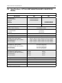
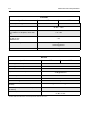
1
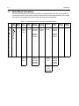
Portable Radios
quality
versatility
versatility
C
Supplement to
Basic Service Manual (Canada Only)
*6881093C57*
Professional Portable Radio Basic Service Manual 68P80906Z54
A, Motorola, Professional Radio - As Dedicated As You Are, HT
Series, MTX Series, and Call Alert are trademarks of Motorola, Inc.
LTR is a registered trademark of E.F. Johnson Company.
© 2000, 2001 Motorola, Inc. All Rights Reserved. Printed In U.S.A.
68P81093C57-B
Professional Radio
quality
As Dedicated As You Are™
HT750•LS
MTX150
MTX450
MTX1500
MTX4500
COMPUTER SOFTWARE COPYRIGHTS
The Motorola products described in this manual may include copyrighted Motorola computer programs
stored in semiconductor memories or other media. Laws in the United States and other countries preserve
for Motorola certain exclusive rights for copyrighted computer programs including, but not limited to, the
exclusive right to copy or reproduce in any form the copyrighted computer program. Accordingly, any copyrighted Motorola computer programs contained in the Motorola products described in this manual may not
be copied, reproduced, modiÞed, reverse-engineered, or distributed in any manner without the express
written permission of Motorola. Furthermore, the purchase of Motorola products shall not be deemed to
grant either directly or by implication, estoppel, or otherwise, any license under the copyrights, patents or
patent applications of Motorola, except for the normal non-exclusive license to use that arises by operation
of law in the sale of a product.
This document supplements the information in the
Basic Service Manual Part Number 68P80906Z54-B.
Supplement Basic Service Manual 68P80906Z54-B contains
VHF information for the following portable radio models:
¥ HT750¥LS
¥ MTX150
¥ MTX450
¥ MTX1500
¥ MTX4500
.
© 2001 by Motorola, Inc.
8000 W. Sunrise Blvd.
Ft. Lauderdale, FL 33322, U.S.A.
All rights reserved. Printed in U.S.A.
i
SAFETY AND GENERAL INFORMATION
IMPORTANT INFORMATION ON SAFE AND EFFICIENT OPERATION
READ THIS INFORMATION BEFORE USING YOUR MOTOROLA TWO-WAY RADIO
The information provided in this document supersedes the general safety information contained in user guides
published prior to October 2000. For information regarding radio use in a hazardous atmosphere refer to the
Factory Mutual (FM) manual supplement included with radio models that offer this capability and/or the
intrinsic safety radio information section of this user manual.
RADIO FREQUENCY (RF) OPERATIONAL CHARACTERISTICS
To transmit (talk) you must push the Push-To-Talk button; to receive (listen) you must release the
Push-To-Talk button. When the radio is transmitting, it generates radio frequency (RF) energy; when it is
receiving, or when it is off, it does not generate RF energy.
PORTABLE RADIO OPERATION AND EME EXPOSURE
Your Motorola radio is designed to comply with the following national and international standards and
guidelines regarding exposure of human beings to radio frequency electromagnetic energy (EME):
•
United States Federal Communications Commission, Code of Federal
Regulations; 47 CFR part 2 sub-part J
•
American National Standards Institute (ANSI) / Institute of Electrical and
Electronic Engineers (IEEE) C95. 1-1992
•
Institute of Electrical and Electronic Engineers (IEEE) C95.1-1999 Edition
•
National Council on Radiation
Protection and Measurements (NCRP) of the United States, Report 86, 1986
•
International Commission on Non-Ionizing Radiation Protection (ICNIRP) 1998
•
Ministry of Health (Canada) Safety Code 6. Limits of Human Exposure to Radio Frequency Electromagnetic Fields in the Frequency Range from 3 kHz to 300 GHz, 1999
•
Australian Communications Authority Radiocommunications (Electromagnetic Radiation - Human Exposure) Standard 1999 (applicable to wireless phones only)
To assure optimal radio performance and make sure human exposure to radio frequency
electromagnetic energy is within the guidelines set forth in the above standards, always adhere to the
following procedures:
Two-way Radio Operation
When using your radio, hold the radio in a vertical position with the microphone one to
two inches (2.5 to 5 centimeters) away from the lips.
Body-worn Operation
To maintain compliance with FCC RF exposure guidelines, if you wear a radio on your body
when transmitting, always place the radio in a Motorola approved clip, holder, holster,
case, or body harness for this product. Use of non-Motorola-approved accessories may exceed FCC RF
exposure guidelines. If you do not use a Motorola approved body-worn accessory and are not using the
radio in the intended use positions along side of the head in the phone mode or in front of the face in
the two-way radio mode, then ensure the antenna and radio is kept the following minimum distances
from the body when transmitting:
MAN WITH RADIO
•
Phone or Two-way radio mode: one inch (2.5 centimeters)
•
Data operation using any data feature with or without an accessory cable: one inch (2.5 centimeters)
ii
Safety and General Information
Antenna Care
Use only the supplied or an approved replacement antenna. Unauthorized antennas, modifications, or
attachments could damage the radio and may violate FCC regulations.
DO NOT hold the antenna when the radio is “IN USE”. Holding the antenna affects call quality and may
cause the radio to operate at a higher power level than needed.
Approved Accessories
For a list of approved Motorola accessories look in the appendix or accessory section of your radio’s User
Guide.
ELECTROMAGNETIC INTERFERENCE/COMPATIBILITY
Note: Nearly every electronic device is susceptible to electromagnetic interference (EMI) if inadequately
shielded, designed or otherwise configured for electromagnetic compatibility.
Facilities
To avoid electromagnetic interference and/or compatibility conflicts, turn off your radio in any facility where
posted notices instruct you to do so. Hospitals or health care facilities may be using equipment that is
sensitive to external RF energy.
Aircraft
When instructed to do so, turn off your radio when on board an aircraft. Any use of a radio must be in
accordance with applicable regulations per airline crew instructions.
Medical Devices
•
Pacemakers
The Health Industry Manufacturers Association recommends that a minimum separation of 6 inches (15
centimeters) be maintained between a handheld wireless radio and a pacemaker.These recommendations are consistent with those of the U.S. Food and Drug Administration.
Persons with pacemakers should:
•
•
ALWAYS keep the radio more than 6 inches (15 centimeters) from their pacemaker when the radio is
turned ON.
•
Not carry the radio in the breast pocket.
•
Use the ear opposite the pacemaker to minimize the potential for interference.
•
Turn the radio OFF immediately if you have any reason to suspect that interference is taking place.
Hearing Aids
Some digital wireless radios may interfere with some hearing aids. In the event of such interference, you
may want to consult your hearing aid manufacturer to discuss alternatives.
•
Other Medical Devices
If you use any other personal medical device, consult the manufacturer of your device to determine if it is
adequately shielded from RF energy. Your physician may be able to assist you in obtaining this information.
Safety and General Information
iii
SAFETY AND GENERAL
Use While Driving
Check the laws and regulations on the use of radios in the area where you drive. Always obey them.
When using your radio while driving, please:
•
Give full attention to driving and to the road.
•
Use hands-free operation, if available.
•
Pull off the road and park before making or answering a call if driving conditions so require.
OPERATIONAL WARNINGS
!
WARNING
FOR VEHICLES WITH AN AIR BAG
Do not place a portable radio in the area over an air bag or in the air bag deployment area. Air
bags inflate with great force. If a portable radio is placed in the air bag deployment area and the
air bag inflates, the radio may be propelled with great force and cause serious injury to
occupants of the vehicle.
POTENTIALLY EXPLOSIVE ATMOSPHERES
Turn off your radio prior to entering any area with a potentially explosive atmosphere, unless it is a radio type
especially qualified for use in such areas as "Intrinsically Safe" (for example, Factory Mutual, CSA, UL, or
CENELEC). Do not remove, install, or charge batteries in such areas. Sparks in a potentially explosive
atmosphere can cause an explosion or fire resulting in bodily injury or even death.
Note: The areas with potentially explosive atmospheres referred to above include fueling areas such as
below decks on boats, fuel or chemical transfer or storage facilities, areas where the air contains
chemicals or particles, such as grain, dust or metal powders, and any other area where you would
normally be advised to turn off your vehicle engine. Areas with potentially explosive atmospheres are
often but not always posted.
BLASTING CAPS AND AREAS
To avoid possible interference with blasting operations, turn off your radio when you are near electrical
blasting caps, in a blasting area, or in areas posted: "Turn off two-way radio.” Obey all signs and instructions.
OPERATIONAL CAUTIONS
!
Caution
ANTENNAS
Do not use any portable radio that has a damaged antenna. If a damaged antenna comes
into contact with your skin, a minor burn can result.
BATTERIES
All batteries can cause property damage and/or bodily injury such as burns if a conductive material such as
jewelry, keys, or beaded chains touch exposed terminals. The conductive material may complete an electrical
circuit (short circuit) and become quite hot. Exercise care in handling any charged battery, particularly when
placing it inside a pocket, purse, or other container with metal objects.
iv
Safety and General Information
This page intentionally left blank
v
Table of Contents
SAFETY AND GENERAL INFORMATION ........................................................................... i
•
RADIO FREQUENCY (RF) OPERATIONAL CHARACTERISTICS .......................... i
•
PORTABLE RADIO OPERATION AND EME EXPOSURE ....................................... i
•
ELECTROMAGNETIC INTERFERENCE/COMPATIBILITY......................................ii
•
SAFETY AND GENERAL ......................................................................................... iii
•
OPERATIONAL WARNINGS.................................................................................... iii
•
OPERATIONAL CAUTIONS ..................................................................................... iii
Chapter 1
1.1
1.2
1.3
Scope of Manual .................................................................................................... 1-1
Warranty and Service Support ............................................................................... 1-1
1.2.1
Warranty Period and Return Instructions ....................................................... 1-1
1.2.2
After Warranty Period .................................................................................. 1-1
1.2.3
Piece Parts Availability ................................................................................ 1-2
1.2.4
Technical Support ....................................................................................... 1-3
Radio Model Information ........................................................................................ 1-4
Chapter 2
2.1
2.2
Maintenance
HT750•LS Radio Exploded Mechanical View and Parts List ................................. 3-1
MTX450 Radio Exploded Mechanical View and Parts List .................................... 3-2
MTX4500 Radio Exploded Mechanical View and Parts List .................................. 3-3
MTX150 Radio Exploded Mechanical View and Parts List .................................... 3-4
MTX1500 Radio Exploded Mechanical View and Parts List .................................. 3-5
Chapter 4
4.1
Intrinsically Safe Radio Information
FMRC Approved Equipment .................................................................................. 2-1
Repair of FMRC Approved Products...................................................................... 2-2
2.2.1
Repair ........................................................................................................ 2-2
2.2.2
Relabeling .................................................................................................. 2-2
2.2.3
Do Not Substitute Options or Accessories ..................................................... 2-2
Chapter 3
3.1
3.2
3.3
3.4
3.5
Introduction
Transceiver Performance Testing
RF Test Mode ........................................................................................................ 4-1
vi
Chapter 5
5.1
5.2
Cloning (Conventional and LTR) ............................................................................5-1
5.1.1
Error Codes (Display Radios Only) ...............................................................5-2
Cloning (Privacy Plus) ............................................................................................5-2
Chapter 6
6.1
6.2
Accessories
HT750•LS/MTX450/MTX4500/MTX150/MTX1500 Accessories ............................7-1
7.1.1
Antennas ....................................................................................................7-1
7.1.2
Carrying Accessories ...................................................................................7-1
7.1.3
Carry Cases ................................................................................................7-1
7.1.4
Chargers ....................................................................................................7-2
7.1.5
Batteries ....................................................................................................7-2
7.1.6
Adaptors .....................................................................................................7-2
7.1.7
Miscellaneous .............................................................................................7-2
7.1.8
Service Aids ................................................................................................7-2
7.1.9
Audio Accessories ......................................................................................7-3
7.1.10 Option Boards (HT750•LS only) ...................................................................7-3
7.1.11 Remote Speaker Microphones......................................................................7-3
7.1.12 Manuals .....................................................................................................7-4
7.1.13 Retrofit Front Cover Kits ..............................................................................7-4
Chapter 8
8.1
8.2
8.3
8.4
Power Up Self-Test
Error Codes - Conventional and LTR Radios .........................................................6-1
Error Codes - Privacy Plus .....................................................................................6-2
Chapter 7
7.1
Radio Tuning, Programming, and Cloning
Model Chart and Test Specifications
UHF 403-470 MHz (HT Series) ..............................................................................8-1
UHF 403-470 MHz (MTX Series) ...........................................................................8-1
VHF 136-174 MHz (MTX Series)............................................................................8-2
Specifications - HT750•LS/MTX450/MTX4500/MTX150/MTX1500 Radios ...........8-3
vii
List of Figures
Figure 3-1
Figure 3-2
Figure 3-3
Figure 3-4
Figure 3-5
Figure 4-1
Figure 4-2
Figure 5-1
HT750•LS Radio Exploded Mechanical View and Parts List...................... 3-3
MTX450 Radio Exploded Mechanical View and Parts List......................... 3-4
MTX4500 Radio Exploded Mechanical View and Parts List....................... 3-5
MTX150 Radio Exploded Mechanical View and Parts List......................... 3-6
MTX1500 Radio Exploded Mechanical View and Parts List....................... 3-7
Radio Side Button Locations ...................................................................... 4-3
Two-Line Display ........................................................................................ 4-3
Radio Side Button Locations ...................................................................... 5-1
List of Tables
Table 1-1
Table 4-1
Table 4-2
Table 6-1
Table 6-2
Radio Model Number (Example: AAH25RDC9GB3AN) ............................... 1-4
Receiver Performance Checks ..................................................................... 4-4
Transmitter Performance Checks ................................................................. 4-5
Power-up Display Codes - (Conventional Radios) ........................................ 6-1
Power-up Display Codes .............................................................................. 6-2
viii
1-1
Chapter 1
Introduction
1.1
Scope of Manual
This manual is intended for use by service technicians familiar with similar types of equipment. It
contains service information required for the equipment described and is current as of the printing
date. Changes which occur after the printing date may be incorporated by a complete Manual revision
or alternatively as additions.
NOTE Before operating or testing these units, please read the Safety Information Section in the
front of this manual.
1.2
Warranty and Service Support
Motorola offers support which includes: full exchange and/or repair of the product during the warranty
period; and service/repair or spare parts support out of warranty. Any “return for exchange” or “return
for repair” to an authorized Motorola Dealer must be accompanied by a Warranty Claim Form.
Warranty Claim Forms are obtained by contacting an Authorized Motorola Dealer. (See section 1.2.4
on page 1-3.)
1.2.1 Warranty Period and Return Instructions
The terms and conditions of warranty are defined fully in the Motorola Dealer or Distributor or Reseller
contract. These conditions may change from time to time, and the following subsections are for
guidance purposes only.
In instances where the product is covered under a “return for replacement” or “return for repair”
warranty, a check of the product should be performed prior to shipping the unit back to Motorola. This
is to ensure that the product has been correctly programmed or has not been subjected to damage
outside the terms of the warranty.
Prior to shipping any radio back to the appropriate Motorola warranty depot, please contact Customer
Resources (Please see page 2 and page 3 in this chapter.). All returns must be accompanied by a
Warranty Claim Form, available from your Customer Resources representative. Products should be
shipped back in the original packaging, or correctly packaged to ensure that no damage occurs in
transit.
1.2.2 After Warranty Period
After the Warranty period, Motorola continues to support its products in two ways:
1. Motorola's Radio Parts and Service Group offers repair service to users and dealers at competitive prices.
2. AAD supplies individual parts and modules that can be purchased by Dealers who are capable of
performing fault analysis and repair.
1-2
Introduction
1.2.3 Piece Parts Availability
Some replacement parts, spare parts, and/or product information can be ordered directly. If a
complete Motorola part number is assigned to the part, and it is not identified as Depot ONLY, it is
available from the Accessories and Aftermarket Division (AAD). If no part number is assigned, the
part is not normally available from Motorola. If the part number is appended with an asterisk, the part
is serviceable by a Motorola Depot only. If a parts list is not included, this generally means that no
user-serviceable parts are available for that kit or assembly.
Parts Order Entry
7:00 A.M. to 7:00 P.M. (Central Standard Time)
Monday through Friday (Chicago, U.S.A.)
To Order Parts:
1-800-422-4210, or 847-538-8023 (Voice)
1-847-538-8198 (Fax)
After hours or weekends:
1-800-925-4357
Motorola Parts
Accessories and Aftermarket Division
(United States and Canada)
Attention: Order Processing
1313 E. Algonquin Road
Schaumburg, IL 60196
Parts Identification
1-847-538-0021 or 1-800-422-4210 (Voice)
1-847-538-8194 (Fax)
Introduction
1-3
1.2.4 Technical Support
Technical support is available to assist the dealer/distributor in resolving any malfunction which may
be encountered. Initial contact should be by telephone to Customer Resources wherever possible.
When contacting Motorola Technical Support, be prepared to provide the product model number
and the unit’s serial number.
For service you can contact the following Depot. Please call and confirm your return prior to sending
the unit to the depot for service.
Motorola Toronto Service Centre
3900 Victoria Park Avenue
North York, Ontario, Canada M2H 3H7
1-800-543-3222
1-416-756-5841
1-888-331-9872 (Fax)
1-4
1.3
Introduction
Radio Model Information
The model number and serial number are located on a label attached to the back of your radio. You
can determine the RF output power, frequency band, protocols, and physical packages. The example
below shows one portable radio model number and its specific characteristics.
Table 1-1: Radio Model Number (Example: AAH25RDC9GB3)
Model
Series
Freq.
Band
Power
Level
Physical
Packages
Channel
Spacing
H
25
R
UHF1
(403-470
MHz)
D
4-5W
C
HT750•LS
MTX450
9
Programmable
H = Portable
AA or LA = Motorola Internal Use
AA
or
LA
Type
of Unit
Protocol
DU
LTR
MTX150
MTX850
MTX950
K
(136 -174
MHz)
H
MTX4500
MTX1500
MTX8250
MTX9250
Feature
Level
Model
Revision
Model
Package
3
HT750•LS
MTX450
A
N
MTX150
MTX850
MTX950
GB
Privacy
Plus
GE
Privacy
Plus
w/Roaming
6
MTX4500
MTX1500
MTX8250
MTX9250
2-1
Chapter 2
Intrinsically Safe Radio Information
2.1
FMRC Approved Equipment
Anyone intending to use a radio in a location where hazardous concentrations of flammable material
exist (hazardous atmosphere) is advised to become familiar with the subject of intrinsic safety and
with the National Electric Code NFPA 70 (National Fire Protection Association) Article 500 (hazardous
[classified] locations).
An Approval Guide, issued by Factory Mutual Research Corporation (FMRC), lists manufacturers and
the products approved by FMRC for use in such locations. FMRC has also issued a voluntary
approval standard for repair service (“Class Number 3605”).
FMRC Approval labels are attached to the radio to identify the unit as being FM Approved for
specified hazardous atmospheres. This label specifies the hazardous Class/Division/Group along
with the part number of the battery that must be used. Depending on the design of the portable unit,
this FM label can be found on the back of the radio housing or the bottom of the radio housing. Their
Approval mark is shown below.
FM
APPROVED
!
WARNING: Do not operate radio communications equipment in a hazardous atmosphere
unless it is a type especially qualified (e.g. FMRC Approved) for such use. An explosion or
fire may result.
WARNING: Do not operate the FMRC Approved Product in a hazardous atmosphere if it has
been physically damaged (e.g. cracked housing). An explosion or fire may result.
WARNING: Do not replace or charge batteries in a hazardous atmosphere. Contact sparking
may occur while installing or removing batteries and cause an explosion or fire.
WARNING: Do not replace or change accessories in a hazardous atmosphere. Contact
sparking may occur while installing or removing accessories and cause an explosion or fire.
WARNING: Do not operate the FMRC Approved Product unit in a hazardous location with the
accessory contacts exposed. Keep the connector cover in place when accessories are not
used.
WARNING: Turn radio off before removing or installing a battery or accessory.
WARNING: Do not disassemble the FMRC Approved Product unit in any way that exposes
the internal electrical circuits of the unit.
Radios must ship from the Motorola manufacturing facility with the hazardous atmosphere capability
and FM Approval labeling. Radios will not be “upgraded” to this capability and labeled in the
field.
A modification changes the unit’s hardware from its original design configuration. Modifications can
only be done by the original product manufacturer at one of its FMRC audited manufacturing
facilities.
2-2
Intrinsically Safe Radio Information
!
WARNING: Failure to use an FMRC Approved Product unit with an FMRC Approved battery
or FMRC Approved accessories specifically approved for that product may result in the dangerously unsafe condition of an unapproved radio combination being used in a hazardous
location.
Unauthorized or incorrect modification of an FMRC Approved Product unit will negate the Approval
rating of the product.
2.2
Repair of FMRC Approved Products
REPAIRS FOR MOTOROLA FMRC APPROVED PRODUCTS ARE THE RESPONSIBILITY OF THE
USER.
You should not repair or relabel any Motorola manufactured communication equipment bearing the
FMRC Approval label (“FMRC Approved Product”) unless you are familiar with the current FMRC
Approval standard for repairs and service (“Class Number 3605”).
You may want to consider using a repair facility that operates under 3605 repair service approval.
!
WARNING: Incorrect repair or relabeling of any FMRC Approved Product unit could
adversely affect the Approval rating of the unit.
WARNING: Use of a radio that is not intrinsically safe in a hazardous atmosphere could
result in serious injury or death.
FMRC’s Approval Standard Class Number 3605 is subject to change at any time without notice to
you, so you may want to obtain a current copy of 3605 from FMRC. Per the December, 1994
publication of 3605, some key definitions and service requirements are as follows:
2.2.1 Repair
A repair constitutes something done internally to the unit that would bring it back to its original
condition Approved by FMRC. A repair should be done in an FMRC Approved facility.
Items not considered as repairs are those in which an action is performed on a unit which does not
require the outer casing of the unit to be opened in a manner which exposes the internal electrical
circuits of the unit. You do not have to be an FMRC Approved Repair Facility to perform these actions.
2.2.2 Relabeling
The repair facility shall have a method by which the replacement of FMRC Approval labels are
controlled to ensure that any relabeling is limited to units that were originally shipped from the
Manufacturer with an FM Approval label in place. FMRC Approval labels shall not be stocked by the
repair facility. An FMRC Approval label shall be ordered from the original manufacturer as needed to
repair a specific unit. Replacement labels may be obtained and applied by the repair facility providing
satisfactory evidence that the unit being relabeled was originally an FMRC Approved unit. Verification
may include, but is not limited to: a unit with a damaged Approval label, a unit with a defective housing
displaying an Approval label, or a customer invoice indicating the serial number of the unit and
purchase of an FMRC Approved model.
2.2.3 Do Not Substitute Options or Accessories
The Motorola communications equipment certified by Factory Mutual is tested as a system and
consists of the FM Approved portable, FM Approved battery, and FM Approved accessories or
options, or both. This Approved portable and battery combination must be strictly observed. There
must be no substitution of items, even if the substitute has been previously Approved with a different
Motorola communications equipment unit. Approved configurations are listed in the FM Approval
guide published by FMRC, or in the product FM Supplement. This FM Supplement is shipped with FM
Intrinsically Safe Radio Information
2-3
Approved radio and battery combination from the manufacturer. The Approval guide, or the Approval
standard Class Number 3605 document for repairs and service, can be ordered directly through
Factory Mutual Research Corporation located in Norwood, Massachusetts.
HT750¥LS Radio Exploded Mechanical View and Parts List
3.1
3-1
HT750¥LS Radio Exploded Mechanical View and Parts List
Item
1
See Accessories Chapter
3680529Z01
3680530Z01
1380525Z01
3380644Z01
3280533Z01
6180527Z01
HHLN4059
HHLN4071
1586059A01
1386058A01
1580666Z03
1580666Z04
2
3
4
5
6
7
8
1
2
9
10
11
3
Motorola
Part Number
4
Item
Description
Antenna
12
Knob, Volume
Knob, Channel Selector
Escutcheon, Top
Escutcheon, Label
Seal, Control Top
Litepipe, Tx
Nameplate, HT750¥LS
Nameplate, HT750¥LS DTMF
Dust Cover, Universal Connector
Escutcheon, Universal Flex
Front Cover, Basic
Front Cover with Keypad (DTMF)
13
14
15
16
17
18
19
20
21
22
23
Motorola
Part Number
Not Field
Replaceable
7580532Z01
1380528Z01
7580620Z03
7580620Z04
0104007J99
4280498Z01
3586057A01
1480577C01
5085962A02
5013920A04
8480549Z01
2113740A41
Description
Item
Escutcheon, FM
24
25
26
27
28
29
30
31
32
33
34
Keypad, Side Control
Bezel, Side Control
Keypad, Blank
Keypad, Full
Keypad Board Assembly
Retainer, Keypad PCB
Felt Speaker
Boot, Microphone
Speaker
Microphone
Flex Speaker-Microphone
Capacitor, 33pF
4280504Z01
0304726J04
See section 8.1
8480475Z02
1480652Z01
7580556Z01
3280534Z01
3280536Z01
3980698Z01
2780518Z01
See Accessories Chapter
HLN9714
35
5
6
7
14
13
8
15
18
20
16
24
28 30
31
32
11
9
10
19
12
33
34
21
35
17
23
22
25
26
27
29
Motorola
Part Number
Description
Retainer, Speaker
Screw
Ctrl/RF Board Assembly
Flex, Keypad/Controller
Insulator, Antenna
Pad, Thermal
Seal, Contact
Gasket, O-Ring
Contact, Ground, Compliant, UHF
Chassis
Battery
Beltclip
3-2
3.2
MTX450 Radio Exploded Mechanical View and Parts List
MTX450 Radio Exploded Mechanical View and Parts List
Item
1
2
3
4
5
6
7
8
9
10
11
1
2
3
Motorola
Part Number
See Accessories Chapter
3680529Z01
3680530Z01
1380525Z01
3380644Z01
3280533Z01
6180527Z01
HHLN4212
1586059A01
1386058A01
1580666Z03
1580666Z04
Item
Description
Antenna
12
Knob, Volume
Knob, Channel Selector
Escutcheon, Top
Escutcheon, Label
Seal, Control Top
Litepipe, Tx
Nameplate, MTX450
Dust Cover, Universal Connector
Escutcheon, Universal Flex
Front Cover, Basic
Front Cover with Keypad (DTMF)
13
14
15
16
17
18
19
20
21
22
23
Motorola
Part Number
Description
Not Field
Replaceable
7580532Z01
1380528Z01
7580620Z03
7580620Z04
Keypad, Side Control
Bezel, Side Control
Keypad, Blank
Keypad, Full
0104007J99
4280498Z01
3586057A01
1480577C01
5085962A02
5013920A04
8480549Z01
2113740A41
Keypad Board Assembly
Retainer, Keypad PCB
Felt Speaker
Boot, Microphone
Speaker
Microphone
Flex Speaker-Microphone
Capacitor, 33pF
Item
Escutcheon, FM
24
25
26
27
28
29
30
31
32
33
34
35
4
5
6
7
14
13
8
15
18
20
16
24
28 30
31
32
11
9
10
19
12
33
34
21
35
17
23
22
25
26
27
29
Motorola
Part Number
4280504Z01
0304726J04
See section 8.1
8480475Z02
1480652Z01
7580556Z01
3280534Z01
3280536Z01
3980698Z01
2780518Z01
See Accessories Chapter
HLN9714
Description
Retainer, Speaker
Screw
Ctrl/RF Board Assembly
Flex, Keypad/Controller
Insulator, Antenna
Pad, Thermal
Seal, Contact
Gasket, O-Ring
Contact, Ground, Compliant, UHF
Chassis
Battery
Beltclip
MTX4500 Radio Exploded Mechanical View and Parts List
3.3
3-3
MTX4500 Radio Exploded Mechanical View and Parts List
Item
1
1
See Accessories Chapter
3280529Z01
3280530Z01
1380525Z01
1380525Z03
3380644Z01
3280533Z01
6180527Z01
HHLN4213
1586059A01
1386058A01
1580666Z05
Non Field
Replaceable
7580532Z01
1380528Z01
2
3
4
5
6
7
8
9
10
11
12
2
3
4
5
13
14
6
Motorola
Part Number
Motorola
Part Number
Item
Description
15
Antenna
Knob, Volume
Knob, Frequency
Escutcheon, Top (16CH)
Escutcheon, Top (Dotted)
Escutcheon, Label
Seal, Control Top
Litepipe, Tx
Nameplate, MTX4500
Dust Cover, Univ Conn
Escutcheon, Univ Flex
Front Cover
7586065A01
7586065A02
758568OZ07
0104010J09
7580540Z01
5104949J05
7580637Z01
4280498Z01
3586057A01
1480577C01
5085962A02
5013920A04
8480549Z01
2113740A41
4280504Z01
1480503Z01
6062884G01
16
17
18
19
20
21
22
23
24
25
26
27
28
29
* Escutcheon, FM
Keypad, Side Control
Bezel, Side Control
Description
Item
Keypad, Basic
Keypad, Full,
Keypad, Full, Privacy Plus
Keypad Board Assembly
Pad Display
LCD Module
Pad, LCD Back
Retainer, Keypad PCB
Felt, Speaker
Boot, Microphone
Speaker
Microphone
Flex Speaker-Microphone
Cap, 33pF
Retainer, Speaker
Boot, Backup Battery
Backup Battery
Motorola
Part Number
30
31
32
0304726J04
Screw
3980667Z01
Contact, Finger
See section 8.1 Ctrl/RF Board Assembly
33
34
35
36
37
38
39
40
8485615Z02
1480652Z01
7580556Z01
3280534Z01
3280536Z02
3980698Z01
2780518Z01
See Accessories Chapter
HLN9714
41
7
14
13
8
15
16
17
18
21
19
23
27
28
31
34 36
37
38
11
9
10
39
40
12
22
41
24
20
26
25
29
30
32
33
35
Description
Flex, Keypad/Controller
Insulator, Antenna
Pad, Thermal
Seal, Contact
Gasket, O-Ring
Contact, Ground (For UHF)
Chassis
Battery
Beltclip
3-4
3.4
MTX150 Radio Exploded Mechanical View and Parts List
MTX150 Radio Exploded Mechanical View and Parts List
Item
1
1
Please refer to
section 7.1.1 on
page 7-1
3680529Z01
3680530Z02
4285611Z01
1380525Z01
1380525Z04
3380644Z01
3280533Z01
HHLN4214
2
3
3a
4
4a
5
6
7
8
2
3
9
10
4
5
Motorola
Part Number
1586059A01
1386058A01
Item
Description
11
Antenna
12
Knob, Volume
Knob, Channel Selector
Stop, Mechanical (4-Channel)
Escutcheon, Top
Escutcheon, Top (4-Channel)
Escutcheon, Label
Seal, Control Top
Litepipe, Tx
Nameplate, MTX150 DTMF
Nameplate, MTX150
Dust Cover, Universal Connector
Escutcheon, Universal Flex
13
14
15
16
17
18
19
20
21
22
2
Motorola
Part Number
1580666Z03
1580666Z04
Not Field
Replaceable
7580532Z01
1380528Z01
7580620Z03
7580620Z04
0104007J99
4280498Z01
3586057A01
1480577C01
5085962A02
5013920A04
8480549Z01
2113740A41
Description
Item
Front Cover, Basic
Front Cover with Keypad (DTMF)
Escutcheon, FM
24
25
26
Keypad, Side Control
Bezel, Side Control
Keypad, Blank
Keypad, Full
Keypad Board Assembly
Retainer, Keypad PCB
Felt Speaker
Boot, Microphone
Speaker
Microphone
Flex, Speaker-Microphone
Capacitor, 33pF
27
28
29
30
31
32
33a
33b
34
4280504Z01
0304726J04
See detailed
service manual
8480475Z02
1480652Z01
7580556Z01
3280534Z01
3280536Z01
3980698Z01
2780518Z01
2780518Z03
See section
7.1.5 on page 72
HLN9714
35
6
7
14
13
8
15
18
20
16
24
28 30
31
32
11
9
10
19
12
33
34
21
35
17
23
22
25
26
27
29
Motorola
Part Number
Description
Retainer, Speaker
Screw
Ctrl/RF Board Assembly
Flex, Keypad/Controller
Insulator, Antenna
Pad, Thermal
Seal, Contact
Gasket, O-Ring
Contact, Ground, Compliant, VHF
Chassis
Chassis
Battery
Beltclip
MTX1500 Radio Exploded Mechanical View and Parts List
3.5
3-5
MTX1500 Radio Exploded Mechanical View and Parts List
Item
1
1
2
3
4
5
6
7
8
9
10
11
2
3
4
12
13
5
Motorola
Part Number
Please refer to
section 7.1.1 on
page 7-1
3680529Z01
3680530Z01
1380525Z01
3380644Z01
3280533Z01
6180527Z01
HHLN4215
1586059A01
1386058A01
1580666Z01
1580666Z02
7580532Z01
Description
Antenna
Knob, Volume
Knob, Channel Selector
Escutcheon, Top
Escutcheon, Label
Seal, Control Top
Litepipe, Tx
Nameplate, MTX1500
Dust Cover, Universal Connector
Escutcheon, Universal Flex
Front Cover with DTMF
Front Cover without DTMF
Escutcheon, FM
Keypad, Side Control
Item
Motorola
Part Number
14
15
16
17
18
19
20
21
22
23
24
25
26
27
28
29
1380528Z01
7580620Z02
0104007J99
7580540Z01
5104949J05
7580637Z01
4280498Z01
3586057A01
1480577C01
5085962A02
5013920A04
8480549Z01
2113740A41
4280504Z01
1480503Z01
6062884G01
Description
Item
Bezel, Side Control
Keypad, Full
Keypad Board Assembly
Pad Display
LCD Module
Pad, LCD Back
Retainer, Keypad PCB
Felt Speaker
Boot, Microphone
Speaker
Microphone
Flex, Speaker-Microphone
Capacitor, 33pF
Retainer, Speaker
Boot, Backup Battery
Backup Battery
30
31
32
0304726J04
3980667Z01
See detailed
manual
8480475Z02
1480652Z01
7580556Z01
3280534Z01
3280536Z01
3980698Z01
2780518Z01
See section
7.1.5 on page 72
HLN9714
33
34
35
36
37
38
39
40
41
6
7
14
13
8
15
16
17
18
21
19
23
27
28
31
34 36
37
38
11
9
10
39
40
12
22
41
24
20
26
25
29
30
32
33
35
Motorola
Part Number
Description
Screw
Contact, Finger
Ctrl/RF Board Assembly
Flex, Keypad/Controller
Insulator, Antenna
Pad, Thermal
Seal, Contact
Gasket, O-Ring
Contact, Ground, Compliant
Chassis
Battery
Beltclip
3-6
4-1
Chapter 4
Transceiver Performance Testing
For the missing sub-sections in this chapter, please refer to Basic Service Manual 68P80906Z54.
4.1
RF Test Mode
When the radio is operating in its normal environment, the radio’s microcontroller controls the RF
channel selection, transmitter key-up, and receiver muting. However, when the unit is on the bench for
testing, alignment, or repair, it is removed from its normal environment and cannot receive commands
from its system. Therefore, the internal microcontroller does not key the transmitter or unmute the
receiver. This prevents the use of a normal tuning procedure. To solve this problem, a special “test
mode” is incorporated into the radio.
Note 1: On UHF, LTR models, the radio must be in either conventional or LTR mode.
Note 2: The test mode procedure that follows assumes that the Customer Programming Software
Front Panel Access screen has both the FPA and RF TEST boxes selected. Select from the
programming screen to enable or disable certain features of the radio RF test mode.
●
●
●
FPA entry not selected blocks all test modes.
FPA entry selected and RF TEST not selected blocks RF test mode.
FPA entry selected and RF TEST selected enables all test modes.
To enter the test mode for a display radio:
1. Turn the radio on.
2. Within ten seconds after the self test is complete, press ‘side button 2’, shown in Figure
4-1, five times in succession.
3. After “CSQ CHXX SP25” appears on the display, the radio is on channel XX (see Note
on following page), carrier squelch mode, 25 kHz channel spacing. Each additional
press of ‘side button 2’ (see Table 4-2) scrolls to the next channel spacing, and a corresponding set of tones are sounded. Refer to Figure 4-2 for test mode information for a
two-line display radio.
4. Press ‘side button 1’ to scroll through the test environments listed in Table 4-1 in Basic
Service Manual 68P80906Z54.
5. Press ‘side button 2’ for 3 seconds to switch the radio to the control head test mode.
‘LCD Test’ appears on the display.
6. Press ‘side button 1’ to turn on all the dots of the first character. Another ‘side button 1’
press turns on all the dots of the next character, continuing until the last character is
reached.
7. Press ‘side button 1’ at the end of the LCD test to activate the ‘Icon Test’. The next ‘side
button 1’ press turns on the first icon.
8. Press ‘side button 1’ at the end of the Icon Test to activate the button test. Pressing any
side button (except ‘side button 1’), or any keypad button during the LCD test or Icon
test immediately activates this test. A good button press is verified by a chirp.
9. Press ‘side button 2’ for 3 seconds in the control head test mode to return the radio to
the RF Test mode.
4-2
Transceiver Performance Testing
10. Turn radio off to exit test mode.
Note:
XX = channel number (01 - 14)
To enter the test mode for a non-display radio:
1. Turn the radio on.
2. Within ten seconds after the self test is complete, press ‘side button 2’ (Figure 4-1) five
times in succession.
3. Press ‘side button 1’ the number of times listed in Table 4-1 to get the number of corresponding beeps.
4. Turn radio off to exit test mode.
5. To access all 14 test modes on a 4-channel radio, the frequency knob and mechanical
stop sleeve must be removed (see paragraph 3-8 exploded view diagram).
Button Test (For models with ”G” in location 10 of model number Example: AAH25RCH6GB6AN)
1. Press the orange button; “3/1” appears which indicates that switch 3 is in the closed condition.
2. Release the orange button; “3/0” appears which indicates that switch 3 is in the open condition.
3. Rotate the mode selector knob; “4/0”through “4/15” appears which indicates that knob 4 is in
mode position 1 through 15.
4. Rotate the volume control; “2/0” through “2/255” appears.
5. Press SB1, view “96/1”; release, view “96/0”.
6. Press SB2, view “97/1”; release, view “97/0”.
7. Press SB3, view “98/1”; release view “98/0”.
8. Press PTT button, view “1/1”; release view “1/0”.
Keypad (For models with ”G” in location 10 of model number Example: AAH25RCH6GB6AN)
1. Press 0, view “48/1”; release, view “48/0”.
2. Press 1, view “49/1”; release, view “49/0”.
3. Press 2, view “50/1”; release, view “50/0”.
4. Press 3, view “51/1”; release, view “51/0”.
5. Press 4, view “52/1”; release, view “52/0”.
6. Press 5, view “53/1”; release, view “53/0”.
7. Press 6, view “54/1”; release, view “54/0”.
8. Press 7, view “55/1”; release, view “55/0”.
9. Press 8, view “56/1”; release, view “56/0”.
10. Press 9, view “57/1”; release, view “57/0”.
11. Press *, view “58/1”; release, view “58/0”.
12. Press #, view “59/1”; release, view “59/0”.
13. Press <, view “128/1”; release, view “128/0”.
14. Press HOME, view “129/1”; release, view “129/0”.
15. Press >, view “130/1”; release, view “130/0”.
16. Press Option Select1, view “135/1”; release, view “135/0”.
Transceiver Performance Testing
4-3
17. Press Option Select2, view “136/1”; release, view “136/0”.
18. Press Option Select3, view “137/1”; release, view “137/0”.
19. Pressing SB2 for 3 seconds in the Control Head Test mode will cause the radio to return to the RF
Test mode.
Channel
Selector
Knob
On/Off
Knob
Side Button 1
(programmable)
Side Button 2
(programmable)
Side Button 3
(programmable)
Figure 4-1. Radio Side Button Locations
Annunciators
Phone Call
Figure 4-2. Two-Line Display
4-4
Transceiver Performance Testing
Table 4-1.
Test Name
Receiver Performance Checks
Service Monitor
Radio
Test Set
Comments
Reference
Frequency
Mode: PWR MON
4th channel test frequency*
Monitor: Frequency error
Input at RF In/Out
TEST MODE,
Test Channel
4 carrier
squelch output at
antenna
PTT to continuous (during the
performance
check)
Frequency error to be
±600 Hz UHF
Rated Audio
Mode: GEN
Output level: 1.0mV RF
4th channel test frequency*
Mod: 1kHz tone at
3kHz deviation
Monitor: DVM: AC Volts
TEST MODE
Test Channel
4 carrier
squelch
PTT to OFF
(center), meter
selector to
Audio PA
Set volume control to
3.16Vrms
Distortion
As above, except to distortion
As above
As above
Distortion 3.0%
Typical
Sensitivity
(SINAD)
As above, except SINAD,
lower the RF level for 12dB
SINAD.
As above
PTT to OFF
(center)
RF input to be
0.25µV
Noise
Squelch
Threshold
(only radios
with conventional system need to
be tested)
RF level set to 1mV RF
As above
PTT to OFF
(center), meter
selection to
Audio PA,
speaker/load to
speaker
Set volume control to
3.16Vrms
As above, except change frequency to a conventional
system. Raise RF level from
zero until radio unsquelches.
out of TEST
MODE; select
a conventional system
As above
Unsquelch to occur at
<0.25µV.
Preferred SINAD =
8dB
* See Table 4-4 of Basic Service Manual 68P80906Z54 for Test Frequencies.
Transceiver Performance Testing
Table 4-2.
Test
Name
4-5
Transmitter Performance Checks
Service Monitor
Radio
Test Set
Comments
Reference
Frequency
Mode: PWR MON
4th channel test frequency*
Monitor: Frequency error
Input at RF In/Out
TEST MODE,
Test Channel
4 carrier
squelch
PTT to continuous (during the
performance
check)
Frequency error
±600 Hz UHF
Power RF
As above
As above
As above
Refer to Specifications
Voice
Modulation
Mode: PWR MON
4th channel test frequency*
atten to -70dB, input to RF
In/Out
Monitor: DVM, AC Volts
Set 1kHz Mod Out level for
0.025Vrms at test set,
80mVrms at AC/DC test set
jack
As above
As above, meter
selector to mic
Deviation:
UHF:
≥ 4.0 KHz but ≤ 5.0
kHz (25 KHz Ch Sp)
Global.
4KHz (20 kHz Ch Sp)
U.S. and Canada.
Voice
Modulation
(internal)
Mode: PWR MON
4th channel test frequency*
atten to -70dB, input to RF
In/Out
TEST MODE,
Test Channel
4 carrier
squelch output at
antenna
Remove modulation input
Press PTT switch on
radio. Say “four” loudly
into the radio mic.
Measure deviation:
UHF:
≥ 4.0 kHz but ≤ 5.0
KHz (25 kHz Ch Sp)
High-Speed
Data Modulation***
As above
TEST MODE,
Test Channel
4 high speed
output at
antenna
PTT to continuous (during the
performance
check)
Deviation:
UHF: ≥ 2.5 kHz but ≤
3.5 KHz (25 kHz Ch
Sp)
Low-Speed
Data Modulation UHF
As above
TEST MODE,
Test Channel
4 TLS output
at antenna
PTT to continuous (during the
performance
check)
Deviation:
UHF: ≥500Hz but ≤
1000Hz (25 kHz Ch
Sp)
DTMF
Modulation
As above,
4th channel test frequency*
TEST MODE,
Test Channel
4 DTMF output at
antenna
As above
Deviation:
UHF: ≥ 3.05 kHz but ≤
3.45 kHz (25 kHz Ch
Sp)
PL/DPL
Modulation
As above
4th channel test frequency*
BW to narrow
TEST MODE,
Test Channel
4
TPL
DPL
As above
Deviation:
UHF: ≥500Hz but ≤
1000Hz (25 kHz Ch
Sp)
***MDC
* See Table 4-4 of Basic Service Manual 68P80906Z54 for Test Frequencies.
4-6
Transceiver Performance Testing
This page intentionally left blank.
5-1
Chapter 5
Radio Tuning, Programming, and Cloning
5.1
Cloning (Conventional and LTR)
Cloning is the same for both the Conventional and LTR radio. Cloning is the process of copying the
content of one radio (source radio) into another radio (target radio). Radio content refers to systemtype features such as frequency, squelch type options, trunking, etc.
Note: Cloning can be performed only on radios with identical model numbers and software options.
Radio functionality inherent in one radio cannot be cloned to another radio that does not contain the
same functionality. Tuning and alignment information are not transferable and are not affected by
cloning.
Signaling Identification Numbers (IDs) are duplicated in the cloning process. Unique IDs may be
assigned with the CPS.
Note: Unsuccessful cloning attempts will not damage the radio.
Procedure:
1. Turn source and target radios off.
2. Connect cloning cable to side connector of both radios.
3. Turn on target radio.
4. On source radio, simultaneously press ‘side buttons 1 and 2’, shown in Figure 5-3, then turn radio
on. Both radios produce a “clone-entry” tone and turn on their green LEDs. Display radios show
“Cloning To” (source radio) and “Program” (target radio).
5. Release both side buttons. The electronic transfer process begins and will take approximately one
to three minutes.
6. When cloning is completed, both radios reset themselves and turn their green LEDs off. The
source radio produces a “clone-exit” tone and displays “Clone Complete”.
7. Turn both radios off.
8. Disconnect the cloning cable from both radios and turn them on for normal operation.
On/Off
Knob
Side Button 1
(programmable)
Side Button 2
(programmable)
Side Button 3
(programmable)
Figure 5-1. Radio Side Button Locations
5-2
Radio Tuning, Programming, and Cloning
5.1.1 Error Codes (Display Radios Only)
●
●
5.2
“ERR: Mismatch” - The model numbers or the code plug versions are not the same for both radios.
Cloning cannot be performed.
“ERR: Timeout” - Communication between the two radios was not established or was disrupted
during the cloning process. If this occurs, check the cloning cable and all connections. Repeat the
cloning procedure.
Cloning (Privacy Plus)
This function is used to copy codeplug information from one radio to another one. A radio and RIB
must be properly connected to the computer and power turned on before you attempt the PROGRAM
function. The time required to PROGRAM a codeplug will depend on the computer and the size of the
codeplug you are programming. Only radios with the same model number, protocol option and
codeplug version may be cloned. Trunked radios may not be cloned unless System Keys have been
loaded for each trunking system ID. Tuning and alignment information are not transferable and are not
affected by cloning. Signalling Identification are duplicated in the cloning process. Unique IDs may be
assigned with the CPS.
!
WARNING: Do NOT turn off the radio or disconnect it from the computer while attempting to
PROGRAM the codeplug. Interrupting the programming process WILL DESTROY the codeplug contents and completely DISABLE the radio.
Procedure:
1. Use the READ RADIO function to read the radio codeplug to be cloned. i.e. the “Source” codeplug.
2. If required, enter the Individual ID’s for the new radio. Trunking system keys (or FTR Key) are
required for cloning the Trunking System Data.
3. If required, go to the SDF merge screen, to merge SDF Trunking System Data.
4. Connect “Target” radio to the computer and press READ SERIAL NUMBER button to read the
“Target” radio’s serial number. This number must be different from the “Source” codeplug, or the
cloning progress will fail.
5. Connect “Target” radio to the computer, and press the PROGRAM button to program the “Source”
codeplug into the “Target” radio.
6. The CPS will validate the code plug.
7. If it fails a warning screen will be displayed informing of the incompatibility between the CPS and
code plug, otherwise the information is written into the radio’s code plug.
6-1
Chapter 6
Power Up Self-Test
6.1
Error Codes - Conventional and LTR Radios
Turning on the radio starts a self-test routine that checks the RAM, ROM checksum, EEPROM
hardware, and EEPROM checksum. If these checks are successful, the radio generates two highpitched self-test pass tones, or a musical tone (selected in CPS). If the self-test is not successful, one
low-pitched tone is heard. Radios with displays are able to display the error codes. The displayed
error codes and related corrections are listed as follows:
Table 6-1: Power-up Display Codes - (Conventional Radios)
If the error code
displayed is...
then, there is
a...
To correct the problem...
“RAM TST ERROR”
RAM test failure.
Retest the radio by turning it off and turning it on
again. If message reoccurs, replace RAM (U405).
“ROM CS ERROR”
Wrong ROM checksum.
Reprogram FLASH memory, then retest. If message
reoccurs, replace ROM (U406).
“EEPRM HW ERROR”
Codeplug structure
mismatch or non
existence of
codeplug.
Reprogram codeplug with correct version and retest
radio. If message reoccurs, replace EEPROM
(U407).
“EEPRM CS ERROR”
Wrong codeplug
checksum.
Reprogram codeplug.
No Display
Bad display module
connection or damaged display module.
Check connection between main board and display
module or replace with new display module.
6-2
Power Up-Self-Test
6.2
Error Codes - Privacy Plus
At power-up, the radio performs cursory tests to determine if its basic electronics and software are in
working order. Problems detected during these tests are presented as error codes on the radio
display. The presence of an error code should prompt the user that a problem exists and that a service
technician should be contacted. Self-test errors are classified as either fatal or non-fatal. Fatal errors
will inhibit user operation, non-fatal errors will not. Use Table 6-2: Power-up Display Codes to aid in
understanding particular power-up error code displays.
Table 6-2: Power-up Display Codes
Type of
Failure
Description
FAIL 01/81
FATAL
External ROM/Flash checksum error
Bad ROM data, Defective ROM
FAIL 01/82
FATAL
External EEPROM checksum error
Bad external codeplug data,
Defective external EEPROM
NON-FATAL
External EEPROM checksum error
Bad external codeplug data
FAIL 01/84
FATAL
External EEPROM checksum blank
Unprogrammed external codeplug data
FAIL 01/88
FATAL
External RAM error
Defective RAM
FAIL 01/90
FATAL
Hardware failure
Defective IC
FAIL 01/92
FATAL
Internal EEPROM checksum error
Bad internal codeplug data,
Defective microcontroller
NON-FATAL
Internal EEPROM checksum error
Bad internal codeplug data
FAIL 01/94
FATAL
Internal EEPROM checksum blank
Unprogrammed internal codeplug data
FAIL 01/98
FATAL
Internal RAM error
Defective microcontroller
Failure Display
ERROR 01/02
ERROR 01/12
Possible Source
NOTE Due to the nature of fatal ROM & RAM error, it may not be possible to present an error
code on the display. In these cases the radio will attempt to display the appropriate
error code, generate an illegal mode tone for one second and then reset its microcontroller.
7-1
Chapter 7
Accessories
7.1
HT750•LS/MTX450/MTX4500/MTX150/MTX1500 Accessories
7.1.1 Antennas
UHF 1
403-470 MHz, Ferrule Connector
PMAE4002
403-433 MHz Stubby
PMAE4003
433-470 MHz Stubby
NAE6483
403-520 MHz Whip
VHF
136-174 MHz, Ferrule Connector
PMAD4012
Stubby Antenna, 136-155 MHz
PMAD4013
Stubby Antenna, 155-174 MHz
PMAD4014
14 cm. Helical, Standard Length - 136-155 MHz (Red Code)
PMAD4015
14 cm. Helical, Standard Length - 155-174 MHz (Black Code)
PMAD4023
14 cm. Helical, Standard Length -150-161 MHz
PMAD4025
Stubby Antenna, 150-161 MHz
7.1.2 Carrying Accessories
All Models/All Battery Chemistries:
HLN9952
Carry Holder, Belt Clip
HLN9714
Spring 2-1/2” Belt Clip
HLN9701
Nylon Carry Case with Beltloop
7.1.3 Carry Cases
HT750•LS, MTX450
Ultra-High and High Capacity Battery Carry Cases
HLN9665
Standard Leather Case, Beltloop
HLN9676
Standard Leather Case, Swivel
MTX4500
Ultra-High and High Capacity Battery Carry Cases
HLN9689
Standard Leather Case, DTMF, Beltloop
HLN9694
Standard Leather Case, DTMF, Swivel
HT750•LS,MTX450
Lithium Ion Battery Carry Cases
HLN9652
Standard Leather Case, Beltloop, Thin Battery
7-2
Accessories
HLN9670
Standard Leather Case, Swive, Thin Batteryl
MTX4500
Lithium Ion Battery Carry Cases
HLN9677
Standard Leather Case, DTMF, Beltloop, Thin Battery
HLN9690
Standard Leather Case, DTMF, Swivel, Thin Battery
7.1.4 Chargers
AAHTN3000
120V Rapid Rate Single Unit Charger, U.S. 3-Prong Plug
HTN9000
Rapid Rate Single Unit (Pocket Only)
EPNN5751
120V Transformer Only
AAHTN3003
120V Multi-Unit Rapid Rate Charger, U.S. 3-Prong Plug
NLN7967
Mount, Wall Kit for Multi-Unit Charger
7.1.5 Batteries
HNN9008
1200 mAH NiMH High Capacity Battery (Standard With Unit)
HNN9009
1900 mAH NiMH Ultra High Capacity Battery
HNN9010
1850 mAH NiMH Ultra High Capacity Battery Factory Mutual (FM)
HNN9011
1200 mAH NiCd High Capacity Battery Factory Mutual (FM)
HNN9012
1350 mAH NiCd High Capacity Battery
HNN9013
1200 mAH Lithium Ion High Capacity Battery
7.1.6 Adapters
AAHLN9716
GP300/P1225/P1225•LS Audio Accessory Adapter-FM Approved
(not compatible with BDN6706 or BDN6646)
7.1.7 Miscellaneous
HLN9820
Dust Cover for Accessory Connector
HLN9793
Charger Insert Spacer - Compatible with “A” version chargers only
HLN9794
Charger Insert Spacer - Compatible with “B” version chargers only
7.1.8 Service Aids
H5177
Customer Programming Software (CPS) - 3 Years Subscription
Includes AARKN4074 Programming Test Cable
RKN4073
Cloning Cable, portable Professional Radio Only
AARKN4074
Programming/Test Cable [(requires a Radio Interface Box (RIB)]
RKN4075
Ribless Programming Cable (provides interface between
computer and portable radio)
A0180305G54
Battery Eliminator Cable. Requires RLN4510 (7.5 volt source)
Accessories
7-3
RLN4510
7.5 Volt Universal Battery Eliminator
AA8180384F68
Bench test housing eliminator/test fixture. Requires RLN4510
7.5V
HHLN4134
Ferrule to BNC adapter
RLN4460
Test Box
HVN9025
Customer Programming Software -CD ROM (HT750•LS)
HVN9067
Customer Programming Software -CD ROM (MTX450 and
MTX4500)
7.1.9 Audio Accessories
AARMN4017
Ultra-Lightweight Headset with Boom Microphone -FM Approved
AARMN4018
Lightweight Headset with Boom Microphone and In Line PTT - FM
Approved
AARMN4019
Medium Weight Dual Muff Headset, Over the Head with Noise
Cancelling Mic and IN Line PTT - FM Approved
AARMN4020
Heavy Duty Behind the Head Headset with Noise Cancelling
Boom Microphone and PTT on Earcup - FM Approved
Note: NOT for use with MTX450 and MTX4500
AARMN4021
Ear Piece without Volume Control (Beige) - FM Approved
AARMN4022
2 Wire Ear Piece with Microphone and PTT (Beige) - FM
Approved
AARMN4028
Ear Piece without Volume Control (Black) - FM Approved
AARMN4029
2 Wire Ear Piece with Microphone and PTT (Black) - FM Approved
7.1.10 Option Boards (HT750•LS only)
AAHLN9729
DTMF Decode Option Board with Manual (Field Install only)
AAHLN9725
Voice Storage Option Board with Manual (Field Install only)
7.1.11 Remote Speaker Microphones
AAHMN9052
Remote Speaker Standard Microphone - FM Approved
AAHMN9053
Remote Speaker Noise Cancelling Microphone with 3.5 mm.
Audio Accessory Jack - FM Approved
AAHKN9055
Replacement Cable for Standard and Noise Cancelling
Microphone
7-4
Accessories
7.1.12 Manuals
6881088C41
HT750•LS User Guide (French, and English)
6881093C96
MTX150/MTX450 User Guide (French, and English)
6881093C97
MTX1500/MTX4500 User Guide (French, and English)
6881093C57
HT750•LS/MTX150/MTX1500/MTX450/MTX4500 Service
Manual Supplement, Level 1 & 2 (English)
6880906Z54
Basic Service Manual Level 1 & 2 (English)
7.1.13 Retrofit Front Cover Kits
HLN4065A
DTMF Retrofit Kit (HT750•LS Only)
8-1
Chapter 8
Model Chart and Test Specifications
8.1
UHF 403-470 MHz (HT Series)
HT Series, UHF, 403-470 MHz
Model
Description
AAH25RDC9DU3AN
HT750•LS, 403-470 MHz, 4W, 16-Ch
Item
Description
X
PMLE4148
HT750•LS Back Cover Kit
X
PMLN4216
HT750•LS Front Housing Kit
X
NAE6483
(Whip) antenna (403-512 MHz)
X
6881088C41
HT750•LS User Guide (French/English)
x = Indicates one of each is required.
8.2
UHF 403-470 MHz (MTX Series)
MTX Series, 403-470 MHz
Model
AAH25RDC9GB3AN
Description
MTX450, 403-470 MHz, 4W, 16-Ch
AAH25RDH9GB6AN
MTX4500 403-470 MHz, 4W, 160-Ch
Item
X
PMLE4192
X
Description
MTX450 Back Cover Kit
PMLE4193
MTX4500 Back Cover Kit
PMLN4216
Front Housing Kit (Non-Keypad)
X
PMLN4373
Front Housing Kit (Keypad)
X
X
PMAE4002
Antenna, Stubby, 403-433 MHz
X
X
PMAE4003
Antenna, Stubby, 433-470 MHz
X
X
NAE6483
Antenna, Whip, 403-520 MHz
6881093C96
MTX450 User Guide (French/English)
6881093C97
MTX4500 User Guide (French/English)
X
X
X
x = Indicates one of each is required.
8-2
8.3
Model Chart and Test Specifications
VHF 136-174 MHz (MTX Series)
MTX Series, 136-174 MHz
Model
AAH25KDC9GE3AN
Description
MTX150, 136-174 MHz, 5W, 16-Ch
AAH25KDH9GE6AN
MTX1500 136-174 MHz, 5W, 160-Ch
Item
X
PMLD4170
X
MTX150 Back Cover Kit
PMLD4171
MTX1500 Back Cover Kit
PMLN4216
Front Housing Kit (Non-Keypad)
X
PMLN4373
Front Housing Kit (Keypad)
X
PMAD4012
VHF Stubby Antenna, 136-155 MHz
X
X
Description
X
X
PMAD4013
X
X
PMAD4014
VHF Stubby Antenna, 155-174 MHz
14 cm. Helical, Standard Length - 136-155 MHz (Red Code)
X
X
PMAD4015
14 cm. Helical, Standard Length - 155-174 MHz (Black Code)
X
X
PMAD4023
14 cm. Helical, Standard Length -150-161 MHz
X
X
PMAD4025
VHF Stubby Antenna, 150-161 MHz
6881093C96
MTX150 User Guide (French/English)
6881093C97
MTX1500 User Guide (French/English)
X
X
x = Indicates one of each is required.
Model Chart and Test Specifications
8.4
8-3
Specifications - HT750•LS/MTX450/MTX4500/MTX150/MTX1500
Radios
General
Specification
Model Numbers:
HT750•LS/MTX450
MTX4500
MTX150
MTX1500
Frequency Range:
UHF
VHF
AAH25RDC9GB3AN
AAH25RDH9GB6AN
AAH25KDC9GE3AN
AAH25KDH9GE6AN
403-470 MHz
Frequency Stability:
(-30°C to +60°C, 25°C Ref.)
136-174 MHz
±5 PPM @ 25 KHz
±2.5 PPM @ 12.5 KHz
Channel Capacity:
HT750•LS/MTX450
MTX4500
16 Channels
160 Channels
Channel Spacing:
12.5/20/25 KHz
Power Supply:
7.5 volts rechargeable battery
Dimensions:
WithNiMH High Capacity Battery:
With NiMH Ultra-High Capacity Battery:
With NiCd Battery:
With LiIon Battery:
5.40 in. x 2.26 in. x 1.50 in. (137mm x 57.5 mm x 37.5mm)
5.40 in. x 2.26 in. x 1.60 in. (137mm x 57.5 mm x 40mm)
5.40 in. x 2.26 in. x 1.60 in. (137mm x 57.5 mm x 40mm)
5.40 in. x 2.26 in. x 1.30 in. (137mm x 57.5 mm x 33mm)
Weight:
With NiMH High Capacity Battery:
With NiMH Ultra-High Capacity Battery:
With NiCd Battery:
With LiIon Battery:
15.0 ounces (420 grams)
17.5 ounces (500 grams)
15.8 ounces (450 grams)
12.5 ounce (350 grams)
Average Battery Life @ 5-5-90 Duty Cycle*:
With NiMH High Capacity Battery:
With NiMH Ultra-High Capacity Battery:
With NiCd Battery:
With LiIon Battery:
Low Power
11 hours
14 hours
12 hours
11 hours
Sealing:
Passes rain testing per IP54 and MIL-STD 810E
Shock:
Meets MIL-STD-810-C,D & E and TIA/EIA 603
Vibration:
Meets MIL-STD-810-C,D & E and TIA/EIA 603
Dust:
Meets MIL-STD-810-C,D & E and IP54
Humidity:
Meets MIL-STD-810-C,D & E and TIA/EIA 603
* 5% receive, 5% transmit, 90% standby
High Power
8 hours
11 hours
9 hours
8 hours
8-4
Model Chart and Test Specifications
Transmitter
Specification
Power Output NiMH @ 7.5V:
UHF
VHF
1W/4W
1W/5W
Spurs/Harmonics:
-36 dBm < 1GHz
-30 dBm > 1 GHz
Audio Response:
(from 6 dB/oct. Pre-Emphasis, 300 to 3000
Hz)
+1 to -3 dB
Audio Distortion:
@ 1000 Hz, 60%
Rated Max. Dev.
< 5%
Modulation Limiting:
±2.5 KHz @ 12.5 KHz
±4.0 KHz @ 20 KHz
±5.0 KHz @ 25 KHz
FM Hum and Noise:
-40 dB Typical
Receiver
Specification
UHF
VHF
Sensitivity (12 dB SINAD) EIA:
0.35 µV
Sensitivity (20 dB SINAD) ETS:
0.5 µV
Intermodulation:
-65 dB
Adjacent Channel Selectivity ETS:
-60 dB @ 12.5 KHz
-70 dB @ 20/25 KHz
Spurious Rejection:
-70 dB
Rated Audio:
0.5 W
Audio Distortion @ Rated Audio:
Hum and Noise: (With Low Level Expansion
Enabled)
Audio Response: (from 6 dB/oct. de-Emphasis, 300
to 3000 Hz)
Conducted Spurious Emission:
3% Typical
-45 dB @ 12.5 KHz/-50 dB @ 20/25 KHz
+1 to -3 dB
-57 dBm <1 GHz
-47 dBm >1 GHz
Specifications subject to change without notice. All electrical specifications and methods refer to EIA/TIA 603
standards. PRO Series radios meet or exceed requirements of MIL STD 810 C, D, E.
Portable Radios
quality
versatility
versatility
C
Supplement to
Basic Service Manual (Canada Only)
*6881093C57*
Professional Portable Radio Basic Service Manual 68P80906Z54
A, Motorola, Professional Radio - As Dedicated As You Are, HT
Series, MTX Series, and Call Alert are trademarks of Motorola, Inc.
LTR is a registered trademark of E.F. Johnson Company.
© 2000, 2001 Motorola, Inc. All Rights Reserved. Printed In U.S.A.
68P81093C57-B
Professional Radio
quality
As Dedicated As You Are™
HT750•LS
MTX150
MTX450
MTX1500
MTX4500