1
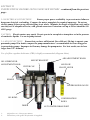
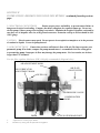
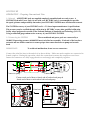
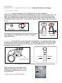
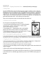
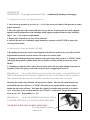
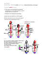
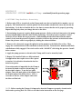
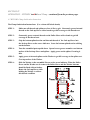
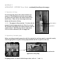
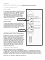
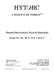
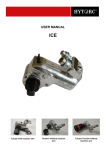
XXI/Avanti/Stealth SERIES
Operational Manual
July 2004
Table of Contents
XXI/Avanti/Stealth SERIES Operational Manual
SECTION I
IMPORTANT SAFETY INSTRUCTIONS
SECTION II
BEFORE USE
2-1 Working Pressure
2-2 Hydraulic Connections
2-3 Electrical Connections
2-4 Air Connections
SECTION III
OPERATION
3-1 General
3-2 Connecting the System
3-3 Drive Direction Change
3-4 Reaction Arm XXI/Avanti
3-5 Setting Torque
3-6 Setting Pump Pressure
3-7 Tightening Procedures
3-8 Operating the XXI, Avanti & Stealth Systems
3-9 Loosening Procedures
SECTTION IV
4-1 Tool set up and operation
USE WITH LoaDISC
4-2 LoaDISC Tensioning
WASHER & CLAMP-NUT 4-3 LoaDISC De-tensioning
4-4 LoaDISC Lubrication
4-5 CLAMP-NUT Tensioning
4-6 Clamp-nut De-tensioning
4-7 Clamp Lubrication
SECTTION V
5-1 General Information
OPERATION
5-2 Hydraulic Connections
HYTORC POWER PACKS 5-3 Prior to Use
5-4 Operation –Electric Pump-5-5 Operation –Air Pump-5-6 Automatic Pump
5-7 Starting with Automatic System
SECTION VI
HELPFUL
INFORMATION
Tool Dimensions & Parts List
Field-proven Torquing Procedure
Pressure/Torque & Pressure/Load Conversion Chart
Recommended Torque For ASTM A193 Grade B7 Studs
INTRODUCING THE NEW GENERATION HYTORC
Thank you for buying the NEW HYTORC FREEDOM-LINE!
This manual is designed to provide you with the basic knowledge required to operate and maintain
your HYTORC bolting equipment. Please read this manual carefully and follow the instructions
provided. If you have any questions regarding HYTORC bolting equipment, please call us at
201-512-9500 or contact us at [email protected].
Your purchase of HYTORC bolting equipment entitles you to the following services at no extra
cost to you.
Free on-site training in the application and operation of your HYTORC bolting equipment
* Free semi-annual training
* Free annual tool inspection.
* Free loner tools in case of failure under warranty
* Free engineering assistance by calling 1-800-FOR-HYTORC or our international office.
Your local HYTORC bolting specialist is available around the clock for your convenience. Should
you require any assistance, please contact us to obtain our local specialist’s information.
World-wide Warranty
HYTORC bolting equipment is engineered to the latest technological standards and is accompanied
by our exclusive 12 word, 12-month warranty:
“YOU BREAK IT UNDER NORMAL USE, WE FIX IT FREE OF CHARGE!”
If your HYTORC equipment cannot be repaired on site, FREE loaner equipment will be made
available to you upon request, while under warranty.
INTRODUCTION
HYTORC tools are uniquely multi-purpose. They can be used as accurate bolting
equipment on conventional nuts in open or confined spaces. They also can be used as
reaction arm free tensioning equipments, when used with HYTORC LoaDISC washer or
HYTORC-Clamp, Hydraulically Actuated Mechanical Tensioner.
SECTION I
IMPORTANT SAFETY INSTRUCTIONS
HYTORC tools are designed for the safety of operators. However, they are powerful tools and certain
safety precautions should be observed to avoid accidents or personal injury. The following tips will
assist you.
READ ALL INSTRUCTIONS
KEEP WORK AREA CLEAN AND WELL LIT
CONSIDER WORK AREA
ENVIRONMENT
Electric pumps should never be used in any atmosphere
which can be considered potentially volatile. If there is any
doubt, use an air pump.
Also note: Metal to metal contact can cause sparks. Precautions must be taken.
AVOID PREMATURE TOOL
STARTING
The pump remote control should be operated by a
designated operator and ensure “ALL CLEAR” prior to
starting and to avoid premature tool starting.
STAY CLEAR DURING OPERATION
In most cases, the tool will allow “hands free” operation. If
the tool must be reset on bolt during operation, make sure the
remote control operator is aware of turning the pump off.
IMPORTANT NOTE: NEVER HOLD THE TOOL DURING OPERATION!
GUARD AGAINST ELECTRIC
SHOCK
Ensure the pump is properly grounded and the proper
voltage is used.
STORE EQUIPMENT PROPERLY
When not in use, tools and accessories should be properly
stored to avoid deterioration.
USE THE RIGHT TOOL
Do use tools or attachments suitable for the applications.
*refer to our recommended torque/load chart
PROPER SAFETY ATTIRE
When handling/operating hydraulic equipment, wear
work gloves, hard hats, safety shoes, safety glasses and other
applicable clothing.
MOVING EQUIPMENT
Do not use hydraulic hoses, uniswivels, pump power or
remote cords as means of moving the equipment.
SECTION II
INSTRUCTIONS BEFORE USING YOUR NEW HYTORC -continued from the previous
page2-3 ELECTRICAL CONNECTIONS
Ensure proper power availability to prevent motor failure or
dangerous electrical overloading. Compare the motor nameplate for required amperage. Do not use
electric pump, if three prong electrical plug is not whole. Minimize the length of extension cords and be
sure they are of adequate wire size, with ground connectors. Extension cord up to 50 feet should be #10
AWG gauge.
CAUTION: Electric motors may spark. Do not operate in an explosive atmosphere or in the presence
of conductive liquids. Use an air pump instead.
2-4 AIR CONNECTIONS Ensure that you have sufficient air flow of 80 psi ( 50 cfm) to operate your
pneumatic pump. If in doubt, compare the pump manufacturer’s recommended air flow rating prior
to pressurizing pump. Improper air flow may damage the pump motor. For best results, use air hose
larger than 3/4 “ diameter.
Use of a filter regulator lubricator (FRL) is highly recommended. (diagram below)
AIR ADJUSTMENT KNOB
MOUNT BRACKET
OIL LUBRICATOR
ADJUSTMENT KNOB
FILTER CAP
AIR FLOW
ON/OFF LEVER
ELBOW
AIR PRESSURE GAUGE
OIL BOWL
CONDENSATION
BOWL
DRIER
1.
2.
Adjust flow to 1-2 drops per minute.
Fill half way with grade 46 hydraulic oil supplied.
AUTO WATER DRAIN PORT
SECTION II
INSTRUCTIONS BEFORE USING YOUR NEW HYTORC
READ CAREFULLY: Most malfunctions, in new equipment, are the result of improper operation
and/or set-up.
PREPARATION: Remove HYTORC equipment from shipping container.
INSPECTION: Visually inspect all components for any damage during transportation. If damages
are found, notify HYTORC immediately.
2-1 Working Pressure
The tool’s maximum
working pressure is 10,000 PSI (700kg/cm2, 690 Bar)
Make sure that all hydraulic equipment used is rated
for 10,000 PSI operating pressure. To set pump
pressure for XXI models to 10,000 PSI for both
advance & retract, locate selector valve underneath
the couplers. Turn the pump off and loosen the lock
nut. Turn the center screw counter-clockwise until
it stops. Tighten the lock-nut. For Avanti & Stealth
models, turn the center screw clockwise until it stops.
Tighten the lock-nut to set the pump pressure to 1,500
PSI for retract.
2-2 Hydraulic Connections With older style pumps, (SST-10, SST-20),
the retract side of the system may remain pressurized after the pump
has been switched “off”. This trapped pressure makes it impossible to
loosen the retract-side fittings by hand. To release the pressure, find
the 5/16 manual override holes in the end of the black solenoids on the
pump. With a welding rod, Allen-key or similar device, push in on the
ends of both solenoids, each in turn, and the residual pressure will be
released. All fittings will, then, be hand tightened again. Hoses and
couplers must be free and unobstructed before and during the operation
of the tool. External impact on the couplers may break off the fittings.
Current pump models are equipped with an auto-pressure relief. Never disconnect or connect any
hydraulic hoses or fittings without first unloading wrench and the pump. Double check the gauge
reading to assure pressure has been released.
When making connections with quick disconnect couplings, make sure the couplings are fully engaged.
Threaded connections such as fittings and gauges must be clean and securely tightened and leak free.
CAUTION: Loose or improper threaded fittings can be potentially dangerous if pressurized. Severe
over tightening can cause premature thread failure. Never grab, touch or in any way come in contact
with a hydraulic pressure leak. Escaping oil can penetrate the skin and cause injury.
SECTION II
INSTRUCTIONS BEFORE USING YOUR NEW HYTORC -continued from the previous
page2-3 ELECTRICAL CONNECTIONS
Ensure proper power availability to prevent motor failure or
dangerous electrical overloading. Compare the motor nameplate for required amperage. Do not use
electric pump, if three prong electrical plug is not whole. Minimize the length of extension cords and be
sure they are of adequate wire size, with ground connectors. Extension cord up to 50 feet should be #10
AWG gauge.
CAUTION: Electric motors may spark. Do not operate in an explosive atmosphere or in the presence
of conductive liquids. Use an air pump instead.
2-4 AIR CONNECTIONS Ensure that you have sufficient air flow of 80 psi ( 50 cfm) to operate your
pneumatic pump. If in doubt, compare the pump manufacturer’s recommended air flow rating prior
to pressurizing pump. Improper air flow may damage the pump motor. For best results, use air hose
larger than 3/4 “ diameter.
Use of a filter regulator lubricator (FRL) is highly recommended. (diagram below)
AIR ADJUSTMENT KNOB
AIR FLOW
ON/OFF LEVER
OIL LUBRICATOR
ADJUSTMENT KNOB
FILTER CAP
AIR PRESSURE GAUGE
CONDENSATION
BOWL
DRIER
1.
2.
Adjust flow to 1-2 drops per minute.
Fill half way with grade 46 hydraulic oil supplied.
AUTO WATER DRAIN PORT
SECTION III
OPERATION – Torquing Conventional Nuts
3-1 General All HYTORC tools are supplied completely assembled and are ready to use. A
HYTORC Hydraulic Power Pack, for use with your HYTORC tools, is recommended to provide
the speed, pressure and portability that makes your HYTORC SYSTEM more efficient and accurate.
The SYSTEM accuracy of your HYTORC tool is +-3% based upon manufacturer’s specifications.
This accuracy maybe certified through calibration by HYTORC or any other qualified calibration
facility whose program is traceable to the National Institute of Standards and Technology (N.I.S.T.)
Using a calibrated gauge enhances the accuracy of your HYTORC SYSTEM.
3-2 Connecting the SYSTEM
The wrench head and power pack are connected by a
10,000 PSI operating pressure (40,000 PSI burst) twin line hose assembly. Each end of the hose have
one male and one female connector to assure proper interconnection between pump and wrench
head.
IMPORTANT:
To avoid tool malfunction, do not reverse connectors.
Connect the twin line hose to the uniswivel as shown below. Make sure male couplers are connected to
female couplers. During the operation, check the connection to ensure the couplers are not loose.
Insure the connectors are fully engaged and screwed snugly and completely together.
Connect to tool
Connect to pump
*Connect male end of hose to female end of both tool and pump &
female end of hose to male end on both tool and pump
From hose
From hose
SECTION III
OPERATION – Torquing Conventional Nuts -continued from the previous page3-3 Drive Direction Change
Avanti tools To remove the square drive, disengage the drive retainer assembly by
depressing the retaining round button and gently pulling on the square end of the square drive. The
square drive will slide out. To insert the drive in the tool, place the drive in the desired direction,
engage drive spline and ratchet spline, then twist bushing until engage to the housing spline. Push
drive through ratchet. Depress drive retainer button, engage retainer with drive and release button
to lock.
Button
Drive Retainer
Square Drive
The diagram on the right illustrates the direction that the square
drive should face for tightening and loosening of a standard
right hand fastener.
Loosening
Tightening
Stealth tools The Stealth tools use interchangeable ratcheting links. For tightening, simply engage
the nut with the right side of the link facing down. For loosening, the left side of the link faces down.
Ratcheting link can be detached from the Stealth power head by pulling the power head out while
pressing the button shown below.
STEALTH
MADE IN U.S.A.
STEALTH
MADEIN USA
Loosening
Link release button
3-4 Reaction Arm
Please read
operating
instructions
prior to use,
and use
common sense.
Tightening
KEEP HANDS
OFF DURING
OPERATION!
The Avanti can be used with a 360 degree adjustable universal reaction arm.
Make sure the reaction arm spline is fully
engaged on the square drive spline. Secure
the position by tightening the set screw on
the reaction arm.
*ALWAYS USE A SAFETY HANDLE
SECTION III
OPERATION – Torquing Conventional Nuts -continued from the previous page3-5 Setting Torque
Once the SYSTEM is fully connected and the proper power supply is available, it is time to adjust the
pump pressure to the level needed on your job. When tightening, use the manufacturer’s specifications
to determine the torque value ultimately required. Appendix I – which is presented as a guideline for
comparison only – gives typical torque values specified for the most commonly encountered fasteners.
Torque sequence varies from plant to plant and even within the same plant may vary depending on the
gasket material and other factors. Always abide by on-site-procedures.
Always refer to the pressure-torque conversion table that came with the tool.
3-6 Setting the Pressure on the Pump
T Handle
To set the pressure on the pump, follow this procedure.
1. Loosen the knurled locking ring below the “T” handle on the pump’s
external pressure regulator. Then turn the “T” handle counterclockwise until it turns freely and easily.
2. Turn the pump “ON”. Using the pump’s remote control pendant,
push down the advance switch (or button on air pump) and hold it.
Locking Ring
3. While holding the pump in the advance mode, slowly turn the “T” handle
clockwise and observe the pump pressure gauge rise.
NOTE: Always adjust the regulator pressure up – never down.
4. Once the desired pressure is reached. Turn off the pump and “LOCK IN” the pressure by tightening
the knurled lock nut. Turn on the pump once more and pressurize to verify the pressure is maintained.
3-7 Applying the Avanti – the Tightening Process
1. Once your target pressure is set, cycle the tool three or four times to full pressure. Cycling the tool
ensures that the system is operating properly and removes trapped air, if any.
2. Place the proper size driving unit on the square drive and secure properly.
3. Place the tool on the bolt, making sure that everything is fully engaged. Further ensure that the drive
retainer is engaged.
4. Make sure the reaction arm is firmly abutted against a stationary object.
5. When positioning the wrench, make sure that the hose connections are well clear of any obstructions.
6. After all the above are confirmed, apply momentary pressure to the SYSTEM to ensure proper tool
placement.
SECTION III
OPERATION – Torquing Conventional Nuts -continued from the previous page3-7 Applying the Stealth – the Tightening Process
1. Once the target pressure is set (refer to 3-6) Cycle the tool several times to full pressure to assure
proper operation.
2. Place the right side of the ratchet link directly over the nut. Ensuring the hex is fully engaged
and the reaction pad portion of the link abuts solidly against an adjacent nut or other stationary
object. (see 3-3 for proper tool placement)
3. Ensure hose connections are clear of any obstacles.
4. After all the above are confirmed, apply momentary pressure to the SYSTEM to assure the
reaction point is stable.
3-8 Operating the Avanti and Stealth SYSTEMS
1. By pushing down on the remote control button in the advance position, the rear of the tool will
be pushed back until the reaction surface will contact its reaction point.
2. Continue to hold down the advance button as the socket turns until you hear a “CLICK” which
will signify the hydraulic cylinder inside the tool is fully extended and will not turn the socket
further.
3. Continuing to hold down the remote control button will result in a rapid buildup of pressure to
the point of where the gauge reads what was preset prior to applying the wrench.
IMPORTANT:
The reading of full preset pressure after the cylinder is extended DOES NOT
INDICATE that this pressure (torque) is applied to the bolt. It only indicates that the cylinder is
fully extended and cannot turn the nut further until the tool automatically resets itself.
Releasing the remote control button will retract the cylinder. The tool will automatically reset
itself and the operator will hear a “CLICK” indicating he can again push the remote control
button and the socket will turn. Each time the cylinder is extended and retracted, it is called a
cycle. Successive cycles are made until the tool “STALLS” at the preset Torque/PSI with an
accuracy of +-3%. Repeatability is +-1%.
IMPORTANT:
ALWAYS ATTEMPT ONE FINAL CYCLE
TO INSURE THE “STALL” POINT HAS BEEN REACHED.
NEVER HOLD THE TOOL DURING OPERATION.
Use safety handle to set and
remove tools.
SECTION III
OPERATION – Torquing Conventional Nuts -continued from the previous page3-8 Operating the Avanti and Stealth SYSTEMS
Releasing “LOCKED-ON” tools.
Should the tool “LOCK-ON” after the final cycle, slide the slider (or the lever on Avanti) with the
pump off or in retract position. Turn the pump back on and while maintaining the pressure, cycle
Avanti in the pump’s manual mode. Should Stealth “LOCK-ON”, advance pump pressure
and while advancing, press down on the release button located on the sides of the ratchet link.
Once you are able to press down the button without resistance, continue holding the button down
and release the advance pressure on the pump. Shut off the pump, and remove the tool from the nut.
Avanti Release Procedure
Disengage lever
1)
Push lever to position A
2)
Cycle tool in manual mode, release advance
button
3)
Shut pump off
4)
Remove tool and reset lever to position B
Stealth Release Procedure
STEALTH
1)
Push remote to full pressure for final stroke
2)
Disengage the reaction pawl by holding the
button in the direction of arrow
3)
Release the rocker switch
4)
Shut pump off
5)
Remove tool
MADE IN U. S.A.
Disengage button
SECTION III
OPERATION – Torquing Conventional Nuts -continued from the previous page3-9 Loosening Procedures Avanti and Stealth SYSTEM
First, set the pump to 10,000PSI. Set the tools for the loosening mode (Refer to 3-3), assuring the
reaction surface abuts squarely off a solid reaction point. Press and hold the remote control button
down. Pressure will decrease as the socket begins to turn. As the cylinder extends fully, you will hear
a “CLICK”. Release the remote control button and the cylinder automatically retracts, at which time
you again hear a “CLICK”. Repeat this process until the fastener can be removed by hand.
NOTE:
If the bolt does not loosen with the above procedure, it is an indication that you may
require the next larger size tool to loosen the bolt. Corroded nuts and thread galling on bolts can
cause difficulty in loosening. Please consult your HYTORC bolt specialist.
SECTION IV
OPERATION – HYTORC LoaDISC and Clamp
4-1 Tool Set up and Operation
When used in conjunction with the HYTORC LoaDISC Washer or Clamp, the operation is essentially
the same as with the conventional nuts, but with one notable exception: THERE ARE NO
REACTION FORCES TO CONSIDER OR PROVIDE FOR! The reaction forces are absorbed
through the fastener assembly itself. Each individual customer order for LoaDISC or Clamps will be
provided with specific installation instructions for each application. However, the following general
guidelines outline correct installation procedures.
4-2 HYTORC LoaDISC Tensioning
1. Do not use grease or lubricants on LoaDISC , nut, bolt or joint face. LoaDISC is “DRY LUBE”
protected.
2. Place the LoaDISC over the bolt with the flat surface firmly against joint face.
3. Install the nuts on the bolt and hand tighten snugly on both sides of assembly.
4. Set required pump pressure.
5. Place tooling to engage a nut and the LoaDISC with “TIGHTENING” side facing the operator.
-continued to the next page-
DRIVE SOCKET
HOLDING SOCKET
Soft Joint LoaDISC
Reusable LoaDISC
Hard Joint LoaDISC
Limited Clearance
HEX NUT
DISC WASHER
THREADED SEGMENT
LoaDISC
SECTION IV
OPERATION – HYTORC LoaDISC and Clamp -continued from the previous page4-2 HYTORC LoaDISC Tensioning
6. Verify proper socket engagement by momentarily
pressurizing tool. If tool remains stationary, operate
normally until tool “STALLS OUT”
7. Should tool rotate during initial pressurizing:
A. Insure both socket and sleeve are fully engaged.
B. Insure that joint faces are free from grease and oil.
*Also refer to the trouble shooting section (4-4)
LoaDISC Driver Installation
for Tensioning
LOCK-RING
'NEUTRAL'
POSITION
PLACE DRIVER
NUT/LoaDisc
ROTATE 'CW'
BY HAND, TO
SNUG LoaDisc
TO FLANGE
LoaDisc
LOCK-GROOVE
NOTE:
ROTATE
DRIVER
ASSEMBLY
'CCW'
DIRECTION
FOR
TIGHTEN
MODE
TIGHTEN
'CCW'
DIRECTION
LOOSEN
'CW'
DIRECTION
1
2
3
* DO NOT GRAB A SWIVEL DURING OPERATION!
* DO NOT PLACE TOOL HOUSING
* TO ABUT AGAINST STATIONARY OBJECTS
* DO NOT STAND UNDERNEATH OR
CLOSE TO TOOL
* DO NOT RE-USE SINGLE-TIME
USE LoaDISC
VERIFY
ROTATE
LOCK-RING
LOCK-RING
ENGAGE
LoaDisc
LOCK-GROOVE
4
5
SECTION IV
OPERATION – HYTORC LoaDISC and Clamp -continued from the previous page4-3 HYTORC LoaDISC De-tensioning
1. Set pump to maximum pressure.
2. Place tooling to disengage the nut and the LoaDISC with “LOOSENING” side facing the operator.
3. Verify proper socket engagement by momentarily pressurizing tool. If tool remains stationary,
operate normally until the nut is loose.
4. Should tool rotate during initial pressurizing:
A. Insure both socket and sleeve are fully engaged.
B. Insure that joint faces are free from grease and oil.
*Also refer to the trouble shooting section (4-4)
ROTATE
DRIVER
ASSEMBLY
'CW'
DIRECTION
FOR
LOOSEN
MODE
LoaDISC Driver Installation for De-tensioning
VERIFY
ROTATE
LOCK-RING
3
4
5
Releasing “LOCKED-ON” tools. (Refer to 3-8 for Avanti and Stealth)
Should the tool “LOCK-ON” after the final cycle, slide the slider with the pump off or in retract
position. Turn the pump back on and while maintaining the pressure, cycle XXI in the pump’s
manual mode. the pump. Shut off the pump, and remove the tool from the nut.
XXI Release Procedure
HYT RC
1)
Push slide cover up to position A
2)
Cycle tool in manual mode, release advance
button
3)
Shut pump off
4)
Remove tool and reset slide cover to position B
SECTION IV
OPERATION – HYTORC LoaDISC and Clamp -continued from the previous page4-4 HYTORC LoaDISC Lubrication Instruction & Trouble Shooting
STEP 1:
Make sure all threads and surfaces are free of dirt or grit.
STEP 2:
Apply spray lube TS801 moly spray to nut per procedure indicated below. Allow
spray lube to dry (spray lube is shipped with LoaDISC order). Refer to the Dry-lube
container label for a drying time. Do Not Apply Lube to LoaDISC
STEP 3:
Clean and dry protruding stud threads and nut seat surfaces.
STEP 4:
Install LoaDISC with flat side against joint, turn till snug.
STEP 5:
Install lubricated hex nut on top of LoaDISC , snug against top surface of LoaDISC .
LoaDISC Application of Spray TS801
NOTE:
*Allow sufficient time for spray to dry
before use.
Hex nut can be reused, if re-lubricated
per illustration.
NO NOT REUSE ONE TIME USE LoaDISC
HYTORC LoaDISC Trouble Shooting
SYMPTOM
Driver does not lock
CAUSE
Lock ring misaligned with
LoaDISC
SOLUTION
Check for excessive stud protrusion
Check that holding socket is flush to
flange surface
LoaDISC groove damaged
Replace LoaDISC
Missing or damage lock-ring
Replace lock-ring
LoaDISC not snug against
flange surface
Tighten LoaDISC to flange surface
with driver assembly (CW direction)
Driver un-locks during
verification
Worn lock-ring
Replace lock-ring
Driver un-locks during
use
Lock-ring rotated in wrong
direction
Rotate Holding socket and lock-ring
•CCW toward ‘T’ for Tighten
•CW toward ‘L’ for Loosen
Driver does not un-lock
after torque procedure
Stud driven up into bottom of
drive socket
Check for excessive stud extension.
SECTION IV
OPERATION – HYTORC LoaDISC and Clamp -continued from the previous page4-5 HYTORC Clamp Installation - Tensioning
The HYTORC Clamp is provided with lubrication and is shipped ready for use. For re-lubrication,
please refer to lubrication Instructions. (4-6)
1. Thread the Clamp down on the stud, turn the Puller Sleeve to contact the flange, contacting the
flange or the spot face firmly. The Clamp should fit easily onto the spot face.
2. The Puller Sleeve, when properly installed, should protrude no more than 1/16 (15mm) past the
top of the Nut (outside sleeve). If the Puller Sleeve is raised beyond 1/16”, hold the Puller Sleeve or
the Bridge by hand and turn the Nut counter-clockwise (loosen direction) until the Puller Sleeve
protrudes no more than 1/16” past the top of the Nut. After adjusting the Nut, turn the entire Clamp
assembly down to contact the flange or the spot face firmly.
3. Before using XXI tool on the Clamp, make sure the tool and the drive member are set properly.
The castellated drive and the splined reaction member should stick out on the right side for
tensioning. Cycle the tool and the drive a few times to ensure that the tool is properly operating.
Repeat this step only when you change the tool or the drive.
4. Refer to the load chart supplied with the Clamp and set the pump pressure to achieve the desired
load. Do not engage drive on the Clamp while setting the pump pressure. Turn the pressure
regulator counter-clockwise to set it below the target pressure. While holding the advanced button
on the remote control, slowly turn the pressure regulator clock wise to increase the pressure to the
desired value. Ensure the pressure value is set properly by holding the advanced button.
5 Before applying the tool and the drive, engage the splined reaction member to the Puller Sleeve
first. Then engage the castellated drive to the castellated section of the Nut. Turn the drive manually
until both castellation are fully engaged.
IMPORTANT: If the castellated teeth do not fully engage, the Puller Sleeve is sticking up too far or
stud protrusion is more than maximum value. Refer back to Step 3. Then reposition the Puller
Sleeve and check stud protrusion.
6 Apply the pump pressure to tension the Clamp, until the target pressure is reached. To ensure that
the proper tension has been applied to the stud, allow the tool to fully retract then advance to the
target pressure a final time.
7 Repeat 5 & 6 until all bolts are fully tensioned.
SECTION IV
OPERATION – HYTORC LoaDISC and Clamp -continued from the previous page4-6 HYTORC Clamp Installation - Detensioning
1. Before using XXI or Avanti tool on the Clamp, make sure the tool and the drive member are set
properly. The castellated drive and the splined reaction member should stick out on the left side for
detensioning. Cycle the tool and the drive a few times to ensure that the tool is properly operating.
Repeat this step only when you change the tool or the drive.
2. Detensioning, in general, requires higher pump pressure. Refer to the load chart and set the pump
pressure slightly higher than the value used for tensioning. Turn the pressure regulator counter
clockwise to set it below the target pressure. While holding the advanced button on the remote
control, slowly turn the pressure regulator clockwise to increase the pressure to the desired value.
Ensure the pressure value is set properly by holding the advanced button.
3. Remove drive from tool, engage the splined reaction member to the Puller Sleeve first. Then
engage the castellated drive to the castellated section of the Nut. Turn the drive manually until both
castellation are fully engaged. Place tool on drive with “LOOSEN” side facing the operator. Install
drive retainer.
4. Apply the pump pressure to detension the Clamp, until it can be turned by hand.
5. Repeat 3 & 4 until all bolts are fully tensioned.
On applications that require two or three passes
to tension, it is advised to detension the last few
bolts in two passes.
If corrosion makes it impossible for the Clamp to
be turned by hand even after detensioning, use
the hex/spine adaptor. To use the hex/spline
adaptor, insert the male spline of the adaptor into
the female spline of the Puller Sleeve. Place a
wrench over the hex of the adaptor and rotate
the Sleeve off the bolt.
NOTE: Before reusing the Clamps, it is imperative that the Clamps are properly cleaned and re
lubricated to prolong their life. Refer to the lubrication instruction on the next page.
SECTION IV
OPERATION – HYTORC LoaDISC and Clamp -continued from the previous page4-7 HYTORC Clamp Lubrication Instruction
The Clamp Lubrication Instructions: (Use a clean stiff bristle brush)
STEP 1:
Make sure all threads and splines are free of dirt or grit. Generously grease internal
threads on the Jack-up Sleeve with a brush to get full coverage to the thread root.
STEP 2:
Generously grease external threads on the Puller Sleeve with a brush to get full
coverage to the thread root.
STEP 3:
Grip the bottom splined section and internal threads of the Jack-up Sleeve into
the Jack-up Sleeve as the arrow indicates. Leave the bottom splined section sticking
out the bottom.
STEP 4:
Turn the assembled parts upside-down. Spread excess grease around to coat bottom
surface of the Jack-up Sleeve and splines. Apply grease on the splines if coating is
thin.
STEP 5:
Apply grease to internal splines on the Washer to get full coverage to the spline root.
Coat top surface of the Washer.
STEP 6:
Slide the Washer to the assembled Sleeves as the arrow indicates. When the Puller
Sleeve and the Washer are in contact, the Puller Sleeve and the Washer bottoms
should be flush with each other.
Rotate the Jack-up Sleeve while
holding the Washer to achieve
this desired condition.
SECTION V
OPERATION – HYTORC Power Packs
5-1 HYOTRC Power Packs General Information
All HYTORC Power Packs operate at a pressure range from 500 to 10,000 PSI and are fully
adjustable. They have been engineered and designed for portability and high flow for increased
speed. Before using your HYTORC Power Pack, check the following points:
•
•
•
•
•
Is the reservoir filled with oil?
Where is the closest electrical outlet at the job site? (Electric pump only)
Is there enough air pressure (100 PSI) and flow (50 CFM) at the job site? (Air units only)
Is the gauge mounted and rated for 10,000 PSI
Is the oil filler plug securely in place?
The Power Packs maximum working pressure is 10,000 PSI (700 kg/cm2, 690 Bar) Make sure all
hydraulic equipment and accessories are rated for 10,000 PSI operating pressure.
5-2 Hydraulic Connections
When making a connection with quick connect couplings, make sure the couplings are fully
engaged. Threaded connectors such as fittings, gauges etc. must be clean and securely tightened and
leak free.
CAUTION: Loose or improperly threaded couplers can be potentially dangerous if pressurized.
Severe over tightening can cause premature thread failure. Knurled sleeve on couplers need to be
only hand tight. Never grab, touch or in any way come in contact with a hydraulic pressure leak.
Escaping oil can penetrate the skin and cause injury. Do not subject the hose to potential hazard
such as sharp surfaces, extreme heat or heavy impact. Do not allow the hose to kink and twist.
Inspect the hose for wear before each usage.
5-3 Prior to Use
Do not use a power or extension cord that is damaged or has exposed wiring. All single phase motors
come equipped with a three prong grounding type plug to fit the proper grounded type electrical
outlet. Do not use a two prong ungrounded extension cord as the pump’s grounded type electrical
outlet. Compare motor nameplate against power availability to prevent motor burnout or dangerous
electrical overloading.
*For electric cord extension, refer to below chart
0-25 Foot Extension
26-50 Foot Extension
51-75 Foot Extension
76-100 Foot Extension
Use size 12 gauge cord
Use size 10 gauge cord
Use size 8 gauge cord
Use size 6 gauge cord
Check hydraulic oil level to prevent possible pump burnout.
Look at oil fill level on the oil sight gauge. The oil level
should be approximately 2” from the top of the reservoir
plate-with motor off. Add HYTORC oil as necessary.
*Do not mix different grades of oil.
Air Pump Oil Sight Gauge
Electric Pump Oil Sight Gauge
SECTION V
OPERATION – HYTORC Power Packs -continued from the previous page5-3 Prior to Use -ContinuedMake sure all desired gauge, valve, hose and quick coupler connections are tight and secure. The
gauge permits the operator to monitor the load on the wrench.
*Calibrated gauges are available for most application.
Before starting your HYTORC pump, connect your hydraulic hoses to both the pump and torque
wrench. (Refer to 3-2)
5-4 Operation Electric Pump
Push the rocker switch on the hand control pendant in the OFF
position. Then, depress and release the safety button.
NOTE: The safety button is an added feature designed to
prevent premature starting and should only be depressed by
the tool operator.
Push the rocker switch to advance position and release
it. This will start your pump and place it in the retract
position. Your HYTORC electric pump has been
designed with an auto shut off system. The pump will
shut off after approximately 20 seconds of non-cycling.
This will prevent overheating or unnecessary wear and
results in longer life of your pump. To restart the
pump, depress the safety button again.
Safety Button
OFF
Retract/Neutral
Advance
Rocker Switch
5-5 Operation Air Pump
Before connecting air supply line to the Air Filter Lubricator, make sure the Air Flow Lever is in the
OFF position. Then connect air supply line. Open the Air Flow Lever. Check the PSI reading on the
Air Pressure Gauge. It should be at 100 psi. Depress
the Air Adjustment Knob to increase psi reading.
Air Adjustment Knob
Air Flow Lever
Adjust lubricator to approximately one drop per
Lubricator Adjust
Minute.
*Before operating your HYTORC air pump,
check for air leaks on the air hoses/tubing.
Air Pressure gauge
SECTION V
OPERATION – HYTORC Power Packs -continued from the previous page5-5 Operation Air Pump
To start the pump, depress the advance button and
release it. This will put the tool in the retract mode.
To advance the tool, depress the advance button and
hold it down. When you are done, depress the stop
button and the motor will stop.
NOTE: The pump is still pressurized. To release the air
pressure from the pump, put the Air Flow Lever in the
OFF position, then depress the advance button on the air
remote control. This will purge the air in the motor.
Now it is safe to disconnect your air supply line.
Advance Button
Stop Button
5-6 Operation of automatic pump
Before operating automatic pump, the cable line attached to each hose must be connected securely
with the appropriate receptacle on the pump manifold and the receptacle on the tool.
Securely connect
NOTE: Connect only the number of tools used on the
application to the pump.
Set pump pressure to achieve desired torque value. (refer to 3-5 and 3-6)
SECTION V
OPERATION – HYTORC Power Packs -continued from the previous page5-7 Starting with automatic operation
MANUAL MODE
For manual operation, depress the Mode [M] 3-position
rocker switch to the ‘MANUAL’ position. Hold down
the Control [C] rocker switch in the ‘RUN’ position to
advance the tool(s). The switch will toggle to the
‘NEUTRAL’ position when released, retracting the
tool(s). Depress the Control [C] switch to the ‘OFF’
position to turn off the system.
AUTOMATIC MODE
CONTROL SWITCH
PERSS FOR RUN
(TOOL ADVANCE)
RELEASE (TOOL RETRACT)
(NEUTRAL)
PRESS FOR PUMP OFF
Initialize Computer:
To operate the automatic system, the computer has to
recognize how many tools are attached to the system.
To accomplish this, attach the required number of tools
to both hydraulic and electric lines. Then cycle system
in manual mode for at least one full cycle.
PRESS FOR TIGHTENING
NEUTRAL LOOSENING
PRESS FOR MANUAL
MODE SWITCH
AUTOMATIC TIGHTENING MODE
Initialize the computer (see above). Without shutting
pump off, push Mode switch [M] into ‘TIGHTENING’
position. Press and hold control switch [C] in ‘RUN’
position. As long as the run switch is held depressed,
the pump will function in automatic tightening mode.
The tool(s) will continue to cycle until the preset torque
Is achieved. Allow sufficient time to be sure that the
tool(s) have stopped rotating before releasing the run
switch. The pump motor will automatically shut off
after 20 seconds, allowing the tool(s) to return to the
retract position. The ‘OFF’ position on the Control
switch turns off the system.
AUTOMATIC LOOSENING MODE
Initialize the computer (see above). Without shutting
pump off, push Mode switch [M] into ‘LOOSENING’ position. Press and hold control switch [C]
in ‘RUN’ position. As long as the run switch is held depressed, the pump will function in automatic
loosening mode. The tool(s) will continue to cycle until the Control switch is released. Cycle tool(s)
until nuts are free and can be removed by hand. Release the Control switch and depress the Control
switch to the ‘OFF’ position to complete the loosening cycle.