1
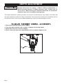
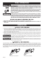
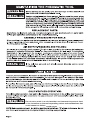
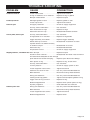
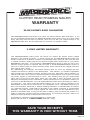
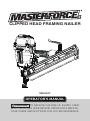
CLIPPED HEAD FRAMING NAILER
208-5017
OPERATOR'S MANUAL
CAUTION: TO REDUCE THE RISK OF INJURY, USER
MUST READ AND UNDERSTAND OPERATOR'S MANUAL.
SAVE THESE INSTRUCTIONS FOR FUTURE REFERENCE.
TABLE OF CONTENTS
Safety Instructions .......................................................... Page 2
Air Supply: Fittings, Hoses, Filters, Air Consumption, Regulators,
Operation Pressure, Setting Correct Pressure ............... Page 5
Production specifications ................................................ Page 6
Depth Adjustment ........................................................... Page 7
Loading the Tool ............................................................. Page 8
Tool Operation ................................................................ Page 9
Maintaining the Pneumatic Tool ..................................... Page 11
Trouble Shooting ............................................................ Page 12
Page 1
SAFETY INSTRUCTIONS
The purpose of safety symbols is to attract our attention to possible dangers. The safety
symbols, and the explanations with them, deserve your careful attention and understanding.
The symbol warnings do not by themselves eliminate any danger. The instructions and
warnings they give are no substitutes for proper accidents prevention measures.
Be sure to read and understand all safety instruction in this
manual, including all safety alert symbols such as "DANGER", "WARNING" and
"CAUTION", before using this pneumatic tool.
SYMBOL SAFETY ALERT: Indicates DANGER, WARNING, or CAUTION. May be
used in conjunction with other symbols or photographs.
Failure to obey this safety warning WILL result in death or serious injury
to yourself or others. Always follow the safety precaution to reduce the risk of fire and personal
injury.
Failure to obey this safety warning CAN result in death or serious
injury to yourself or others. Always follow the safety precaution to reduce the risk of fire and
personal injury.
Failure to obey this safety warning MAY result in personal injury to
yourself or others, or property damage. Always follow the safety precaution to reduce the risk
of fire and personal injury.
Page 2
SAFETY INSTRUCTIONS
1. EYE PROTECTION which conforms to
ANSI specifications and provides protection
against flying particles both from the FRONT
and SIDE should ALWAYS be worn by the
operator and others in the work area when
connecting to air supply, loading, operating
or servicing this tool. Eye protection is
required to guard against flying fasteners
and debris, which could cause severe eye
injury.
2. The employer and/or user must ensure
that proper eye protection is worn. Eye
protection equipment must conform to the
requirements of the American National
Standards Institute, ANSI Z87.1 and provide
both frontal and side protection.
3. NOTE: Non-side shielded spectacles and
face shields alone do not provide adequate
protection.
Additional Safety
Protection will be required in some
environments. For example, the working
area may include exposure to noise level
which can lead to hearing damage. The
employer and user must ensure that any
necessary hearing protection is provided
and used by the operator and others in
the work area. Some environments will
require the use of head protection
equipment. When required, the employer
and user must ensure that head
protection conforming to ANSI Z89.1 is
used.
4.
Dress properly. Do not wear loose
clothing or jewelry. Contain long hair. Keep
your hair, clothing, and gloves away from
moving parts.
5. Keep fingers away from trigger when not
driving fasteners to avoid accidental firing.
6. Do not overreach. Keep proper footing
Page 3
and balance at all times. Proper footing and
balance enables better control of the tool in
unexpected situations.
6. Do not use on a ladder or unstable
support. Stable footing on a solid surface
enables better control of the tool in
unexpected situations.
7. Tool service must be performed only by
qualified repair personnel. Service or
maintenance performed by unqualified
personnel may result in a risk of injury.
8. When servicing a tool, use only identical
replacement parts. Use of unauthorized
parts may create a risk of injury.
9.
Know your pneumatic tool. Read
operator's manual carefully. Learn its
applications and limitations, as well as the
specific potential hazards related to this
tool. Following this rule will reduce the risk
of electric shock, fire, or serious injury.
10. Always wear safety glasses with side
shields. Everyday glasses have only impact
resistant lenses. They are NOT safety
glasses. Following this rule will reduce the
risk of eye injury.
11. Protect your lungs. Wear a face or dust
mask if the operation is dusty. Following
this rule will reduce the risk of serious
personal injury.
12. Protect your hearing. Wear hearing
protection during extended periods of
operation. Following this rule will reduce the
risk of serious personal injury.
13.
Make sure the hose is free of
obstructions or snags. Entangled or snarled
hoses can cause loss of balance or footing
and may become damaged.
14. Use the tool only for its intended use.
Do not discharge fasteners into open air.
15. Use the MENARDS pneumatic tool only
for the purpose for which it was designed.
16. Use only the fasteners recommended
for this tool. Use of the wrong fasteners
could result in poor fastener feeding,
jammed fasteners, and nails leaving the tool
at erratic angles. If fasteners are not
feeding smoothly and properly, discontinue
their use immediately. Jammed and
SAFETY INSTRUCTIONS
improperly feeding fasteners could result in
serious personal injury.
17. Never use this tool in a manner that could
cause a fastener to be directed toward the
user or others in the work area.
18. Do not use the tool as a hammer.
19. Always be aware that misuse and
improper handling of this tool can cause
injury to yourself and others.
20. Never leave a tool unattended with the air
hose attached.
21. Do not operate this tool if it does not
contain a legible warning label.
22. Do not continue to use a tool that leaks air
or does not function properly.
1. Do not use supply sources which can
potentially exceed 200 P.S.I. as tool may
burst, possibly causing injury.
2. The connector on the tool must not hold
pressure when air supply is disconnected. If
a wrong fitting is used, the tool can remain
charged with air after disconnecting and thus
will be able to drive a fastener even after the
air line is disconnected possibly causing
injury.
3. Do not pull trigger or depress contact arm
while connected to the air supply as the tool
may cycle, possibly causing injury.
4. Always disconnect air supply: 1.) Before
making adjustments; 2.) When servicing the
tool; 3.) When clearing a jam; 4.) When tool is
not in use; 5.) When moving to a different
work area, as accidental actuation may
occur, possibly causing injury.
When loading tool: 1.) Never place a hand or
any other part of the body in fastener
discharge area of tool; 2.) Never point tool at
anyone; 3.) Do not pull the trigger or depress
the trip as accidental actuation may occur,
possibly causing injury.
1. Always handle the tool with care: 1.)
Never engage in horseplay; 2.) Never pull
the trigger unless nose is directed toward
the work; 3.) Keep others a safe distance
from the tool while tool is in operation as
accidental actuation may occur, possibly
causing injury.
2. The operator must not hold the trigger
pulled on contact arm tools except during
fastening operation as serious injury could
result if the trip accidentally contacted
someone or something, causing the tool to
cycle.
3. Keep hands and body away from the
discharge area of the tool. A contact arm
tool may bounce from the recoil of driving a
fastener and an unwanted second fastener
may be driven possibly causing injury.
4. Check operation of the contact arm
mechanism frequently. Do not use the tool if
the arm is not working correctly as
accidental driving of a fastener may result.
Do not interfere with the proper operation of
the contact arm mechanism.
5. Do not drive fasteners on top of other
fasteners or with the tool at an overly steep
angle as this may cause deflection of
fasteners which could cause injury.
6. Do not drive fasteners close to the edge
of the work piece as the wood may split,
allowing the fastener to be deflected
possibly causing injury.
7. Do not point the tool toward yourself or
anyone whether it contains fasteners or not.
8.
Always ensure that the workpiece
contact is fully positioned above the
workpiece. Positioning the workpiece
contact on ly partially above the workpiece
could cause the fastener to miss the
workpiece completely and result in serious
personal injury.
Page 4
Do not use oxygen,
combustible gases, or bottled gases as a
power source for this tool as tool may
explode, possibly causing injury. Keep the
tool pointed away from yourself and others
when connecting air source.
A pressure regulator with an operating
pressure of 0 - 125 p.s.i. (0 - 8.79 kg/cm2) is
required to control the operating pressure for
safe operation of this tool. Do not connect
this tool to air pressure which can potentially
exceed 200 p.s.i. (14 kg/cm2) as tool may
fracture or burst, possibly causing injury.
Install a male plug on the tool which is free
flowing and which will release air pressure
from the tool when disconnected from the
supply source.
Air hoses should have a minimum of 150
p.s.i. (10.6 kg/cm2) working pressure rating or
150 percent of the maximum pressure that
could be produced in the air system. The
supply hose should contain a fitting that will
provide "quick disconnecting" from the male
plug on the tool.
Use only clean regulated compressed air as a
power source for this tool. NEVER USE
OXYGEN, COMBUSTIBLE GASES, OR
BOTTLED GASES, AS A POWER SOURCE
FOR THIS TOOL AS TOOL MAY EXPLODE.
Page 5
Do not exceed recommended maximum
operating pressure wear will be greatly
increased. The air supply must be capable
maintaining the operating pressure at the
tool. Pressure drops in supply can reduce
the tool's driving power. Refer to
SPECIFICATIONS" for setting the correct
operating pressure tool.
Dirt and water in the air supply are major
causes of wear in pneumatic tools. A filter
will help to get the best performance and
minimum wear from the tool. The filter must
have adequate flow capacity for the specific
installation. The filter has to be kept clean to
be effective in providing clean compressed
air to the tool. Consult the manufacturer's
instructions on proper maintenance of your
filter. A dirty and clogged filter will cause a
pressure drop which will reduce the tool's
performance.
PRODUCTSPECIFICATIONS
SPECIFICATIONS
PRODUCT
DRIVING POWER . . . . . . . . . . . . . . . . . . . . . . . . . . . . . . . . . . . . . . . . . . . . . . . . . . . . 1001 in.lbs
FASTENER TYPE . . . . . . . . . . . . . . . . . . . . . . . . . . . . . . . . . . . . . . . . . . . CLIPPED HEAD NAIL
(.113" to .131")
FASTENER RANGE . . . . . . . . . . . . . . . . . . . . . . . . . . . . . . . . . . . . . . . . . . . . . . . . . . . 2" to 3 1/2"
MAGAZINE CAPACITY. . . . . . . . . . . . . . . . . . . . . . . . . . . . . . . . . . . . . . . . . . . . . . . . . . 80 NAILS
WEIGHT. . . . . . . . . . . . . . . . . . . . . . . . . . . . . . . . . . . . . . . . . . . . . . . . . . . . . . . . . . . . . . . . 7 LBS
OPERATION PRESSURE . . . . . . . . . . . . . . . . . . . . . . . . . . . . . . . . . . . . . . . . . . . . 70 to 120 PSI
AIR INLET. . . . . . . . . . . . . . . . . . . . . . . . . . . . . . . . . . . . . . . . . . . . . . . . . . . . . . . . . . . . . 1/4" NPT
LIGHT WEIGHT
MAGNESIUM
HOUSING
TOOL-FREE
MULTI-DIRECTIONAL
EXHAUST
REAR LOADING
MAGAZINE
SWIVEL
CONNECTOR
DRY-FIRE
LOCK OUT
NO MAR TIP
RAFTER HOOK
SELECTABLE
TRIGGER
TOOL-FREE DRIVE
DEPTH ADJUST
TOOL-FREE MULTI-DIRECTIONAL EXHAUST
The tool-free exhaust can be adjusted to any positions depending on operator preference.
SELECTABLE TRIGGER
The selectable trigger lets the operator choose between from Contact Actuation and Single
Sequential Actuation.
LIGHT WEIGHT MAGNESIUM HOUSING
The light weight magnesium housing helps reduce work fatigue.
TOOL-FREE DRIVE DEPTH ADJUST
The tool-free depth adjust lets the operator select precise driving depth of the fastener.
DRY-FIRE LOCKOUT
The dry-fire lockout extends driver life and prevents missing nails.
SWIVEL CONNECTOR
The swivel connector helps prevent hose tangles.
REAR-LOADING MAGAZINE
The rear loading magazine offers quick reloading of fasteners.
RAFTER HOOK
Rafter hook to hang tool anywhere.
NO-MAR TIPS
The no-mar tips prevent marring and denting when using the tool on softer woods.
Page 6
DEPTH ADJUSTMENT
Always disconnect air supply: 1. Before making adjustments; 2.
When servicing the tool; 3. When clearing a jam; 4. When tool is
not in use; 5. When moving to a different work area, as accidental
actuation may occur, possibly causing injury.
The depth adjustment feature provides close control of the fastener drive depth; from flush with
the work surface to shallow or deep countersink. First, set the air pressure for consistent drive in
the specific work. Then use the depth adjustment to give the desired depth of drive.
1.
2.
3.
4.
Disconnect the tool from the air supply.
Turn the depth selector left or right to change the driving depth.
Reconnect the tool to the air supply.
Drive a test nail after each adjustment until the desired depth is set.
Page 7
LOADING
• Never place a hand or any other part of the body in nail discharge
area of tool while the air supply is connected.
• Never point the tool at anyone else.
• Never engage in horseplay.
• Never pull the trigger unless nose is directed at the work.
• Always handle the tool with care.
• Do not pull the trigger or depress the trip mechanism while loading
the tool.
1. Insert nails into track of magazine.
2. Pull pusher all the way back and then allow it
to push nails forward to driving position.
Page 8
TOOL OPERATION
EYE PROTECTION which conforms to ANSI specifications and provides protection
against flying particles both from the FRONT and SIDE should ALWAYS be worn
by the operator and others in the work area when connecting to air supply, loading,
operating or servicing this tool. Eye protection is required to guard against flying
fasteners and debris, which could cause severe eye injury.
The employer and/or user must ensure that proper eye protection is worn. Eye
protection equipment must conform to the requirements of the American National
Standards Institute, ANSI Z87.1 and provide both frontal and side protection.
NOTE: Non-side shielded spectacles and face shields alone do not provide
adequate protection.
Additional Safety Protection will be required in some environments. For example,
the working area may include exposure to noise level which can lead to hearing
damage. The employer and user must ensure that any necessary hearing protection
is provided and used by the operator and others in the work area. Some environments
will require the use of head protection equipment. When required, the employer
and user must ensure that head protection conforming to ANSI Z89.1 is used.
I. READ AND UNDERSTAND THE WARNINGS CONTAINED IN THIS MANUAL.
II. REFER TO "TOOL SPECIFICATIONS" IN THIS MANUAL TO IDENTIFY THE OPERATING SYSTEM ON
YOUR TOOL.
OPERATION
A. SINGLE FASTENER PLACEMENT: To operate the tool in this manner, first position the contact trip on the
work surface, WITHOUT PULLING THE TRIGGER. Depress the contact trip until the nose touches the work
surface and then pull the trigger to drive a fastener. Do not press the tool against the work with extra force.
Instead, allow the tool to recoil off the work surface to avoid a second unwanted fastener. Remove your
finger from the trigger after each operation.
B. RAPID FASTENER OPERATION: To operate the tool in this manner, hold the tool with the contact trip
pointing towards but not touching the work surface. Pull the trigger and then tap the contact trip against the
work surface using a bouncing motion. Each depression of the contact trip will cause a fastener to be driven.
The operator must not hold the trigger pulled on contact trip tools except during fastening
operation, as serious injury could result if the trip accidentally contacted someone or
something, causing the tool to cycle.
Keep hands and body away from the discharge area of the tool. A contact trip tool may
bounce from the recoil of driving a fastener and an unwanted second fastener may be
driven, possibly causing injury.
The SEQUENTIAL TRIP MODEL contains a contact trip that operates in conjunction with the trigger to drive a
fastener. To operate a sequential trip tool, first position the contact trip on the work surface WITHOUT PULLING
THE TRIGGER. Depress the contact trip and then pull the trigger to drive a fastener. As long as the contact trip
is contacting the work and is held depressed, the tool will drive a fastener each time the trigger is depressed.
If the contact trip is allowed to leave the work surface, the sequence described above must be repeated to drive
another fastener.
Sequential Trip Operation
Page 9
Contact Trip Operation
TOOL OPERATION CHECK
Keep the tool away from yourself and others when connecting air
source.
Remove all fasteners from tool before performing tool operation
check.To reduce the risk of injury to yourself and others, check the
tool before beginning work each day or if the tool is dropped, receive
a sharp blow, been run over, etc. If the tool does not work as it should,
contact Menards service center immediately.
1. CONTACT TRIP OPERATION:
A. With finger off the trigger, press the contact trip against the work surface.
THE TOOL MUST NOT CYCLE.
B. Hold the tool off the work surface, and pull the trigger.
THE TOOL MUST NOT CYCLE.
C. With the tool off the work surface, pull the trigger. Press the contact trip against the work surface.
THE TOOL MUST CYCLE.
D. Without touching the trigger, press the contact trip against the work surface, then pull the trigger.
THE TOOL MUST CYCLE.
2. SEQUENTIAL TRIP OPERATION:
A. Press the contact trip against the work surface, without touching the trigger.
THE TOOL MUST NOT CYCLE.
B. Hold the tool off the work surface and pull the trigger.
THE TOOL MUST NOT CYCLE.
Release the trigger. The trigger must return to the trigger stop on the frame.
C. Pull the trigger and press the contact trip against the work surface.
THE TOOL MUST NOT CYCLE.
D. With finger off the trigger, press the contact trip against the work surface. Pull the trigger.
THE TOOL MUST CYCLE.
IN ADDITION TO THE OTHER WARNINGS CONTAINED IN THIS MANUAL
OBSERVE THE FOLLOWING FOR SAFE OPERATION
• Use the Masterforce pneumatic tool only for the purpose for which it was designed.
• Never use this tool in a manner that could cause a fastener to be directed toward the
user or others in the work area.
• Do not use the tool as a hammer.
• Always carry the tool by the handle. Never carry the tool by the air hose.
• Always be aware that misuse and improper handling of this tool can cause injury to
yourself and others.
• Never clamp or tape the trigger or contact trip in an actuated position.
• Never leave a tool unattended with the air hose attached.
• Do not operate this tool if it does not contain a legible WARNING LABEL.
• Do not continue to use a tool that leaks air or does not function properly.
• Notify Menards service center if your tool continues to experience functional problems.
Page 10
Do not store tools in a cold weather environment to prevent frost
or ice formation on the tools operating valves and mechanisms that
could cause too failure.
could cause
TROUBLE SHOOTING
PROBLEM
Frame/nose leaks air
CAUSE
CORRECTION
Loose nose screws . . . . . . . . . . . . . . . .Tighten and recheck
O-ring or Gasket is cut or cracked . . .Replace O-ring or gasket
Bumper cracked/worn . . . . . . . . . . . . .Replace bumper
Frame/cap leaks air
Damaged gasket or seal . . . . . . . . . . .Replace gasket or seal
Failure to cycle
Air supply restriction . . . . . . . . . . . . . . .Check air supply equipment
Loose cap screws . . . . . . . . . . . . . . . .Tighten and recheck
Tool dry, lack of lubrication . . . . . . . . .Use Lubricant
Worn head valve O-rings . . . . . . . . . . .Replace O-rings
Head valve stuck in cap . . . . . . . . . . . .Disassemble/Check/Lubricate
Lack of power; slow to cycle
Tool dry, lacks lubrication . . . . . . . . . . .Use Lubricant
O-rings/seals cut or cracked . . . . . . . .Replace O-rings/seals
Trigger assembly worn/leaks . . . . . . . .Replace trigger assembly
Dirt/tar build up on driver . . . . . . . . . . .Disassemble nose/driver to clean
Cylinder sleeve not seated correctly
on bottom bumper . . . . . . . . . . . . . . . .Disassemble to correct
Head valve dry . . . . . . . . . . . . . . . . . . .Disassemble/lubricate
Air pressure too low . . . . . . . . . . . . . . .Check air supply equipment
Skipping fasteners; intermittent feed Worn bumper . . . . . . . . . . . . . . . . . . . .Replace bumper
Tar/dirt in driver channel . . . . . . . . . . . .Disassemble and clean nose and driver
Air restriction/inadequate air flow through
quick disconnect socket and plug . . . .Replace quick disconnect fittings
Worn piston O-ring . . . . . . . . . . . . . . . .Replace O-ring, check driver
Tool dry, lacks lubrication . . . . . . . . . . .Use Lubricant
Low air pressure . . . . . . . . . . . . . . . . . .Check air supply system to tool
Loose magazine nose screws . . . . . . .Tighten all screws
Fasteners too short for tool . . . . . . . . .Use only recommended fasteners
Bent fasteners . . . . . . . . . . . . . . . . . . .Discontinue using these fasteners
Wrong size fasteners . . . . . . . . . . . . . .Use only recommended fasteners
Leaking head cap gasket . . . . . . . . . . .Tighten screws/replace gasket/ O-ring
Trigger valve O-ring cut/worn . . . . . . . .Replace O-ring
Broken/chipped driver . . . . . . . . . . . . .Replace driver (check piston O-ring)
Dry/dirty magazine . . . . . . . . . . . . . . . .Clean/lubricate use Lubricant
Fasteners jam in tool
Wrong size fasteners . . . . . . . . . . . . . .Use only recommended fasteners
Bent fasteners . . . . . . . . . . . . . . . . . . .Discontinue using these fasteners
Loose magazine/nose screws . . . . . . .Tighten all screws
Broken/chipped driver . . . . . . . . . . . . .Replace driver
Page 12
NOTES
Page 13
CLIPPED HEAD FRAMING NAILER
WARRANTY
90-DAY MONEY BACK GUARANTEE
This MASTERFORCE® brand power tool carries our 90-DAY Money Back Guarantee. If you
are not completely satisfied with your MASTERFORCE® brand power tool for any reason within
ninety (90) days from the date of purchase, return the tool with your original receipt to any
MENARDS® retail store, and we will provide you a refund - no questions asked.
3-YEAR LIMITED WARRANTY
This MASTERFORCE® brand power tool carries our famous No Hassle 3-Year Limited
Warranty to the original purchaser. If, during normal use, this MASTERFORCE® power tool
breaks or fails due to a defect in material or workmanship within three (3) years from the date
of original purchase, simply bring this tool with the original sales receipt back to your nearest
MENARDS® retail store. At its discretion, MASTERFORCE® agrees to have the tool or any
defective part(s) repaired or replaced with the same or similar MASTERFORCE® product or
part free of charge, within the stated warranty period, when returned by the original purchaser
with original sales receipt.
Not withstanding the foregoing, this limited warranty does not cover any damage that has
resulted from abuse or misuse of the Merchandise. This warranty: (1) excludes expendable
parts including but not limited to blades, brushes, belts, bits, light bulbs, and/or batteries; (2)
shall be void if this tool is used for commercial and/or rental purposes; and (3) does not cover
any losses, injuries to persons/property or costs. This warranty does give you specific legal
rights and you may have other rights, which vary from state to state. Be careful, tools are
dangerous if improperly used or maintained. Seller's employees are not qualified to advise you
on the use of this Merchandise. Any oral representation(s) made will not be binding on seller or
its employees. The rights under this limited warranty are to the original purchaser of the
Merchandise and may not be transferred to any subsequent owner. This limited warranty is in
lieu of all warranties, expressed or implied including warranties or merchantability and fitness
for a particular purpose. Seller shall not be liable for any special, incidental, or consequential
damages. The sole exclusive remedy against the seller will be for the replacement of any
defects as provided herein, as long as the seller is willing or able to replace this product or is
willing to refund the purchase price as provided above. For insurance purposes, seller is not
allowed to demonstrate any of these power tools for you.
For questions / comments, technical assistance or repair parts Please Call Toll Free at: 1-888-728-0800 (M-F 8am - 6pm)
SAVE YOUR RECEIPTS
THIS WARRANTY IS VOID WITHOUT THEM.
Page 14
Menards, Inc., Eau Claire, WI 54703
Rev. A