1
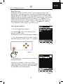
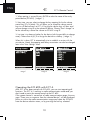
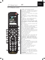
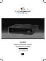
ECI 6DS
Balanced Integrated Amplifier
(with integrated DAC and Streamer)
Owner's Manual
EN
ENGLISH
ENG
Unpacking the ECI 6DS
Immediately upon receipt of the ECI 6DS, inspect the carton for
possible damage during shipment. The carton and packaging have been
designed to provide the safest possible protection for transport of your
integrated amplifier. Unpack the unit carefully. Save all packaging
materials for future shipment.
The contents of the carton
•
•
•
•
•
•
•
1
1
1
1
1
1
2
pc. Electrocompaniet ECI 6DS integrated amplifier.
pc. AC main cord.
pc. Spare main fuse (located in the fuse drawer).
pc. Inspection card.
pc. ECT 4 remote control with a charging docking station and USB cable.
pc. IR Remote control
pcs. Batteries
Set up procedure
Before connecting the ECI 6DS to the AC Power outlet, check that the
main voltage indicated on the rear panel corresponds to the line voltage
in the country were you intend to use the unit.
How to avoid damages
Do not under any circumstances connect or disconnect equipment when
power is turned on. The design of the RCA plug generates a huge transient when inserted. Connecting or disconnecting equipment with the
power on can result in severe damage to both speakers and amplifier.
How to avoid noise problems
The ECI 6DS contains delicate circuits that are sensitive to magnetic
stray fields. The unit should not be placed near power voltage transformers, TV sets etc. Care should also be taken regarding placement of the
interconnect cables. Do not run interconnect cables in parallel with main
cords or speaker cables. Keep interconnect cables as short as possible.
How to avoid possible antenna problems
In some set-ups hum may occur when you connect the radio, VCR or TV
to your system. The problem is caused by DC voltage coming from your
antenna. Please contact your cable network operator.
2
ENG
How to connect your system
Please read this page carefully and follow, page 20-21 as reference.
Balanced XLR input and operation
The balanced mode can only be used if the signal source has a
balanced output. Use an XLR interconnect with GND on pin 1, + on
pin2, and - on pin 3. To use the balanced input with a source single
ended, connect the ECP5XLR in the XLR
Single ended RCA input and operation:
The left channel is the top row on the rear, marked black. All inputs are
similar regarding sonic performance. Unused inputs may be shorted to
ground, using a RCA shorting plug.
HT (Home Theatre)
HT is a direct input where the volume control is bypassed. ECI 6DS will
work like a power amplifier with fixed gain. When selected the output
will be muted for a few seconds as a safety against accidental overload.
Preamp out:
The preamp out is dependent on the volume control setting, and MUTE
function. These outputs (balanced and single ended) can be used to control an additional power amplifier.
Speaker output:
Never short the positive output to ground or chassis. Switch the amplifier
off when connecting the speakers.
How to power up your system
You should always power up your system the following way:
Signal sources (CD player, tuner etc.) first. Allow a 30 seconds warm-up
before you turn on the ECI 6DS.
When switching off your system
Start with the ECI 6DS, then the signal sources. If the preamplifier output
is connected to a power amplifier, then turn off the power before or at
the same time as ECI 6DS.
3
ENG
How to connect your system
Please read this page carefully and follow, page 20-21.
SPDIF inputs
ECI 6DS will accept optical SPDIF sources up to 96 kHz/24bit on inputs
TOSLink1 and TOSLink2. Please use a optical TOSLink cable for this
connection. Connect coaxial sources up to 192kHz/24bit to inputs
COAX1 and COAX2. Please use a coaxial SPDIF cable for this
connection.
12V trigger Input/Output
The 12V trigger output may be used to automatically power up a
CD-player (or other equipment with 12V trigger input) when ECI 6DS is
powered up. When ECI 6DS powers up the 12V trigger output will be
set to 12V and will support up to 75 mA current output. Please keep the
current draw below 75 mA by limiting the number of devices connected
to the 12V trigger output.
The ECI 6DS will power up (leave standby) when a voltage in range
8-20V (AC or DC) is present on the 12V trigger input, and stays powered on for as long as the voltage is present. The current draw at the
12V trigger input is 3.3mA.
RS-232 Control Port
The RS-232 control port may be used in home installation setups or general
usage for controlling basic functionality on the ECI 6DS. Please refer
to document "ECI6DS RS232 Command Reference V1.pdf" for further information. This document may be downloaded from www.electrocompaniet.no
4
ENG
Navigator window
Audio
Source
Display
Text
Description
CD
CD
Analog balanced XLR input
AUX
AUX
Analog single-ended RCA input
DVD
DVD
Analog single-ended RCA input
HT
HT
Analog single-ended home theater RCA input
COAX 1
COAX1
Coaxial S/PDIF input up to 192 kHz/24 bit
COAX 2
COAX2
Coaxial S/PDIF input up to 192 kHz/24 bit
TosLink 1
TOSLNK1
Optical S/PDIF input up to 96 kHz/24 bit
TosLink 2
TOSLNK2
Optical S/PDIF input up to 96 kHz/24 bit
USB
USB
Asynchronous High Speed USB 2.0 input up to
192kHz/24bit
Front panel (see illustration, page 18)
The main switch is located in the center of the lower part of the front
panel. In daily operation, switch off the ECI 6DS by using the STANDBY
button on the remote control. If the ECI 6DS has been switched off, allow
two hours of warm-up for optimal sonic performance. When the ECI 6DS
is not to be used for a long period of time, use the main switch to turn the
unit off. Then disconnect the AC main cord for maximum safety.
Navigator
Button
Function
Description
UP
Volume Up
Increases the volume level.
DOWN
Volume Down
Decreases the volume level.
LEFT
Select source left
Selects the next source to the left.
RIGHT
Select source right
Selects the next source to the right.
5
ENG
Error codes
If the ECI 6DS is not working properly, the display will show an error code.
The error codes are:
Display Error
text
DC FAULT LEFT
DC FAULT
RIGHT
DC
Description
DC voltage left channel
Please contact service center.
DC voltage right
channel
DC left + right channels
OVERLOAD
FAULT
LEFT
Overload of left
channel
OVERLOAD
FAULT
RIGHT
Overload right channel
OVRLOAD
Overload left+right channels
TEMPERATURE
What to do
Over temperature
left+right channel
Make sure that the + and – leads
of the loudspeaker cables are
not shorted, and that the speaker
cables are not in contact with the
chassis of ECI 6DS.
The amplifier is overheated. This is
caused by either playing to loud
for a long period of time, or not
enough free space on the sides or
above the ECI 6DS.
Turn down the volume and make
sure there is enough free space
around the amplifier.
For troubleshooting please contact your local dealer or our support department. All contact information you will find at www.electrocompaniet.no
6
ENG
Replacing a blown main fuse
The main fuse is located in a small drawer inside the AC inlet of the unit.
If, for some reason the fuse is blown, turn the unit off, and remove the
AC cord from the AC inlet. Open the drawer with a small screwdriver
and remove the blown fuse. The spare fuse is located inside a holder in
front of the main fuse.
1.
2.
3.
4.
Remove the spare fuse gently by pushing it sideways out of its holder.
Insert the spare fuse as the active fuse.
Push the drawer gently back to closed position.
Re-insert the AC cord and turn the unit on.
Never replace the fuse with another value than indicated on the unit!
Input configurations
XLR input: 1 = ground 2 = positive 3 = negative
RCA: Center = positive Circle = ground.
Output configurations
XLR output: 1 = ground 2 = positive 3 = negative
Speaker: Red = positive Black or White = ground
ECP5XLR:
RCA to XLR adapter: 1 & 3; ground and negative = shorted 2 = positive
Updating the ECI 6DS firmware
Please download the update instruction from our website at: "Downloads Firmware" area.
7
ENG
ECT 4 Remote Control
Universal Remote Control ECT 4
Unpacking the ECT 4 Remote Control
Immediately upon receipt of the ECT 4, inspect the carton for possible damage during shipment. The carton and packaging have been designed to
provide the safest possible protection for transport of your remote control.
Unpack the unit carefully. Save all packaging materials for future shipment.
The contents of the carton
•
•
•
•
1
1
1
1
pc.
pc.
pc.
pc.
ECT 4 Remote control.
Charging docking station.
USB cable.
Power supply for charging docking station.
Set up procedure
Before use, charge the ECT 4 at least 2 hours.
Charging from the mains
1. Connect the USB cable to the power supply unit and docking station.
2. Place the ECT 4 Remote control in the docking station.
Charging from mini USB
1. Connect the USB cable to a computer or to power supply unit directly.
2. Connect the mini USB plug to ECT 4.
Battery status indicator
The battery status indicator shows the current charge status of the battery
as well as an indication if the remote is currently connected to power and
whether it is charging or not.
Battery full, remote connected to power but not charging
Battery nearly full, remote connected to power and charging
Battery empty, remote not connected to power
8
ENG
ECT 4 Remote Control
Start Pairing
To be able to use the ECI 6DS with ECT 4 the two devices have to be
paired once. In the pairing process the devices exchange some necessary
data like device ID, RF address, etc. After pairing success, ECI 6DS will be
added to the device selection screen of the ECT 4 and can be used. Pairing
mode has to be started on both ECI 6DS and ECT 4. In addition, ECT 4
and ECI 6DS have to be in close proximity to each other. Pairing can be
canceled by pressing “Go back”, “Stop” or “Navigate left”. Hotkeys,
“Zone selection” and “System” key work as well.
Pairing procedure
1. To start the pairing procedure:
Press button
, select "Start pairing" and
press the "Enter" button.
The following screen will be displayed (image 1)
2. Turn on the main switch of ECI 6DS immediately after pressing "Enter" on ECT 4. (image 2)
image 1
image 2
3. When pairing is successful, set the name of
the device found.
If there is no response in time, you will be
informed (image 3) and can try the pairing procedure again. Turn of the ECI 6DS and repeat
the procedure from the beginning.
image 3
9
ENG
ECT 4 Remote Control
1. When pairing is successful press ENTER to select the name of the newly
paired device (ECI 6DS). ( image 1 )
2. Next step, you can select to change the key mapping for the the volume
control keys (V+/V-/Mute). This will allow you to remap the volume control
keys to a IR device known to ECT 4. Pressing the volume keys will then send
volume changes using IR to the selected IR device. Choose "Don't change" to
let the volume keys control the volume on ECI 6DS using RF.
3. Last step is to choose a hotkey for the device (with the possibility to change
zone). Choose from A,B,C,D to assign the device to a Hotkey. ( image 3 )
When this is done, ECT 4 automatically tries to establish a session with the
new device. Name, keymapping and hotkey association can also be changed
later in the "User Settings" menu.
A
image 1 image 2 B
C
D
image 3
Operating the ECI 6DS with ECT 4.
After ECT 4 has been paired with ECI 6DS, you can start operating all
functions. The ECT 4 is working in radio communication mode and you
don't need to point the remote control at the ECI 6DS.
If the remote control is moved out of radio communication range, the message "There was no response from the selected device" will be displayed.
Return to within the radio communication range and select the ECI 6DS
from the device selection menu, or by pressing the hot key selected.
10
ENG
ECT 4 Remote Control
ECT 4 Remote control
1. Standby - switches ECI 6DS on and off.
2. Four hot keys - controlling the devices shown at
the display above each button. ECI 6DS,TV,DVD etc.
3. No function with ECI 6DS.
4. Zone selection - select between zones (Living
room, kitchen etc.)
5. Navigate up - a menu list navigator and also
browses alphanumeric characters, when renaming
devices etc.
6. Settings button - opens the ECT 4 settings menu.
7. Navigate right - similar to ENTER/OK.
8. Add to favourites. Favourite radio station or track.
9. Navigate down - a menu list navigator and also
browses alphanumeric characters, when renaming
the devices etc.
10. Show favourites. Show the list of favourite radio
stations or audio tracks.
11. Plus - used for page wise navigation. Previous track
or previous radio station during music playback.
12. Minus - used for page wise navigation. Next track
or next radio station during music playback.
13. Next track. Hold for fast forward. Goes forward
a track or radio station during browsing other menu
lists or while listening the music.
14. Pause - pauses the music.
15. Stop - Stops the music.
16. Numeric keypad - enters a track number. Also
enters alphanumeric data for renaming devices etc.
17. Repeat button - toggle repeat the track mode.
18. Shuffle button - toggle shuffle mode during music
playback. Changes the character set during alphanumeric entry.
19. No function with ECI 6DS.
20. Previous track - Hold for fast rewind. Goes backward a track or radio station during browsing other
menu lists or while listening the music.
21. Play - plays the selected track.
22. Volume down - decreases the volume level.
23. Volume up - increases the volume level.
24. Mute - mutes the sound.
25. (Context) Menu.
26. Back button - moves back to a previous menu.
27. Navigate left - may work the same as "Back" button
28. Information button - additional information about
the track playing.
29. ENTER/OK - confirm selected menu.
30. Home - the Home Menu button, source selection.
11
ENG
ECT 4 Remote Control
Operating the ECT 4
When music is playing, the display shows information about the
track playing, the time and settings.
5
6
1
7
2
3
4
10:30 ECI 6DS
8
9
Vol: 56
1). Album cover or radio
station logo will appear here,
if available.
2). Information about music
(when available).
3). Indicator for play/pause and
elapsed track time/total time.
4). Clock and controlled device
5). Battery indicator.
6). Indicator for repeat function
7). Indicator for shuffle function
8). Track bit rate.
9). Volume level
Power control and home screen
Press the
button to switch the ECI 6DS on, press again for
Standby mode. When the ECI 6DS is powered on, the source menu
screen with all available sources will be displayed.
The following choices are available:
1. Internet Radio
2. Audio Server - play the music from any
available network server.
3. Memory Stick - plays music from a memory stick.
4. COAX 1 - SPDIF COAX 1 input.
5. COAX 2 - SPDIF COAX 2 input.
6. TOSLink 1 - SPDIF TOSLink input.
7. TOSLink 2 - SPDIF TOSLink input.
8. USB - USB input.
9. CD - CD input.
10. AUX - AUX input.
11. DVD - DVD input.
12. HT - Home Theater input.
13. Receiver settings - set up the network setting,
IP address, MAC address, network device name, remote access...
12
ENG
ECT 4 Remote Control
How to connect to Network and Internet
Wired LAN Connection
Connect the Ethernet cable to the LAN port at the back panel of ECI 6DS.
When turned on, the ECI 6DS will try to establish connection automatically using DHCP. It is also possible to set network options manually. Go to
the "Home" menu, scroll to the bottom of the source list, select "Receiver
"Settings" and then "Network".
Wireless connection (Wi-Fi)
To establish the wireless connection please
follow the following steps.
1. Connect the Wi-Fi antenna to the ECI 6DS.
2. Turn on the ECI 6DS.
3. When Home menu is displayed, go to
"Receiver settings" -> "Network" -> "Change
settings".
4. Select the Wi-Fi network from the list or
press "Rescan" if network list is not available. Enter the password for your Wi-Fi
network using the alphanumeric buttons.
Press the Shuffle button to change the
character set. Press the Up/Down buttons to
scroll trough the alphabet. Press the Left button to delete a letter. After a
password is entered, press the Enter button.
Play music from your network
1. Select "Audio server" from the Home menu.
2. Select the audio server you want from the list.
3. Choose the music by Artist, Album, Title or
other options displayed.
4. Press the button "Play" or "Enter" when a
wanted track is highlighted.
5. After a small delay the current playing
music will appear on the display. Use the
"play", "stop"," "forward", "back" and
"pause" buttons to control the music playback. Use the "Volume +" and "Volume -" to
adjust the volume level.
13
ENG
ECT 4 Remote Control
Play music from a Memory stick
1. Connect your memory stick to the USB port at
the rear panel ( image 1).
2. Select "Memory Stick" from the "Home" menu.
3. Choose the music by Artist, Album, Title or
other options displayed.
4. Press the button "Play" or "Enter" when a
wanted track is highlighted.
5. After a small delay the current playing
music will appear on the display. Use the
"play", "stop"," "forward", "back" and
"pause" buttons to control the music playback.
Use the "Volume +" and "Volume -"
to adjust the volume level.
14
USB port
image 1
ENG
ECT 4 Remote Control
Settings menu
Press the "Settings" button to open the system
settings menu. Under this menu there is five
submenus:
1. Device selection 2. Change Zone
3. System Information 4. User-Settings
5. Start Pairing
User settings menu
Under the User settings menu you will find
the following settings:
Name - select and press Enter, to change the
name of the remote control.
Time - select and press Enter, to change the time.
Standby - select and press Enter, to change time for the backlight delay.
Time in cradle - turn on the clock as screen saver when remote is standing
charging in a cradle.
Brightness - select and press Enter, to change the brightness of the display.
There is three options: Fixed 1- Darkest, Fixed 3 - brightest and Fixed 2 is
automatic, the light sensor will set the brightness.
HKEY configuration - Choose and assign controllable devices to four Hotkeys located under the display.
Key mapping - select and press Enter, to set or reset the key mapping for
controllable devices.
Change language - select and press Enter, to change the language.
Choose from available languages an press Enter to confirm.
Rename device - select and press Enter, to rename the controllable device.
Delete device - select and press Enter, to delete the device from remote.
Add zone - select and press Enter, to create a new zone.
Rename zone - select and press Enter, to rename existing zones.
Delete zone - select and press Enter, to delete existing zones.
Transportation lock - select and press Enter, to disable the motion sensor.
15
ENG
Updating software and programming the ECT 4
ECT 4 is a universal remote control that also are able to control other IR
devices. To setup, please download and install the "Remote Configtool"
program. The installation file is available on our website at the
"Downloads - Firmware" area. Once the configuration program is installed
please follow the following steps:
image 1
1. Connect your ECT 4 to a PC or laptop
using the USB cable. Don't use the docking
TV
ECI 6
station. The docking station is only for charging the battery.
2. Once connected, press the "Settings" button
and select "System information".
3. Press the "red" button ( image 1). You will
see the message "Connecting, Please wait!".
1
23
When the message is changed to "Connected.
Please proceed." Go to the next step.
4. Start the "Remote configtool" program and
press the button "Connect".
5. The main menu screen will be displayed. Please select the "brand" and
"Type" of IR device which you would like to add and press the Ok button.
6. Now you are able to program the buttons. The buttons marked with a
green color is automatically assigned buttons. You can also program any
buttons which to highlighted.
7. Press the "Add device" button.
8. Enter the name of the new device.
9. After you have added all devices , press the "write info" button.
10. Press the "Send to remote" button to complete the programming.
11. The message "Data successfully transmitted" will be displayed and the
remote control will re-boot automatically.
12. Now you can find your newly added device under the "Device"
selection menu.
Updating the ECT 4 firmware
1. For updating the firmware please follow the steps 1-4 from the "Remote
Configtool program" above.
2. Press the button "Update". The information about current firmware
and new firmware will be displayed. Press the "Start update" button for
upgrading the firmware.
16
ENG
Technical specifications ECI 6DS:
The following technical data were measured on randomized test objects
and are typical data. All measurements are made at 120V / 240V //
50Hz / 60Hz. Clipping point of the amplifier is set to a level where
total harmonic distortion (THD) is 0.2 %.
Preamplifier section
Input impedance(Balanced input)....................................... 47 kOhm
Noise floor (1Vrms, 20 - 20 kHz, balanced)....................... < -135 dB
THD + N (1Vrms, 20 - 20 kHz, balanced) ......................... <0,003%
Gain (Balanced)................................................................... ...0 dB
Amplifier section
Output Impedance ........................................................< 0,02 Ohm
Frequency response (- 3 dB)............................................1 – 150 kHz
Channel separation........................................................> 120 dB
THD + N (20 - 20 kHz).................................................< 0,004%
Maximum peak current...................................................>100A
Damping factor (8 ohm load)..........................................>350
Input sensitivity (125W output)......................................1.3Vrms
Input sensitivity HT (125W output)....................................1Vrms
Gain HT (input)..............................................................31dB (x36)
SPDIF inputs.................................................. 2 x Coax, 2 x TOSLink
USB......................................................................1x 192kHz/24bit
Rated output power
10 % change in line voltage will give approximately 20 % change in
output power.
8 Ohm..........................................................................2 x 125 W
4 Ohm..........................................................................2 x 200 W
2 Ohm..........................................................................2 x 370 W
Power consumption (no load or signal)...................................110 W
Standby....................................................................................1W
Dimensions
Width: 483 mm - 19 inch
Depth: 405 mm - 16 inch
Height: 135 mm - 5,3 inch
Weight: 20 Kg - 44 lbs
*Specifications are subject to change without further notice.
17
ENG
ECI 6DS Front panel illustration
18
1. Optical digital input, TOSLink 1
2. RS 232 connection
3. USB audio input
4. Coaxial digital input 1
5. 12 V trigger input
6. Coaxial digital input 2
7. 12 V trigger output
8. Optical digital input 2, TOSLink 2
9. Balanced analog right CD input
10. Balanced analog left CD input
11. DVD analog inputs
12.
13.
14.
15.
16.
17.
18.
19.
20.
21.
22.
AUX analog inputs
Home theater analog inputs
Pre-amplifier analog output
Pre-amplifier Balanced analog right output
Pre-amplifier Balanced analog left output
Serial number
AC Power Inlet
USB port
Ethernet connection
WLAN antenna connector
Speaker outputs
ENG
ECI 6DS Rear panel illustration
19
20
INPUT
IN
OUT
TRIGGER
COAX 1 COAX 2 TOSLINK
DIGITAL
CD player
RS-232
USB
USB
LAN
CD-R
DVD / Blu-ray player
CD-L
DVD
ANALOG INPUT
AUX
HT
WLAN
RIGHT
PREAMP OUT
LEFT
TYPE : ECI 6
Made in Norway
Manufactured by:
Electrocompaniet
Norway
RIGHT
SPEAKER OUTPUT
LEFT
AV-Receiver
ENG
How to connect the system (Analog Inputs)
Media Player
21
RS-232
USB
INPUT
IN
OUT
TRIGGER
COAX 1 COAX 2 TOSLINK 2
DIGITAL
LAN
CD-R
CD-L
DVD
ANALOG INPUT
Ethernet Hub
Gaming console
TOSLINK 1
USB
Memory Stick
AUX
RIGHT
LEFT
TYPE : ECI 6
Made in Norway
PREAMP OUT
PC / MAC
HT
WLAN
Manufactured by:
Electrocompaniet
Norway
RIGHT
SPEAKER OUTPUT
LEFT
ENG
How to connect the system (Digital Inputs)
ENG
Important Notice
For optimal sonic performance, the ECI 6DS should be burned in for a
minimum time of 72 hours. The easiest way to burn in your ECI 6DS is
to put a signal at any input, without the speakers connected In daily
operation, switch off the ECI 6DS by using the MUTE button on the
remote control. If the ECI 6DS has been switched off, allow two hours of
warm-up to optimal sonic performance. Due to high class A operation in
all Electrocompaniet designs, it is normal for the ECI 6DS to feel warm.
Proper ventilation is important. It is important that there is at least 3-5 cm
(1-2inches) of air on the left side of the amplifier and 5-8 cm (2-3 inches)
above. Never cover the ventilation area.
If Service is needed
Your dealer will have all relevant information regarding the service centers in your area, and will ensure that your unit is serviced with minimum
delay. It is our general policy to have your unit returned to you within
five working days. This is an average time, and can vary locally,
depending on the workload at that particular service station. If, for some
reason, there are no service facilities available in your country, please
ship the unit to the following address:
Electrocompaniet AS,
Breivikveien 7,
N-4120 Tau,
Norway
Web: www.electrocompaniet.com
The end user is responsible for all shipping charges, insurance, re-importation and duty charges. When shipping a product to the factory for
service, always include the following:
1. A sales slip or other proof of purchase if repair is claimed under warranty.
2. A proforma invoice with value of goods, stating that the amplifier is
returned to Norway for repair.
3. An accompanying letter describing faults, symptoms, or problems with
the unit.
4. Always ship the unit in its original carton and packaging material to
prevent damage in transit.
Electrocompaniet will not cover damages incurred in transit. If you
require further information concerning the operation of the unit, or if you
have any questions related to service, please do not hesitate to contact
your dealer or your national distributor.
22
ENG
23
ENG
DEALER
Sticker
HERE
LOCAL DEALER
Warning!
To avoid risk of fire or electric shock, do not expose this appliance to rain or moisture.
Verify line voltage before use.
Do not remove cover. No user serviceable parts inside.
Refer servicing to qualified service personal.
The warranty is void if the product is tampered with by non-authorised personnel.
Use only authorized Electrocompaniet service center.
Made in Norway
www.electrocompaniet.no
24