1
XM / XP SERIES
Uninterruptible Power Supplies
XM 6005 Series
XM 6007 Series
XM 6010 Series
XM 6012 Series
XM 6015 Series
Technical Manual
©1997 Alpha Technologies
017-039-B0-006 06/99
IMPORTANT SAFETY INSTRUCTIONS
CONTAINED IN THIS MANUAL
CAUTION
RISK OF ELECTRICAL SHOCK
CAUTION: TO REDUCE THE RISK OF ELECTRICAL
SHOCK, AND ENSURE THE SAFE OPERATION OF THIS
UNIT, THE FOLLOWING SYMBOLS HAVE BEEN PLACED
THROUGHOUT THE MANUAL. WHERE THESE SYMBOLS
APPEAR, SERVICING SHOULD BE PERFORMED ONLY BY
QUALIFIED PERSONNEL.
DANGEROUS VOLTAGE
A DANGEROUS VOLTAGE EXISTS IN THIS AREA OF THE
POWER SUPPLY. USE EXTREME CAUTION.
ATTENTION
IMPORTANT OPERATING INSTRUCTIONS. THIS PROCEDURE SHOULD BE PERFORMED ONLY BY QUALIFIED
SERVICE PERSONNEL.
SAVE THESE INSTRUCTIONS
IMPORTANT TECHNICAL NOTE
CAUTION:
When operating the XP Series Uninterruptible Power Supply,
a minimum load of at least 1.0 Amperes (approximately 10%
of the output rating of the power supply) must be connected to the output.
Failure to do so could damage the load or the unit’s ferroresonant power
transformer.
Damage caused by this condition will not be covered under warranty.
For further information, contact Alpha Technologies or your nearest
Alpha representative.
IMPORTANT SAFETY PRECAUTIONS
THE POWER SUPPLY SHOULD BE SERVICED ONLY BY QUALIFIED PERSONNEL.
THE POWER SUPPLY CONTAINS MORE THAN ONE LIVE CIRCUIT. EVEN THOUGH AC
IS NOT PRESENT AT THE INPUT, IT MAY BE PRESENT AT THE OUTPUT.
WHEN USING AN EXTERNAL SERVICE DISCONNECT, VERIFY THAT IT IS EQUIPPED
WITH A HIGH MAGNETIC CIRCUIT BREAKER PROPERLY RATED (AMPERAGE) FOR
USE WITH THE POWER SUPPLY.
WHEN IN STORAGE, BATTERIES SHOULD BE CHARGED AT LEAST ONCE EVERY
THREE MONTHS TO ENSURE OPTIMUM PERFORMANCE AND BATTERY LIFE.
WEAR EYE PROTECTION, SUCH AS SAFETY GLASSES OR A FACE SHIELD, WHENEVER WORKING WITH BATTERIES.
USE GLOVES WHEN HANDLING BATTERIES. BATTERY ELECTROLYTE IS ACIDIC AND
MAY CAUSE BURNS.
NEVER SMOKE NEAR BATTERIES. SPARKS, FLAMES OR OTHER SOURCES OF
IGNITION MAY CAUSE A BATTERY EXPLOSION.
ALWAYS CARRY A SUPPLY OF WATER, SUCH AS A WATER JUG, TO WASH THE EYES
OR SKIN IN THE EVENT OF EXPOSURE TO BATTERY ELECTROLYTE.
USE PROPER LIFTING TECHNIQUES WHENEVER HANDLING THE ENCLOSURE, POWER
MODULE OR BATTERIES. GROUP 31 SIZE BATTERIES, USED IN THE MAJORITY OF
CABLE TELEVISION APPLICATIONS, CAN WEIGH AS MUCH AS 70 LBS.
USE A BUCKET TRUCK, OR SUITABLE SAFETY EQUIPMENT SUCH AS A SAFETY
HARNESS AND CLIMBING SPIKES, WHEN SERVICING POLE INSTALLATIONS.
ALWAYS SWITCH THE POWER SUPPLY’S BATTERY CIRCUIT BREAKER TO OFF
BEFORE DISCONNECTING BATTERY CABLES. THIS GREATLY REDUCES THE CHANCE
OF SPARK AND POSSIBLE BATTERY EXPLOSION.
DO NOT ALLOW LIVE BATTERY WIRES TO CONTACT THE ENCLOSURE OR POWER
SUPPLY CHASSIS. POSSIBLE EXPLOSION OR FIRE CAN OCCUR.
BEFORE PLACING A CURRENT LOAD ON THE BATTERIES, (SUCH AS WHEN SWITCHING THE POWER SUPPLY TO STANDBY), USE THE ENCLOSURE DOOR AS A SHIELD
IN THE EVENT OF A BATTERY EXPLOSION.
INSPECT BATTERIES FOR SIGNS OF CRACKS, LEAKING OR SWELLING.
WHEN REPLACING BATTERIES, ALWAYS USE THOSE OF AN IDENTICAL TYPE.
NEVER INSTALL OLD OR UNTESTED BATTERIES.
CHECK THE BATTERY’S DATE CODE. BATTERIES OLDER THAN SEVERAL YEARS
SHOULD NOT BE USED.
AVOID THE USE OF UNINSULATED TOOLS OR OTHER CONDUCTIVE MATERIALS
WHEN HANDLING BATTERIES OR WORKING INSIDE THE ENCLOSURE.
SPENT OR DAMAGED BATTERIES ARE CONSIDERED ENVIRONMENTALLY UNSAFE.
ALWAYS RECYCLE USED BATTERIES.
BATTERY CHARGING
ALWAYS REFER TO THE BATTERY MANUFACTURER’S RECOMMENDATION FOR
SELECTING CORRECT FLOAT AND EQUALIZE CHARGE VOLTAGES. FAILURE TO DO
SO COULD DAMAGE THE BATTERIES.
VERIFY THE POWER SUPPLY’S BATTERY CHARGER FLOAT AND EQUALIZE CHARGE
VOLTAGES. REFER TO THE POWER SUPPLY’S OPERATION MANUAL.
BATTERIES ARE TEMPERATURE SENSITIVE. DURING EXTREMELY COLD CONDITIONS, A BATTERY’S CHARGE ACCEPTANCE IS REDUCED AND REQUIRES A HIGHER
CHARGE VOLTAGE; DURING EXTREMELY HOT CONDITIONS, A BATTERY’S CHARGE
ACCEPTANCE IS INCREASED AND REQUIRES A LOWER CHARGE VOLTAGE.
TO COMPENSATE FOR CHANGES IN TEMPERATURE, THE BATTERY CHARGER USED
IN THE POWER SUPPLY IS TEMPERATURE COMPENSATING. FLOAT AND EQUALIZE
CHARGE VOLTAGES WILL VARY DEPENDING UPON BATTERY TEMPERATURE.
IF BATTERIES APPEAR TO BE OVER OR UNDER-CHARGED, FIRST CHECK FOR
DEFECTIVE BATTERIES AND THEN VERIFY CORRECT CHARGER VOLTAGE SETTINGS.
BATTERY PREVENTIVE MAINTENANCE
BATTERIES SHOULD BE INSPECTED EVERY THREE TO SIX MONTHS TO ENSURE
OPTIMUM PERFORMANCE.
VISUALLY INSPECT BATTERIES FOR SIGNS OF CRACKS, LEAKS OR SWELLING.
CHECK BATTERY TERMINALS AND CONNECTING WIRES. BATTERY TERMINAL
CONNECTORS SHOULD BE CLEANED PERIODICALLY AND RETIGHTENED TO APPROXIMATELY 60 INCH/LBS. SPRAY THE TERMINALS WITH AN APPROVED BATTERY
TERMINAL COATING SUCH AS NCP-2.
CHECK BATTERY VOLTAGES UNDER LOAD. USE A LOAD TESTER IF AVAILABLE.
DIFFERENCES BETWEEN ANY BATTERY IN THE SET SHOULD NOT BE GREATER THAN
0.3 VDC.
CHECK THE POWER SUPPLY’S BATTERY CHARGER VOLTAGES. REFER TO THE
BATTERY MANUFACTURER’S RECOMMENDATION FOR CORRECT CHARGE VOLTAGES AND THE POWER SUPPLY’S OPERATION MANUAL FOR CORRESPONDING
CHARGER SETTINGS.
NUMBER THE BATTERIES (1, 2, 3) INSIDE OF THE ENCLOSURE FOR EASY IDENTIFICATION.
ESTABLISH AND MAINTAIN A BATTERY MAINTENANCE LOG.
XP Series Uninterruptible Power Supplies
Table of Contents
1.
INTRODUCTION
1.1
1.2
1.2.1
1.2.2
1.2.3
1.3
2.
The XP Series Uninterruptible Power Supply
Theory of Operation
AC (LINE) Operation
Inverter (STANDBY) Operation
Charger Operation
Specifications
FRONT PANEL
2.1
2.1.1
2.1.2
2.1.3
2.1.4
2.1.5
2.2
2.2.1
2.2.2
2.2.3
2.2.4
2.3
2.3.1
2.3.2
2.3.3
2.4
2.4.1
2.5
2.5.1
2.5.2
2.5.3
2.5.4
3.
1
6
APM (Automatic Performance Monitor) Status Block
"TEST/RESET" Switch
"NOT INSTALLED" LED
"TEST IN PROGRESS" LED
"CHECK BATTERIES" LED
"CHECK INVERTER" LED
Charger Status Block
"CHARGE MODE" Switch
"FLOAT" LED
"EQUALIZE" LED
"RECHARGE" LED
System Status Block
"LINE POWER" LED
"STANDBY POWER" LED
"AC OUTPUT" LED
Output Current Display
LED Display
SDD (Standby Data Display)
"MODE" Switch
"ELAPSED TIME" LED
"STANDBY EVENTS" LED
Time/Events Window
SIDE PANEL
3.1
3.2
3.3
3.4
3.5
3.6
3.7
3.8
3.9
3.10
3.11
12
AC Power Cord
Standby Status Relay (SSR)
Remote Indicator Lamp (LRI)
AC Output
Battery Connector
AC Output Fuse
Battery Circuit Breaker
Main Circuit Module Access Handle
USM Connector Access
Remote Temperature Sensor Connector (RTS)
Data Port
i
Table of Contents, continued
4.
STANDARD FEATURES
4.1
4.2
4.3
4.4
4.5
5.
OPTIONAL FEATURES
5.1
5.2
5.3
5.4
5.5
5.6
5.7
5.8
5.9
5.10
5.11
5.12
5.13
5.14
5.15
5.16
5.17
5.18
5.19
5.20
5.21
5.22
5.23
5.24
5.25
6.
15
XP6005 Series Uninterruptible Power Supplies
XP6007 Series Uninterruptible Power Supplies
XP6010 Series Uninterruptible Power Supplies
XP6012 Series Uninterruptible Power Supplies
XP6015 Series Uninterruptible Power Supplies
16
APM-XP (Automatic Performance Monitor)
USM (Universal Status Monitor)
LRI (Local and Remote Indicator)
ACI (AC Indicator)
SDD (Standby Data Display)
SSR (Standby Status Relay)
LA-P (Lightning Arrestor)
BCK-X (Battery Cable Kit)
BCK-FX (Fused Battery Cable Kit)
BMO (Battery Mat Option)
BTO (Battery Tray Option)
MST (Module Slide Tray)
DSE (Delete Service Entrance)
ISE (Internal Service Entrance)
STH (Storm Hoods)
XPA (XP Adaptor)
APP60S (Service Power Supply)
Batteries
ABC-12 (Battery Charger)
Enclosures
PS Series (Pedestal Supports)
DataLogger
AC Series (Amp Clamps)
CAT-PAK (Computer Aided Training)
Instructional Videotapes
INSTALLATION
6.1
6.2
6.3
6.3.1
6.3.2
6.4
6.5
6.6
6.7
6.8
6.9
6.9.1
6.9.2
6.10
6.10.1
6.10.2
6.11
6.11.1
6.11.2
20
Unpacking and Inspection
Pole-mount Enclosure Installation (PME and PWE)
Ground-mount Enclosure Installation (UPE and UPE/M)
Pedestal Support Preparation
Concrete Pad Preparation
Connecting Utility Power
Connecting the SPI (Service Power Inserter)
Power Module Installation
Battery Installation and Wiring
Main Circuit Module Removal and Installation
Standard Control Logic
Selecting Battery Charge Voltages
Float and Equalize Chart
APM (Automatic Performance Monitor)
"Auto-Test" Interval and Duration Selection
"Auto-Equalize" Interval and Duration Selection
USM (Universal Status Monitor)
Parallel Configurations
Serial Configuration
ii
Table of Contents, continued
7.
37
OPERATION
7.1
XM Power Module Start-up and Testing
7.1.1
AC Line Operation (LINE POWER)
7.1.2
Inverter Operation (STANDBY)
7.2
Identifying Modes of Operation
7.2.1
System Status Block
7.2.1.1
AC LINE Operation
7.2.1.2
STANDBY Operation
7.2.1.3
TRANSFER or SELF-TEST Mode
7.2.2
Charger Status Block
7.2.2.1
FLOAT Mode
7.2.2.2
EQUALIZE Mode
7.2.2.3
RECHARGE Mode
7.2.3
APM (Automatic Performance Monitor) Status Block
7.2.3.1
SELF-TEST Mode
7.2.3.2
BATTERY FAILURE
7.2.3.3
INVERTER FAILURE
7.3
Power Module Shutdown
8.
MAINTENANCE
8.1
8.2
8.3
8.4
8.5
8.6
8.7
8.8
8.8.1
8.8.2
8.8.3
8.9
8.10
9.
TROUBLE-SHOOTING AND REPAIR
9.1
9.2
9.3
9.4
10.
51
42
Check Battery Terminals and Connecting Wires
Check Battery Open Circuit Voltage
Check Battery Voltage Under Load
Check Battery Charger (FLOAT) Voltage
Check Battery Charger (EQUALIZE) Voltage
Check Output Voltage
Check Output Current
APM Manual Self-test
"TEST IN PROGRESS"
"CHECK BATTERIES"
"CHECK INVERTER"
Main Circuit Module and Logic Board Maintenance
Fuse Replacements
Repair Instructions
Parts and Ordering Instructions
Common Parts for XP Series Uninterruptible Power Supplies
Trouble-shooting Guide
WARRANTY
iii
46
Table of Contents, continued
ILLUSTRATIONS (contained in the manual)
XM Series Front Panel
APM Status Block
Charger Status Block
System Status Block
Output Current Display
Standby Data Display
XM Series Side Panel
PME and PWE Enclosures
UPE and UPE/M Enclosures
120 VAC and 220 or 240 VAC Input Circuit Breaker Assemblies
SPI (Service Power Inserter)
Module Installation and Wiring Diagram
Battery Date Code Identification, Numbering and RTS Placement
ABC-12 Battery Charger
Main Circuit Module Assembly
APM Logic Card
USM Logic Card
USM Configuration Diagrams
USM/AlphaSoft Block Diagram
Indentifying Modes of Operation
APP60S (Service Power Supply)
DataLogger
DRAWINGS (located at the back of the manual)
PME Pole-mount Enclosure Installation and Wiring (UL / CSA)
PWE Pole-mount Enclosure Installation and Wiring (UL / CSA)
Pedestal Support for UPE Ground-mount Enclosures
Concrete Pad for UPE Ground-mount Enclosures
Pedestal Support for UPE/M Ground-mount Enclosures
Concrete Pad for UPE/M Ground-mount Enclosures
XM Series Power Module in PME Enclosure
XM Series Power Module in PWE Enclosure
XM Series Power Module in UPE Enclosure
XM Series Power Module in UPE/M Enclosure
Battery Wiring with Remote Battery Temperature Sensor Connection
SPI / Output Filter Installation
ACI / LRI Options for PME and PWE Enclosures
XM Series Side Panel
XM Series Power Module Block Diagram
XM Series Component Layout
iv
1. INTRODUCTION
INTRODUCTION
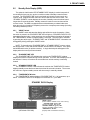
1.1
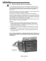
THE XP SERIES UNINTERRUPTIBLE POWER SUPPLY
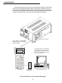
Alpha XP Series Uninterruptible Power Supplies (UPS) are designed for powering
signal processing equipment in Cable Television and Broadband LAN distribution systems.
The power supply, which consists of an XM Series Power Module and a pole or groundmount enclosure, provides the critical load with current-limited, regulated AC power that is
free from disturbances such as spikes, surges, brownouts or blackouts. Backup power is
achieved by a set of rechargeable, gelled electrolyte (no maintenance) batteries.
During LINE operation, AC power enters the module where it is converted to a "quasi"
square wave and regulated (at the required output voltage). It is then passed onto the load
via the SPI (Service Power Inserter) located inside the power supply enclosure. At the
same time, power is directed to the battery charger to maintain a float charge to the
batteries.
When the incoming AC line voltage drops significantly, or a utility power outage
occurs, the XM Series power module automatically transfers to inverter (STANDBY)
operation in order to maintain power to the load. During the transfer, energy contained in
the module's ferroresonant transformer continues to supply power to the output. Depending
upon the type of batteries used, and the loading on the power supply, backup power can
continue for several hours. When utility line power returns, the XM Series power module
waits momentarily for the utility voltage and frequency to stabilize and then initiates a
smooth, in-phase transfer back to AC line power. Once the transfer is complete, the
battery charger quickly recharges the batteries in preparation for the next utility power
outage.
The XP Series Uninterruptible Power Supply contains an impressive list of features
including an "OUTPUT CURRENT" display to indicate output current to the load; a
"CHARGER STATUS" block to display the various battery charging modes; a "SYSTEM
STATUS" block to display LINE and STANDBY operation, plus indicate acceptable AC
output power; an output fuse to protect against excessive short circuit currents; and a
battery circuit breaker to protect the DC circuit. Optional features can include a
"STANDBY DATA" display to indicate "total outage time" and "number of standby events;"
an APM (Automatic Performance Monitor) to self-test the inverter and batteries at regular
intervals; and a USM (Universal Status Monitor) plug-in logic upgrade to facilitate status
monitoring.
UL Recognized and CSA Approved, the XP Series Uninterruptible Power Supply is
designed to be one of the most rugged, reliable, and versatile power supplies available.
Alpha Technologies, recognized as an international market leader in the field of backup
power, offers complete technical support and prompt, reliable service to ensure that your
power supply continues to provide years of trouble-free operation.
1
1. INTRODUCTION
1.2
Theory of Operation
The XP Series Uninterruptible Power Supply consists of an XM Series power module,
a pole or ground-mount enclosure, and a set of gelled electrolyte, no maintenance batteries. The power module contains a ferroresonant transformer, resonant capacitor, dualmode temperature-compensated battery charger, DC to AC converter (inverter), transfer /
isolation relay, and a main circuit module assembly containing the logic circuit.
The XP Series Uninterruptible Power Supply
1.2.1 AC (LINE) Operation
During AC LINE operation, utility power is routed into the primary winding of
ferroresonant transformer T1 and through the contacts of the transfer / isolation relay K101.
At the same time, power is directed to the auxiliary transformer T101 which provides power
for the control circuitry. A charger / inverter winding on transformer T1 supplies the battery
charger circuit. AC capacitor C1 forms the resonant circuit of ferroresonant transformer T1
which provides excellent noise and spike attenuation, short circuit current limiting, and
output voltage regulation. The ferroresonant transformer produces a "quasi" square wave
output which resembles a rounded square wave.
NOTE: WHEN MEASURING THE OUTPUT VOLTAGE OF FERRORESONANT
TRANSFORMERS, USE ONLY A TRUE RMS AC VOLTMETER. NON-RMS READING
METERS ARE CALIBRATED TO RESPOND TO PURE SINE WAVES AND WILL NOT
PROVIDE AN ACCURATE READING WHEN MEASURING A "QUASI" SQUARE WAVE
OUTPUT.
2
1. INTRODUCTION
1.2
Theory of Operation, continued
1.2.2 Inverter (STANDBY) Operation
When the incoming AC line voltage drops significantly, or a complete power outage
occurs, the control logic’s line monitor activates STANDBY operation. The battery powered inverter comes on-line (in-phase with the failing AC line) as the transfer / isolation
relay switches to prevent AC power from back-feeding to the utility. During the brief
transfer from LINE to STANDBY operation, the energy contained in the ferro-resonant
transformer continues to supply power to the load. The following changes occur: The
transfer / isolation relay K101 opens to disconnect the AC line from the primary winding of
ferroresonant transformer T1. The control logic drives the inverter transistors on and off at
line frequency. This switching action converts the DC battery current into AC in the
inverter winding of the ferroresonant transformer which provides regulated power to the
load. The control logic, which includes a circuit to protect the inverter transistors from
over-current damage, monitors the condition of the batteries during inverter operation.
Since a prolonged AC line outage would severely discharge the batteries, resulting in
permanent damage, the control logic disables the inverter when the batteries drop to
approximately 10.5 VDC / battery (31.5 VDC / set).
When AC line voltage returns, the power module transfers back to LINE operation
within 10 to 50 seconds. This delay allows the AC line voltage and frequency to stabilize
before the control logic phase-locks the inverter’s output to the utility input. It then deenergizes the transfer / isolation relay, re-connects the AC line to the primary of the
ferroresonant transformer and disconnects the batteries from the inverter. This results in a
smooth, in-phase transfer back to utility power without interruption of service to the load.
The battery charging circuit is then activated to recharge the batteries in preparation for the
next power outage.
1.2.3 Charger Operation
The XP Series Uninterruptible Power Supply uses a dual-mode, temperature-compensated battery charger. During AC line operation, a charger / inverter winding on
ferroresonant transformer T1 feeds the charger circuit which provides "float" and "equalize"
charge voltages to the batteries. The circuit consists of a switching regulator, inductor L1
and other associated components. The charger (inverter) winding of transformer T1
produces an AC voltage that is regulated by SCRs Q301, Q302 and filtered by inductor L1.
This produces a regulated DC battery charging voltage. The charge current passes
through R104 to provide current-limit sensing for the charging circuit. Fuse F301, located
on the removable, Main Circuit Module assembly, protects the circuit in the event of
charger malfunction or reversal of the battery leads (Refer to the component layout drawing
at the back of the manual).
The standard control logic provides a constant (programmable) float charge to the
batteries. A switch (CHARGE MODE) SW201 located on the front panel of the power
module allows a technician to manually activate the charger’s equalize mode which has a
1.2 hour duration. With the optional APM or USM logic upgrade installed, the equalize
charging mode becomes an automatic user-programmable function.
When the XM Series module resumes LINE operation, the charger quickly recharges
the batteries. The charge current is determined by the acceptance level of the batteries,
but limited to 10 Amps maximum. As the batteries approach full charge, the charger’s
current tapers off to normal float levels.
The three color-coded LEDs on the XP front panel "CHARGER STATUS" block display
charging modes. When lighted, the LEDs indicate FLOAT (green), EQUALIZE (yellow) and
RECHARGE (red). Recharge represents a charge rate greater than 5 Amps.
3
1. INTRODUCTION
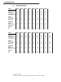
1.3
SPECIFICATIONS
MODEL
XM6005
CONFIGURATION -24 J5
INPUT
Voltage (VAC)
100
Frequency (Hz)
50
Current Max. (A)1
6.7
Low AC Ref. (VAC)
80
XM6005
-24 J6
XM6007
-
XM6007
E
XM6007
P
XM6010
-
XM6010
E
XM6010
P
100
60
6.7
80
120
60
7.2
95
230
50
4
182
220
60
4.2
174
120
60
9
95
230
50
4.7
182
220
60
5
174
OUTPUT
Voltage (VAC)
Current Max. (A)
Power (VA)
60
5.3
320
60
5.3
320
60
7
420
60
7
420
60
7
420
60
10
600
60
10
600
60
10
600
BATTERIES
Number
Voltage (VDC)
Backup Time (Hrs)*
2
24
6
2
24
6
3
36
7
3
36
7
3
36
7
3
36
4.5
3
36
4.5
3
36
4.5
WEIGHTS
(lbs)
(kg)
35
16
35
16
44
19.9
42
19
44
19.9
44
19.9
42
19
44
19.9
XM6012
-
XM6012
E
XM6015
-
XM6015
E
XM6015
-J5
XM6015
-J6
XM6015
MX
XM6015
P
120
60
10
95
230
50
5.5
182
120
60
12
95
230
50
6.7
182
100
50
14
80
100
60
14
80
127
60
12
100
220
60
6.7
174
XM6010
MODEL
-24
CONFIGURATION
INPUT
120
Voltage (VAC)
60
Frequency (Hz)
9
Current Max. (A)1
95
Low AC Ref. (VAC)
OUTPUT
Voltage (VAC)
Current Max. (A)
Power (VA)
60
10
600
60
12
720
60
12
720
60
15
900
60
15
900
60
15
900
60
15
900
60
15
900
60
15
900
BATTERIES
Number
Voltage (VDC)
Backup Time (Hrs)*
2
24
3
3
36
5
3
36
5
3
36
3.1
3
36
3.1
3
36
3.1
3
36
3.1
3
36
3.1
3
36
3.1
44
19.9
34
15.4
40
18.1
55
24.9
63
28.4
63
28.4
55
24.9
55
24.9
55
24.9
WEIGHTS
(lbs)
(kg)
1
At nominal line voltage.
*Note: Battery run times are subject to temperature, age and overall condition of batteries.
4
1. INTRODUCTION
1.3
SPECIFICATIONS, continued
Regulation
Input Voltage (VAC)
Input Frequency (Hz)
Output Voltage (VAC)
Output Frequency (Hz)
Inverter Frequency Stability
Output Current Limit
Transfer Time
Efficiency
Battery Type
Battery Low Voltage Cutout
24 VDC Systems
36 VDC Systems
48 VDC Systems
+/- 15%
+/- 3%
+/- 5%
+/- 1%
+/-0.05%
150% of maximum output rating
Uninterrupted Output
90% or better (LINE)
80% typical (STANDBY)
Gelled electrolyte (or equiv) 12 VDC batteries
1.75 Volts per cell
21.0 VDC
31.5 VDC
42.0 VDC
Battery Recharge Acceptance
24 VDC Systems
36 VDC Systems
48 VDC Systems
25.5 VDC (typical)
37.5 VDC (typical)
50.0 VDC (typical)
Battery Float Charge Voltage
24 VDC Systems
36 VDC Systems
48 VDC Systems
2.16 VDC to 2.30 VDC per cell
25.9 VDC to 27.6 VDC (selectable)*
39.0 VDC to 41.4 VDC (selectable)*
52.0 VDC to 55.2 VDC (selectable)*
Battery Equalize Charge Voltage
24 VDC Systems
36 VDC Systems
48 VDC Systems
2.16 VDC to 2.45 VDC per cell
25.9 VDC to 29.4 VDC (selectable)*
39.0 VDC to 44.1 VDC (selectable)*
52.0 VDC to 58.8 VDC (selectable)*
Temperature Compensation
24 VDC Systems
36 VDC Systems
48 VDC Systems
-0.03 Volts/0F (-0.06 Volts/0C)
-0.05 Volts/0F (-0.09 Volts/0C)
-0.07 Volts/0F (-0.12 Volts/0C)
Battery Charging Current
Battery Recharge Time
10 Amps maximum
12 hours typical (from low cutout) with 75 Ah batteries
Operating Temperature Range
Finish
-400 to +1310 F (-400 to +550 C)
Black, Epoxy Powder Paint
Dimensions
Weights
Enclosures:
PME
PWE
UPE
UPE/M
Modules:
All XM Series
Enclosures:
PME
PWE
UPE
UPE/M
22" W x 24" H x 14" D (559mm x 610mm x 356mm)
24" W x 24" H x 14" D (610mm x 610mm x 356mm)
28" W x 35.3" H x 17" D (711mm x 889mm x 432mm)
28" W x 45" H x 21.3" D (711mm x 1143mm x 540mm)
15.0" W x 7.2" H x 12.3" D (381mm x 183mm x 312mm)
34 lbs. (15.4 kg)
47 lbs. (21.4 kg)
66 lbs. (30.0 kg)
124 lbs. (56.4 kg)
Specifications @ 770 F (250 C)
* When using APM, charge voltages should be user selected according to specific battery manufacturer’s
recommendations.
5
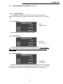
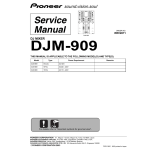
2. FRONT PANEL
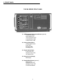
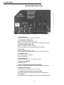
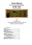
THE XM SERIES FRONT PANEL
2.4
2.5
2.1
2.2
2.3
2.1 - APM Automatic Performance Monitor (optional)
"Test/Reset" Switch
"Not Installed" LED
"Test in Progress" LED
"Check Batteries" LED
"Check Inverter" LED
2.2 - Charger Status Block
"Charge Mode" Switch
"Float" LED
"Equalize" LED
"Recharge" LED
2.3 - System Status Block
"Line Power" LED
"Standby Power" LED
"AC Output" LED
2.4 - Output Current Display
LED Display
2.5 - Standby Data Display (optional)
"Mode" Switch
"Elapsed Time" LED
"Standby Events" LED
Time/Events Window
6
2. FRONT PANEL
FRONT PANEL
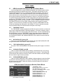
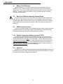
2.1
APM (Automatic Performance Monitor) Status Block
On units equipped with an optional APM logic upgrade, the XM Series power module
automatically self-tests the batteries and inverter. The duration and intervals are user
programmable (see section 6.10). If a failure is detected during self-test, either the red
"CHECK BATTERIES" or red "CHECK INVERTER" LEDs in the APM status block will
flash to indicate the circuit that has failed. At the same time, the external LRI option on
the enclosure will flash to signal that maintenance is required. The APM self-test feature
is a great aid when trouble-shooting the power supply and can be manually activated by
pressing the "TEST/RESET" switch. The yellow "TEST IN PROGRESS" LED will light as
the power supply transfers into self-test mode. The red "STANDBY POWER" LED in the
SYSTEM STATUS block will come ON to indicate that the power supply is in inverter
operation. Since self-test only simulates an outage, the green "LINE POWER" LED will
remain ON, indicating that utility power is still available. If a fault is detected, the power
supply will transfer back to line power without interruption to the output.
2.1.1 "TEST/RESET" Switch
The "TEST/RESET" switch is standard on all XM Series power modules, but functional
only on units equipped with APM or USM logic upgrades. It is used to manually cycle the
power supply in and out of self-test mode, and to reset alarms. If a fault is detected during
the APM self-test mode, the "TEST/RESET" switch resets the enclosure’s flashing LRI
(Local and Remote Indicator) and the SSR (Standby Status Relay) alarms; however, the
red "CHECK BATTERIES" and "CHECK INVERTER" LEDs cannot be reset until the fault
is corrected.
2.1.2 "NOT INSTALLED" (green) LED
On units not equipped with an APM logic upgrade, the green "NOT INSTALLED" LED
will light whenever the "TEST/RESET" switch is pressed.
2.1.3
"TEST IN PROGRESS" (yellow) LED
The yellow "TEST IN PROGRESS" LED indicates that the power supply is in self-test
mode.
2.1.4 "CHECK BATTERIES" (red) LED
If the red "CHECK BATTERIES" LED is flashing, it indicates that one or more of the
batteries are unable to carry the load and that maintenance is required. The flashing LED
cannot be reset until the fault is corrected. NOTE: Under this condition, the power supply
will not be able to support inverter operation.
2.1.5 "CHECK INVERTER" (red) LED
If the red "CHECK INVERTER" LED is flashing, it indicates that the inverter has failed
to produce AC and that maintenance is required. The flashing LED cannot be reset until
the fault is corrected. NOTE: Under this condition, the power supply will not be able to
support inverter operation.
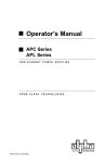
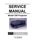
APM (Automatic Performance Monitor) Status Block
"TEST/RESET" Switch
(Manually initiates self-test; resets alarm)
"NOT INSTALLED" (green) LED
(Illuminates if TEST/RESET switch is pressed
with APM option not installed)
"TEST IN PROGRESS" (yellow) LED
(Indicates self-test mode)
"CHECK BATTERIES" (red) LED
(Indicates battery failure)
"CHECK INVERTER" (red) LED
(Indicates inverter failure)
(OPTIONAL FEATURE)
7
2. FRONT PANEL
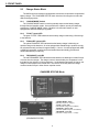
2.2
Charger Status Block
The XM Series power module is equipped with a dual mode, temperature-compensated
battery charger. The "CHARGER STATUS" block is broken into categories to reflect the
different charging modes:
2.2.1 "CHARGE MODE" Switch
The "CHARGE MODE" switch is used to manually sequence the battery charger
through float and equalize modes. On non-APM units, equalize can only be initiated by
pressing the "CHARGE MODE" switch. Equalize is an automatic feature on units
equipped with APM and USM logic upgrades.
2.2.2 "FLOAT" (green) LED
The green "FLOAT" LED indicates that the battery charger is delivering a float charge
to the batteries.
2.2.3 "EQUALIZE" (yellow) LED
The yellow "EQUALIZE" LED indicates that the battery charger is delivering an
equalize charge to the batteries. On units equipped with standard logic, equalize can only
be activated manually and lasts for approximately 1.2 hours. On units equipped with APM
or USM logic upgrades, equalize can be activated either automatically (pre-selected
duration and interval) or manually.
2.2.4 "RECHARGE" (red) LED
The red "RECHARGE" LED indicates that the batteries are drawing more than 5 Amps
of current from the charger. The charge current is determined by the acceptance level of
the batteries, but limited to 10 Amps maximum. As the batteries approach full charge, the
charger’s current tapers off to normal float. The red LED is ON only when the charge
current exceeds 5 Amps in either float or equalize modes.
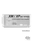
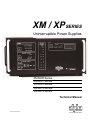
CHARGER STATUS Block
"CHARGE MODE" Switch
(Manually sequences charger)
"FLOAT" (green) LED
(Indicates float charge to the batteries)
"EQUALIZE" (yellow) LED
(Indicates equalize charge to the batteries)
"RECHARGE" (red) LED
(Indicates a charge current > 5 Amps)
(STANDARD FEATURE)
8
2. FRONT PANEL
2.3
System Status Block
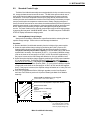
The "SYSTEM STATUS" block is broken into three categories to quickly identify the
power supply's operational status: running on AC line power; running on batteries; and
nominal output power to the load.
2.3.1 "LINE POWER" (green) LED
The green "LINE POWER" LED indicates that power from the utility is present and that
the power supply is operating in AC LINE mode.
2.3.2 "STANDBY POWER" (red) LED
The red "STANDBY POWER" LED indicates that the power supply is operating from
its battery backup. When AC from the utility is lost, the green "LINE POWER" LED goes
OFF and the red "STANDBY POWER" LED comes ON as the unit transfers to inverter
operation. Whenever the red LED is ON, the unit is running on backup power.
2.3.3 "AC OUTPUT" (green) LED
The green "AC OUTPUT" LED indicates that acceptable voltage is available at the
power module's output. Regardless of the input mode, "LINE POWER" or "STANDBY
POWER," the "AC OUTPUT" LED should remain ON at all times.
SYSTEM STATUS Block
"LINE POWER" (green) LED
(Indicates the presence of utility AC)
"STANDBY POWER" (red) LED
(Indicates inverter operation)
"AC OUTPUT" (green) LED
(Indicates acceptable output voltage)
(STANDARD FEATURE)
9
2. FRONT PANEL
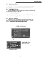
2.4
Output Current Display
The amount of current from the power supply to the load is indicated by the "OUTPUT
CURRENT" display. The LED display is useful for determining the overall status of the
load. When there is no load connected, the LEDs on the display will be OFF. In situations
where LEDs light above the rated output of the power supply, such as 18 or 20 Amps, an
overload or short circuit condition exists in the load.
2.4.1 LED Display
The LEDs are set in 2 Amp increments from 2 to 20 Amps; however, the display is
accurate to 1 Amp. When the output current falls between increments, both adjacent LEDs
light.
OUTPUT CURRENT Display
LED (green) Display
(Displays output current in 2 Amp increments.
When the output reading falls between increments,
adjacent LEDs light as shown.)
(STANDARD FEATURE)
10
2. FRONT PANEL
2.5
Standby Data Display (SDD)
The optional, dual-function LED "STANDBY DATA" display is used to keep track of
accumulated inverter run time, and to record the number of standby events that have
occurred. The "ELAPSED TIME" clock is activated only when the power supply is in
inverter mode. Elapsed time will continue to accumulate until the clock is reset. The
"STANDBY EVENTS" counter displays the number of standby events that have lasted
longer than 60 seconds duration. Standby events will continue to accumulate until the
counter is reset. The SDD is equipped with an on-board battery to maintain data even
when the main circuit module is completely removed or a complete power outage (including
low battery shutdown) occurs .
2.5.1 "MODE" Switch
The "MODE" switch activates the display and verifies the mode of operation. When
the switch is pressed, the "ELAPSED TIME" LED will light (or "STANDBY EVENTS" LED
depending upon the mode). At the same time, the corresponding information will appear in
the "TIME/EVENTS" window for approximately 10 seconds. The next mode is activated
by pressing the switch again. "ELAPSED TIME" and "STANDBY EVENT" information can
be toggled by briefly pressing the "MODE" switch.
NOTE: To clear either the "ELAPSED TIME" or "STANDBY EVENT" memory, select
the desired mode. Press and hold the "MODE" switch until the LED flashes. Then, press
the MODE switch twice (in rapid succession). A single decimal point will appear in the
display when the memory has been cleared.
2.5.2 "ELAPSED TIME" LED
The "ELAPSED TIME" LED indicates the mode as the "TIME/EVENTS" window
displays the time accumulated during inverter operation. The clock, which displays time to
the nearest 0.1 hours, will continue to accumulate time until the memory is manually
cleared.
2.5.3 "STANDBY EVENTS" LED
The "STANDBY EVENTS" LED indicates the mode as the "TIME/EVENTS" window
displays standby events that have lasted more than 60 seconds in duration. The counter
will continue to register standby events until the memory is manually cleared.
2.5.4 "TIME/EVENTS" Window
The "TIME/EVENTS" window displays "ELAPSED TIME" in 0.1 hr increments, up to
999.9. "STANDBY EVENTS" are displayed in increments of 1, up to 9999.
STANDBY DATA Display
(OPTIONAL FEATURE)
"MODE" Switch
(Selects TIME or EVENTS mode; clears memory)
"ELAPSED TIME" (green) LED
(Indicates ELAPSED TIME mode)
"STANDBY EVENTS" (green) LED
(Indicates STANDBY EVENTS mode)
"TIME/EVENTS" Window
(Displays TIME and EVENTS information)
11
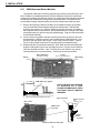
2. SIDE PANEL
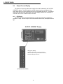
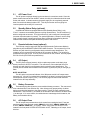
THE XM SERIES SIDE PANEL
7
8
9
6
10
11
1
2
3
4
5
1. - AC Power Cord
(Connects to the enclosure's convenience outlet.)
2. - Standby Status Relay (SSR)
White (1) = Common; Red (2) = N.O. / N.C.
(Select contact normally open / closed with wire on back plane board.)
3. - Remote Indicator Lamp (LRI)
Black (3) = Negative; Red (4) = Positive
(Connects to pole-mount enclosure's optional external lamp)
4. - AC Output
White (5) = Neutral; Black (6) = Hot
(Connects to SPI Service Power Inserter; or ACI Lamp option / SPI)
5. - Battery Connector
Red = Positive; Black = Negative
(Connects to batteries)
6. - AC Output Fuse
(XM 6015 = 20A; XM 6012 = 15A; XM 6010 = 12A)
7. - Battery Circuit Breaker
(60 Amp magnetic)
8. - Main Circuit Module Assembly Access Handle
(Access to 10A Battery Charger fuse; APM and USM logic upgrades)
9. - USM Connector Access
(Used for status monitoring interface connections)
10. - Remote Temperature Sensor Connector (RTS)
(Connects to charger for exact battery temperature measurements)
11. - Data Port
(Used for data retrieval and diagnostic testing with optional DataLogger)
12
3. SIDE PANEL
SIDE PANEL
3.1
AC Power Cord
The AC power cord plugs directly into the enclosure’s convenience outlet. Since the
power module does not have an ON/OFF switch, the utility circuit breaker should be used
as the main switch. In situations where the power supply is to be completely powered
down, first switch the battery breaker OFF. This will prevent the unit from going into
inverter operation when utility AC is removed.
3.2
Standby Status Relay (optional)
On APM and USM units equipped with the SSR (Standby Status Relay), a dry
“Form C” contact accommodates systems requiring remote alarms. The left connector (1)
white is configured as common. The right connector (2) red is configured “normally open”
(contacts close when alarm is present). For special applications, contact 2 can be configured “normally closed” (contacts open when alarm is present) by repositioning the wire
located on the module's back plane board from position P104 to P105.
3.3
Remote Indicator Lamp (optional)
The LRI lamp, used in conjunction with the APM (Automatic Performance Monitor),
plugs directly into the REMOTE INDICATOR LAMP connector. The connector fits in one
direction only with the wiring configuration clearly marked for easy identification. The
(negative) wire is connected to the left side of the connector (3) black. The (positive) is
connected to the right (4) red. The LRI circuit is rated at 24 VDC, 250mA. Use only Alpha
P/N 740-139-20 (24 Volt LRI Lamp and Socket).
3.4
AC Output
The SPI (Service Power Inserter), which couples output power to the load, plugs
directly into the AC OUTPUT connector. The connector is color-coded and fits in one
direction only with the wiring configuration clearly marked for easy identification. The
(neutral) wire is located on the left side of the connector (5) white; the (hot) on the right (6)
black.
NOTE: ACI OPTION
The ACI option is an external indicator of the XM power module's AC output status
(see page 16). If the ACI is included in the installation, the lamp's connector plugs directly
into the power module's output (5 & 6). The SPI then plugs into the second connector
located on the ACI lamp assembly.
3.5
Battery Connector
The batteries plug directly into the power module's battery connector. The connector is
color-coded and fits in one direction only. Note: Always verify proper polarity of cables
before connecting the batteries to the power module. Polarity is clearly marked for easy
identification. The red cable (+) is located on the left side of the connector; the black cable
(-) on the right. If, for some reason, the cables become interchanged at the batteries, the
battery circuit breaker will trip.
3.6
AC Output Fuse
The AC output fuse prevents short circuit current from entering the load. Fuses are
rated according to the particular model: (XM6015 = 20 A 250V; XM6012 / XM6012 E = 15
A 250V; XM6010 / XM6010 E = 12 A 250V). NOTE: If the green "AC OUTPUT" LED
located in the front panel SYSTEM STATUS block is OFF, indicating no AC output, check
this fuse.
13
3. SIDE PANEL
3.7
Battery Circuit Breaker
The 60 Amp battery circuit breaker is used to disconnect the batteries from the
module's DC circuit. With the breaker turned off, the power supply will not transfer to
standby mode. The inverter is disabled and the battery charger is unable to charge the
batteries. If a short circuit occurs in the DC circuitry, or battery polarity is accidently
reversed, the breaker will trip.
3.8
Main Circuit Module Assembly Access Handle
The main circuit module can be removed by firmly pulling the handle located on the
side of the unit. This facilitates easy access for logic upgrades, selection of float and
equalize charges and internal fuse replacements. The assembly can be removed during
LINE operation without interruption to the output. NOTE: See cautionary statements in
Section 6.8.
3.9
USM Connector Access
A cutout is provided in the Main Circuit Module Assembly to allow access to the board
connectors located on the USM logic upgrade. Status Monitoring communications and
tamper switch cables plug directly into the board's keyed connectors.
3.10
Remote Temperature Sensor Connector (RTS)
The Remote Temperature Sensor plugs directly into the "RJ-11C" type connector
located on the side panel. The sensor end of the RTS is routed into the battery compartment and taped directly to the side of the center battery. This provides precise battery
temperature measurements in order to accurately adjust the battery charge voltage with
changes in battery temperature. If the remote temperature sensor is not connected, a
temperature sensor in the main circuit module adjusts the battery charge voltage with
changes in ambient temperature within the power supply.
3.11
Data Port
The Data Port is used in conjunction with optional hand-held DataLogger to retrieve and
store data directly from the power module during routine preventive maintenance. Caution:
No other devices should be plugged into the data port.
14
4. STANDARD FEATURES
STANDARD FEATURES
XP Series Uninterruptible Power Supplies are available in the following packages:
XM Series Power Module with standard control logic; Pole-mount enclosure (PME)
complete with galvanized mounting brackets, Service Power Inserter (SPI),
“High Magnetic” circuit breaker and duplex receptacle. Optional pole (PWE) and
ground-mount (UPE and UPE/M) enclosures are available. Batteries are separate.
4.1
XP6005 Series Uninterruptible Power Supplies
*XM6005-24 J5 Module - (100 VAC, 50 Hz Input) / (60 VAC, 5.3 Amp, 320 VA Output)
*XM6005-24 J6 Module - (100 VAC, 60 Hz Input) / (60 VAC, 5.3 Amp, 320 VA Output)
4.2
XP6007 Series Uninterruptible Power Supplies
XM6007 Module (120 VAC, 60 Hz Input) / (60 VAC, 7 Amp, 420 VA Output)
XM6007 E Module (230 VAC, 50 Hz Input) / (60 VAC, 7 Amp, 420 VA Output)
XM6007 P Module (220 VAC, 60 Hz Input) / (60 VAC, 7 Amp, 420 VA Output)
4.3
XP6010 Series Uninterruptible Power Supplies
XM6010 Module (120 VAC, 60 Hz Input) / (60 VAC, 10 Amp, 600 VA Output)
XM6010 E Module (230 VAC, 50 Hz Input) / (60 VAC, 10 Amp, 600 VA Output)
XM6010 P Module (220 VAC, 60 Hz Input) / (60 VAC, 10 Amp, 600 VA Output)
*XM6010-24 Module (120 VAC, 60 Hz Input) / (60 VAC, 10 Amp, 600 VA Output)
4.4
XP6012 Series Uninterruptible Power Supplies
XM6012 Module (120 VAC, 60 Hz Input) / (60 VAC, 12 Amp, 720 VA Output)
XM6012 E Module (230 VAC, 50 Hz Input) / (60 VAC, 12 Amp, 720 VA Output)
4.5
XP6015 Series Uninterruptible Power Supplies
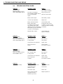
XM6015 Module (120 VAC, 60 Hz Input) / (60 VAC, 15 Amp, 900 VA Output)
XM6015 E Module (230 VAC, 50 Hz Input) / (60 VAC, 15 Amp, 900 VA Output)
XM6015 J5 Module (100 VAC, 50 Hz Input) / (60 VAC, 15 Amp, 900 VA Output)
XM6015 J6 Module (100 VAC, 60 Hz Input) / (60 VAC, 15 Amp, 900 VA Output)
XM6015 P Module (220 VAC, 60 Hz Input) / (60 VAC, 15 Amp, 900 VA Output)
*XM6015-48 SE Module (230 VAC, 50 Hz Input) / (60 VAC, 15 Amp, 900 VA Output)
Alpha Technologies also manufactures:
XM4808 E (230 VAC, 50 Hz Input) / (48 VAC, 8 Amp, 384 VA Output)
*XM4808-24 E (230 VAC, 50 Hz Input) / (48 VAC, 8 Amp, 384 VA Output)
* Note: "-24" models utilize a 24 VDC battery system; "-48" models utilize a 48 VDC battery
system. All other models listed utilize a 36 VDC battery system.
15
5. OPTIONAL FEATURES
OPTIONAL FEATURES
The following options can be ordered factory installed or, in most instances, can be
field retrofitted by qualified service personnel.
5.1
APM-XP (Automatic Performance Monitor)
The APM-XP is a field replaceable, plug-in logic card that plugs directly into the edge
connector located on the back of the main circuit module. It upgrades the power supply's
standard logic functions to include a self-test feature that automatically tests the batteries
and inverter at pre-selected intervals. If a problem is detected during the self-test mode,
the APM activates an alarm circuit and flashes the red "CHECK BATTERIES" or "CHECK
INVERTER" LEDs, located on the front panel, to indicate the circuit that has failed the
test.
5.2
USM (Universal Status Monitor)
The USM is a field replaceable, plug-in logic card that allows the XP Series power
supply to be configured for pre-existing status monitoring systems. It can be configured
for parallel or serial applications. The USM facilitates use with common amplifier monitoring systems such as Scientific Atlanta “6585” (SA), Magnavox “6DSS” (M), Jerrold “RSM”
(J), AM Communications “TMC-8061” (AM), Texscan “Vital Signs” (T) and C-COR “Quick
Alert” (C). For systems utilizing AlphaSoft status monitoring software, the USM-(A) can be
manipulated, manually or automatically, to provide information such as battery condition,
inverter operation, and alarm status.
5.3
LRI (Local and Remote Indicator)
Used in conjunction with APM and USM logic upgrades, the LRI lamp (red) is located
on the outside of pole-mount enclosures and duplicates the function of the module's
"STANDBY POWER" LED in the System Status block. The lamp comes ON only when
the power supply is running on backup power (STANDBY). During normal AC line operation, the lamp remains OFF. Whenever a fault is detected during the APM self-test, the
lamp flashes to indicate that service is required . The LRI can be used as a simple form of
status monitoring by allowing cable technicians to check the operational status of the
power supply without having to climb the pole and open the enclosure.
5.4
ACI (AC Indicator)
The AC Indicator (green) is located next to the LRI lamp on the outside of pole-mount
enclosures. The ACI is similar in function to the module's (green) "AC OUTPUT" LED in
the System Status block. As long as there is voltage present at the output, the ACI lamp
remains ON. As with the LRI, this acts as a simple form of status monitoring by allowing
cable technicians to check the output status of the power supply without having to climb
the pole and open the enclosure.
5.5
SDD (Standby Data Display)
The dual-function, "STANDBY DATA" display is used to keep track of accumulated
inverter run time, and to record the number of standby events. The "ELAPSED TIME"
clock is activated only during inverter operation. The "STANDBY EVENTS" counter
displays the number of standby events lasting longer than 60 seconds in duration.
5.6
SSR (Standby Status Relay)
On APM and USM units equipped with the "STANDBY STATUS RELAY," dry "Form
C" contacts are provided to accommodate systems requiring remote alarms. If, during the
APM self-test function, a fault is detected, the alarm circuit will activate. The contacts are
configured "common“ and "normally open” (contacts close when alarm is present). The
contacts can be reconfigured "normally closed” (contacts open when alarm is present) by
moving a wire located on the module's back plane board.
16
5. OPTIONAL FEATURES
5.7
LA-P (Lightning Arrestor)
The LA-P consists of a 350 Joule, Metal Oxide Varistor (MOV). It plugs directly into
the enclosure’s convenience outlet, eliminating the need for hard-wired MOVs. Enclosed in
a plastic housing, the LA-P is used to provide additional protection from voltage spikes
caused by lightning and other power disturbances. No wiring is necessary.
5.8
BCK-X (Battery Cable Kit)
Battery Cable Kits are heavy-duty wiring assemblies used to connect (3) gelled
electrolyte, or equivalent batteries to the power module. All kits come with mounting
hardware and a quick connect.
5.9
BCK-FX (Fused Battery Cable Kit)
Fused Battery Cable Kits are available for applications requiring additional battery
circuit protection. Cables come with a 40A in-line fuse.
5.10
BMO (Battery Mat Option)
Used for a variety of applications, the rubber battery mat provides additional thermal
isolation and battery shelf protection in PME enclosures.
5.11
BTO (Battery Tray Option)
Used mainly with less common wet cell applications, the BTO is designed to contain
and prevent electrolyte from leaking onto the enclosure's shelf. It can also be used to
provide additional thermal isolation from the power module. Battery trays are constructed
of PVC and accommodate individual battery sizes up to Group 31. PME enclosures only.
5.12
MST (Module Slide Tray)
The MST is designed for use on PME and PWE pole-mount enclosures only and is
compatible with all XM Series power modules. The MST's movable platform rides on a set
of heavy-duty ball bearing slides to promote access to the power module during servicing.
It is available factory installed or as a field retrofit kit.
5.13
DSE (Delete Service Entrance)
For installations requiring an externally-mounted service disconnect, the enclosure's
internal service entrance, if equipped, can be removed. The DSE option, which must be
specified at the time of order, eliminates the internal service entrance assembly. A Square
D 15 Amp "HM" high magnetic circuit breaker (for use with the external service disconnect)
and duplex outlet are included with this option.
5.14
ISE (Internal Service Entrance)
For applications requiring an internal service disconnect to be located inside the
enclosure, the ISE option features a Square D 15 Amp "HM" high magnetic circuit breaker,
an agency approved service disconnect box and duplex outlet.
5.15
STH (Storm Hoods)
Storm hoods are used on PME and PWE pole-mount enclosures to prevent snow from
entering the enclosure during blizzard conditions. Specify the type of enclosure when
ordering.
5.16
XPA (XP Adaptor)
The XPA contains a set of quick connects used to adapt existing Alpha enclosures,
previously wired for AM Series power products, for use with XM Series power modules.
17
5. OPTIONAL FEATURES
5.17
APP60S (Service Power Supply)
The APP60S is a portable, non-standby power supply used to provide conditioned AC
power to the load when the main power module is out of service. A front panel switch
allows the APP60S to be set for 30 VAC or 60 VAC applications. Used in conjunction with
the “Jones” connector and "ALT/ON" switch located on the enclosure's SPI (Service Power
Inserter), power can be transferred from the main module to the APP60S without interrupting the load.
5.18
Batteries
Sealed, gelled electrolyte (no maintenance) batteries are recommended for use with
XP Series uninterruptible power supplies. The majority of Cable Television and Broadband
LAN operators prefer this type of battery due to its exceptional performance, safety record
and service life. Batteries are available in ratings of 75Ah and 100Ah.
5.19
ABC-12 (Battery Charger)
The ABC-12 is designed for use with 12 volt specialty batteries such as gelled electrolyte products used in communications, UPS and standby applications. Selectable float or
equalize charge modes optimize battery recharging. The charger is ideal for recharging
batteries that have been in lengthy storage, plus batteries can be re-balanced using a
parallel charge before use in series applications.
5.20
Enclosures
The XM Series power module can be used in either pole or ground-mount installations.
Pole-mount enclosures, PME (for cold climates) and PWE (for warm climates), are constructed of heavy-duty aluminum and come with two, galvanized steel mounting brackets.
UPE and UPE/M ground-mount enclosures are constructed of heavy-duty aluminum and
come with Galvanized (UPE/M only) steel doors. Alpha enclosures are vented to promote
natural convection cooling and prolong battery life.
Alpha enclosures contain separate compartments for the batteries and power module.
The battery compartment accommodates (3) Group 31 gelled-electrolyte, no-maintenance
batteries and is equipped with a battery slide tray (except PME) for easy access. The
module compartment accommodates the power module, a 15 Amp "HM" circuit breaker
assembly, duplex receptacle and SPI (Service Power Inserter). The AC power connection
to the breaker assembly is made through a conduit knockout on the rear of the PWE
enclosure or through the base of the PME, UPE and UPE/M. The cable connection is
made directly to the SPI’s "VSF" coaxial fitting located on the rear of the PWE, or at the
base of the PME, UPE and UPE/M. There is adequate space in the module compartment
to accommodate a variety of power modules, indicator lamps, and components used for
status monitoring.
5.21
PS Series (Pedestal Supports)
Alpha pedestal supports provide a quick, one-step solution for ground-mount enclosure
installations. Constructed of pre-formed, high density polyethylene (HDPE), the pedestal
support eliminates the need for costly concrete work. The large body design provides
excellent "hand hole" working space, allowing room for cable bends, wire loops and
grounding connections. Pedestal supports are available for use with Alpha UPE, UPE/M,
PWV/PED, PED/M and PMD/PED ground-mount enclosures.
5.22
DataLogger
The hand held DataLogger is used to run diagnostics, manipulate the APM (Automatic
Performance Monitor), and to test individual battery voltages. Maintenance data, such as
Input Line Voltage, Output Current, Battery Voltage, Battery Charge Voltage (float and
equalize), Battery Charge Current, Inverter Events, Accumulated Inverter Run Time,
Technician ID Number, Power Supply Address, Test Date and Time, can be retrieved and
stored in the DataLogger. Data from as many as 32 power supplies can be downloaded to
a DOS compatible computer at the headend to create a maintenance history file, thus
automating data retrieval, log entry and consistent data formatting.
18
5. OPTIONAL FEATURES
5.23
AC Series (Amp Clamp)
Alpha Technologies’ Amp Clamps are designed to protect active and passive equipment (such as amplifiers and power inserters) from voltage surges and transients. Amp
Clamps can be ordered as retrofit kits, or factory installed in the desired host hardware. A
Product/Serial Number label is included with each kit so that retrofitted equipment can be
easily identified. The Amp Clamp circuit consists of two, rugged SCRs (silicon controlled
rectifiers) connected in an inverse parallel configuration with a steady state current rating of
35 Amps and a one cycle (8 ms) pulse rating of 500 Amps. The SCRs are triggered into
conduction whenever the Amp Clamp’s bi-directional trigger diode senses the presence of
voltage transients exceeding its 104 - 115 Volt peak threshold. The fast response trigger
diode gates the appropriate SCR ON (in nanoseconds) to shunt the surge current to
ground, effectively protecting sensitive equipment from transient overvoltage conditions.
The Amp Clamp is compatible with the following host hardware: C-COR PS-550-C power
inserter, PS-900-C power inserter and T500 amplifiers (6 & 8 port); G.I./Jerrold SSP-PI
power inserter, SSP-3 two-way splitter and SSP-(7, 9, 12, or 16 ) directional couplers;
Lindsay LPI-100 and 1GHz LPI-100 power inserters; Magnavox 4-LPI, 5-LPI, 8-LPI, 49LPI and 59-LPI power inserters; RCA PI-1 power inserter; RMS CA-5400 and UP-6400
power inserters, and CA-5402/RFI two--way splitter; Scientific Atlanta SAIF-RFI power
inserter; Regal RPI-60 (blue) power inserter; and Antronix RPI-60 (green) power inserter.
If your equipment is not listed, contact Alpha Technologies for availability.
5.24
CAT-PAK (Computer Aided Training)
Computer Aided Training for power supply maintenance is available for either MAC® or
IBM® (and compatible) formats. Technicians can learn and develop maintenance skills at
their own pace before leaving the office, thus reducing overall maintenance time and
standardizing maintenance practices. Even though the CAT-PAK training program was
developed for use with AP Series power products, the overall information can be applied to
XP installations. The program can be manipulated entirely by the user without the need for
assistance. Complete system packages, including hardware and software, are available
from Alpha Technologies. Please specify format and disk requirements (3 1/2" or 5 1/4")
when ordering.
5.25
Instructional Videotapes
Instructional videotapes are available for Alpha power products including Product
Overview, Theory of Operation, Installation, and Maintenance. Developed primarily for use
with AP Series power products, the tapes contain useful information that can be applied to
XP installations. Each tape is available in either NTSC (VHS) or PAL formats and covers
all aspects of the Alpha Standby Power Supply. Transcripts of each tape are available
upon request.
"Alpha Technologies: Market Leader in Standby Power" (P/N 048-082-00) is a 20
minute presentation which highlights standby power products and emphasizes reliability,
ease of operation and customer service.
"The Alpha Standby Power Supply" (P/N 048-070-00) is a 10 minute conceptual overview of the Alpha standby power supply. The tape covers the advantages and disadvantages of forward and reverse transfer systems and compares them to Alpha's approach to
standby power.
"Installing the Alpha CATV Standby Power Supply" (P/N 026-006-B4) is a 20 minute,
step-by-step, description of the installation process. The tape includes ground and polemount applications, start-up procedures and testing the unit.
"Power Supply Maintenance for AP and AM Series Power Products" (P/N 026-006-B2
[108-3]) is a 30 minute presentation that covers all aspects of AP Series standby power
supply operation and recommended maintenance procedures.
19
6. INSTALLATION
INSTALLATION
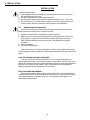
To ensure operator safety:
1. Power supplies should be installed only by qualified personnel and in accordance
with applicable electrical codes.
2. Use eye protection whenever working with batteries.
3. Use only sealed, lead-acid type batteries (gelled-electrolyte or equiv., 55 Ah min.)
4. Use a bucket truck, or suitable climbing equipment such as a safety harness and
climbing spikes, whenever installing or servicing pole-mount installations.
6.1
Unpacking and Inspection
Carefully remove the power module and enclosure from their shipping containers.
Make sure that the following items have been included:
1. XM Series Power Module (including BCK-X battery cable kit).
2. PME Pole-mount enclosure (with two, galvanized mounting brackets, SPI service
power inserter, 15 Amp "HM" circuit breaker assembly with duplex receptacle).
PWE, UPE and UPE/M are optional enclosures. Note: Batteries are shipped
separately.
3. Operator's Manual.
4. Any other ordered options.
Inspect the contents. If items are damaged or missing, contact Alpha Technologies
and the shipping company immediately. Most shipping companies have only a short claim
period.
SAVE THE ORIGINAL SHIPPING CONTAINER.
In the event a unit needs to be returned for service, it should be packaged in its
original shipping container. If the original container is not available, make sure the unit is
packed with at least three inches of shock-absorbing material to prevent shipping damage.
Note: Do not use popcorn-type material. Alpha Technologies is not responsible for
damage caused by improper packaging on returned units.
READ THE OPERATOR'S MANUAL.
Become familiar with the power supply's front and side panel. Review the drawings
and illustrations contained in the manual before proceeding. If you have questions regarding the safe installation or operation of this unit, contact Alpha Technologies or your
nearest Alpha representative.
20
6. INSTALLATION
6.2
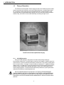
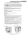
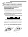
Pole-mount Enclosure Installation (PME and PWE)
PME and PWE enclosures are designed to be mounted on wooden poles; however,
special brackets are available for concrete pole applications. Mounting bolts should go
completely through the wooden pole and be secured from the back with a large washer and
nut. The two galvanized mounting brackets mount between the enclosure and pole. Most
codes require the base of the enclosure to be located a minimum height from the ground.
Always verify height restrictions before proceeding. (Refer to the pole-mount drawings
located at the back of the manual.)
NOTE: THE MAJORITY OF POLES ARE THE PROPERTY OF THE LOCAL UTILITY.
BEFORE INSTALLING AN ENCLOSURE, THE LOCATION AND THE METHOD OF
MOUNTING MUST BE APPROVED BY THE UTILITY.
Materials required:
Two (2) 5/8" dia. machine bolts (UNC thread) SAE Grade 5 or better, length to suit pole;
Two (2) 5/8" dia. zinc-plated flat washers;
Two (2) 5/8" dia. hex nuts (UNC thread).
Tools required:
Auger or drill for boring 3/4" dia. holes in the wooden pole;
Mallet or hammer;
Assorted sockets or wrenches.
Procedure:
1. Unpack the galvanized brackets and turn the enclosure face-down on a soft surface.
2. Slide one bracket up through the lower mounting strap on the rear of the enclosure.
The bracket’s flanges face away from the enclosure. Secure the lower mounting
bracket using the 3/8" x 3/4" hex bolt included with the enclosure.
3. Mark the position for the upper mounting bracket on the utility pole. Drill a 3/4" hole
completely through the pole. Secure the bracket with a 5/8" machine bolt, washer and
nut. Do not fully tighten the bolt at this time.
4. Position the enclosure on the upper mounting bracket. It may be necessary to slightly
rock the enclosure and pull downward to properly seat it on the bracket. Center the
enclosure on the pole.
5. Mark the hole for the lower mounting bracket. Lift the enclosure off of the top bracket
and drill the lower hole. Spacing between the holes should be 18.0" on center.
6. Slide the enclosure back into place over the top mounting bracket. Align the lower
bracket with the hole and secure it with a 5/8" machine bolt, washer and nut. Tighten
both brackets until the flanges dig into the wood approximately 1/4".
7. The enclosure is now ready for the utility connection, power module and batteries.
Upper Mounting Bracket
5/8" Dia. "Through" Bolts
5/8" Dia. "Through" Bolts
PME
Cable Power Out
PWE
Nut & Washer
Nut & Washer
ACI / LRI
Options
18"
Chassis
Ground
18"
ACI / LRI
Options
Chassis Ground
Utility Power In
Cable Power Out
Utility Power In
Lower Mounting Bracket
Lower Mounting Bracket
PME and PWE Pole-mount Enclosures
21
6. INSTALLATION
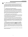
6.3
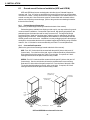
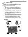
Ground-mount Enclosure Installation (UPE and UPE/M)
UPE and UPE/M enclosures are designed to bolt directly to a Pedestal Support or
concrete pad. Four 1/2" holes are provided in the base of the enclosure to accommodate
3/8" Anchor or J-bolts. Secure the enclosure using a flat washer, lock washer and 3/8" nut
at each mounting bolt. Note: Enclosures must be mounted flush with a smooth surface
and not over-torqued to prevent damage. (Refer to the ground-mount drawings located at
the back of the manual).
6.3.1 Pedestal Support Preparation
(Refer to the pedestal support drawings located at the back of the manual).
Pedestal supports, available from Alpha, provide a quick, one-step solution for groundmount enclosure installations. Constructed of pre-formed, high density polyethylene, the
pedestal support eliminates the need for costly concrete work. The large body design
provides excellent "hand hole" working space, allowing room for cable bends, wire loops
and grounding connections. Pedestal supports are available for use with Alpha UPE and
UPE/M ground-mount enclosures. Installation is as easy as digging a hole to the appropriate depth to accommodate the base of the pedestal support and backfilling using a suitable
material. See 1.3.2 below for recommended utility and Cable TV conduit placements.
6.3.2 Concrete Pad Preparation
(Refer to the ground-mount drawings located at the back of the manual).
UPE - Four 3/8" J-bolts should be centered with the pad 24" (side to side) and 10"
(front to back). From the front of the pad, service conduits should be placed with the
utility entrance left of the center line; Cable TV to the right. If required, an 8' dedicated ground rod should be placed near the utility conduit.
UPE/M - Four 3/8" J-bolts should be centered with the pad 24" (side to side) and 14"
(front to back). Service conduits should enter the pad between the rear mounting
studs and 6" to either side of the pad's center line. From the front of the pad, Cable
TV conduit should be placed on the left; utility on the right. If required, an 8' dedicated ground rod should be placed near the utility conduit.
Utility Power Input
(Right Raceway)
Utility Meter
Compartment
Cable Power Output
(Left Raceway)
Cable
Power
Output
Utility
Power
Input
Pedestal Support
UPE
UPE/M
UPE and UPE/M Ground-mount Enclosures
22
6. INSTALLATION
6.4
Connecting Utility Power
CAUTION: THE FOLLOWING SHOULD BE PERFORMED ONLY BY QUALIFIED SERVICE
PERSONNEL AND IN COMPLIANCE WITH LOCAL ELECTRICAL CODES. CONNECTION
TO UTILITY POWER MUST BE APPROVED BY THE LOCAL UTILITY BEFORE INSTALLING THE POWER SUPPLY.
NOTE: UL AND NEC REQUIRE THAT A SERVICE DISCONNECT SWITCH (UL LISTED) BE
PROVIDED BY THE INSTALLER AND BE CONNECTED BETWEEN THE POWER SOURCE
AND THE ALPHA POWER SUPPLY. CONNECTION TO THE POWER SUPPLY MUST
INCLUDE AN APPROPRIATE SERVICE ENTRANCE WEATHER HEAD.
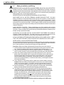
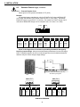
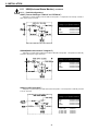
WIRING THE ENCLOSURE’S UTILITY SERVICE
Utility power enters the enclosure through a 1 1/8" opening at the bottom of PME, UPE
and UPE/M, and the rear of PWE. The enclosure accepts a standard electrical fitting. The
UPE is equipped with a service entrance mounted in the small compartment at the bottom
of the enclosure. The PME and PWE are equipped with a circuit breaker assembly located
in the enclosure’s module compartment. UPE/M is equipped with a dedicated utility
raceway.
IMPORTANT NOTE: A high-magnetic 15 Amp circuit breaker must be used in
order to accommodate the high inrush currents normally associated with the start-up
of ferroresonant transformers (400 Amp, no-trip, first-half cycle). Do not replace this
breaker with a conventional service entrance breaker.
High-magnetic circuit breakers for Square D service entrances are available from Alpha
Technologies.
Description
High Inrush Breaker
Ext. Serv. Disconnect
Alpha Part No.
470-013-10
020-085-10
Square D
Q0115HM
Q02-4L70RB
Wiring: (From duplex receptacle to service disconnect)
Alpha enclosures are equipped with a duplex receptacle to provide power to the UPS
and other peripheral equipment. The receptacle should protected by a 15 Amp, high
magnetic circuit breaker located inside the service disconnect. The receptacle's hot side
(black) is wired to the circuit breaker. The neutral (white) and ground (green) connect to the
service disconnect's neutral bus. A grounding clamp, located on the enclosure, facilitates
dedicated grounding. Note: Refer to the drawings at the back of the manual for detailed
wiring information.
In most cases, this configuration qualifies for service entrance use, however, other
codes may apply. Always contact your local utility to verify that the wiring conforms to
applicable codes.
AC Line (black)
Utility
Ground
AC Line (brown)
Neutral
Neutral
(white)
Ground
Outlet
Ground (green)
Ground (green)
Ground
Outlet
Ground (green)
AC
Line
AC Line (black)
Chassis Ground
Neutral
Neutral
(blue)
AC Line (brown)
Chassis Ground
Utility Grounding Clamp
on underside of enclosure
Utility Grounding Clamp
on underside of enclosure
120 VAC (60 HZ)
230 VAC (50 HZ)
Typical Circuit Breaker Assembly
23
AC
Line
6. INSTALLATION
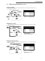
6.5
Connecting the SPI (Service Power Inserter)
Procedure: (Refer to SPI drawing located at the back of the manual)
1. Prepare the incoming coaxial cable.
2. Remove the two screws from the Service Power Inserter and lift off the cover.
3. Loosen the seizure screw on the PCB, (located inside the SPI), to accommodate the
center pin of the cable connector.
4. Screw the connector into the output port located on the rear of the PWE or UPE/M (or
lower compartment of the PME or UPE) enclosure. Make sure the center pin slides
through the seizure screw assembly. Heat shrink the external connection.
5. Tighten the seizure screw on the SPI so that the center pin on the cable connector is
firmly clamped. If a connection is left loose, arcing could result and possible damage
to the connector or SPI could occur.
6. Replace the cover on the SPI. NOTE: Make sure that the screws securing the SPI's
internal PCB to its chassis are tight; otherwise, loss of power, arcing, or possible
damage can occur. During routine maintenance, the seizure screw assembly can be
accessed through the grommeted hole without removing the SPI’s cover.
7. Once the module has been installed in the enclosure, the SPI connects to the AC
OUTPUT connector #5 (White) and #6 (Black) on the XM side panel (See section 6.6).
8. Make sure that the "ALT/ON" switch, located on the Service Power Inserter, is in the
"ON" position. When the switch is in the "ALT" position, the input is transferred to the
SPI's "Jones" connector which is used with an alternative power source such as the
Alpha APP60S Service Power Supply during module maintenance or replacement.
Power Supply Output Connector
(heatshrink connection)
SPI
(inside enclosure)
SPI
(inside enclosure)
Power Supply Output Connector
(heatshrink connection)
PME Enclosure
PWE Enclosure
Cable Connection to SPI
Coax Cable
(to power supply output connector)
Grommeted Hole
(seizure screw access)
"ALT/ON" Switch
"Jones" Connector
Black and White connectors
plug into 5 and 6 on XM module
SPI Service Power Inserter
(shown in PWE enclosure)
24
6. INSTALLATION
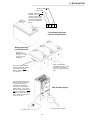
6.6
Power Module Installation
XM Series power modules are placed in the lower-right compartment of PME
enclosures; the upper-right compartment of PWE, UPE and UPE/M enclosures. The
enclosure's lid lifts and the door(s) can be removed. (Refer to the Module and Battery
Placement drawings located at the back of the manual).
Procedure:
1. Set the XM Series power module on the enclosure’s shelf.
2. Plug the connector from the SPI (Service Power Inserter) into the module's "AC
OUTPUT" connector. Make sure that the SPI’s "ALT/ON" switch is in the ON
position. NOTE: If the installation includes an ACI lamp option, plug the lamp's
connector into the module's "AC OUTPUT"; then, plug the SPI into the second
connector on the ACI.
3. Switch the module's "BATTERY" circuit breaker OFF. This will prevent the inverter
from starting when the batteries are first connected to the unit. Note: Do not switch
the battery breaker ON until the power module is running on utility AC.
4. Plug the quick connects from the battery cable into the module's "BATTERY"
connector. The connectors are keyed and color-coded to fit in one direction only.
5. If an optional LRI lamp (Local and Remote Indicator) is included, plug its cable into the
module's "REMOTE INDICATOR LAMP" connector.
6. If remote alarms are included in the installation, the cable should be plugged into the
module's "STANDBY STATUS RELAY connector. White (1) is configured common;
Red (2) is configured “normally open” (contacts close when alarm is present). The
contact can be configured “normally closed” (contacts open when alarm is present) by
moving the wire located on the module's back plane board from P104 to P105.
7. If the module is equipped with a Remote Temperature Sensor, plug the connector into
the RTS port (above the data port) located on the main circuit module assembly.
Route the sensor end of the cable into the battery compartment (see section 6.7).
NOTE: VERIFY BATTERY CHARGE VOLTAGES (SECTION 6.9) BEFORE STARTING THE
POWER SUPPLY.
PME Enclosure
PWE Enclosure
(same placement for UPE and UPE/M)
Battery
Breaker
AC Output
Fuse
RTS
Connector
Data
Port
*Remote
Alarm
LRI
Output
(SPI)
Batteries
USM
Cable Access
XM Series Power Module
25
6. INSTALLATION
6.7
Battery Installation and Wiring
WHENEVER INSTALLING OR REPLACING BATTERIES, DO NOT ALLOW LIVE BATTERY
WIRES TO CONTACT THE ENCLOSURE OR THE POWER MODULE CHASSIS. Insulate any
exposed wire ends with electrical tape. Shorting battery wires could result in a fire or possible
explosion. Make sure that the power module’s battery circuit is deactivated by switching the
battery breaker OFF, or removing the battery fuse.
WEAR EYE PROTECTION WHENEVER WORKING WITH BATTERIES.
MAKE SURE THAT ALL BATTERY TERMINAL CONNECTIONS ARE TIGHT. One major
battery manufacturer recommends that terminal connectors be torqued to 75 inch-pounds at
installation and then re-torqued to 60 inch-pounds during routine maintenance. Loose
connections will cause the unit to operate improperly. Use an approved battery terminal coating
such as NCP-2 to protect the terminals. If custom battery cables are made, they should be #8
AWG or larger and as short as practical. Battery terminals should be checked for corrosion and
cleaned if necessary.
CHECK BATTERY POLARITY. Polarity identifications are clearly marked at the module's
battery connector. A single battery connected backwards may go unnoticed until it is required
to perform. In the event polarity becomes accidently reversed at the batteries, the battery circuit
breaker will trip to protect the module.
IN ADDITION TO VOLTAGE CHECKS, ALWAYS INSPECT BATTERIES FOR SIGNS OF
CRACKS, LEAKS OR SWELLING. If a battery has one or more defective (shorted or high
impedance) cells, erratic operation or failure to provide standby power will result.
ALWAYS USE NEW BATTERIES WHEN FIRST INSTALLING A POWER SUPPLY. VERIFY
THAT THEY ARE THE SAME TYPE OF BATTERY WITH AN IDENTICAL DATE CODE.
NEVER INSTALL OLD OR UNTESTED BATTERIES.
Whenever batteries have been in storage for more than 3 months, they should be recharged for
(at least) 24 hours and checked under load prior to installation. Batteries with date codes older
than 2 years should not be used unless thoroughly recharged and tested.
Procedure: (Refer to the Battery Wiring drawing located at the back of the manual)
1. Place the batteries with the positive terminals forward on the enclosure’s shelf or slide
tray. Position the batteries with maximum ventilation space between them (+/- 1").
2. Interconnect the three batteries in series (negative to positive). The optional in-line
fuse if included, should be connected to the positive terminal on the right-hand battery.
3. Switch the module's battery breaker OFF to deactivate the DC circuit. Insert the
battery cable's red and black quick-connects into the module's color-coded connector.
Route the lugged ends of the cable through the grommeted holes in the enclosure’s
shelf and into the battery compartment. Connect the red cable (+) to the positive
terminal of the left-hand battery. Connect the black cable (-) to the negative terminal
of the right-hand battery.
4. Use a voltmeter to verify polarity and DC voltage at the module's battery connector.
Caution: Whenever making or breaking battery connections, never allow live battery
cables to contact the chassis. If necessary, wrap the lugs with electrical tape to
prevent arcing and temporarily disconnect one of the leads from the center battery.
5. Number the batteries 1 - 3 (left to right) using labels or masking tape. Record each
battery’s number and date code in the power supply's maintenance log.
6. The charger utilizes a remote temperature sensor (RTS) to provide precise battery
charger temperature compensation information. Uncoil the cable and plug the connector into the (upper) jack on the Main Module Assembly. The connector is keyed
and fits in one direction only. Route the sensor end of the cable into the battery
compartment and attach it to the side of the center battery using a high-strength
adhesive tape (see opposite page). In the event the sensor is disconnected, a
secondary sensor located on the main board provides temperature compensation
based upon ambient temperature.
Do not reset the battery breaker until the module is running on AC LINE power.
26
6. INSTALLATION
MONTH: (FEB) 02
YEAR: 1994
BATTERY TYPE: "A"
("FLOAT" Service Battery
containing gelled electrolyte acid.) Used for majority of Cable TV applications
due to its exceptional service life.
A 4 0 2
Typical Battery Date Code
Location and Identification
Battery Numbering
and RTS Placement
Number the
batteries inside the
enclosure, 1 - 3 (left
to right), for easy
identification.
Attach the RTS Battery
Temperature Sensor to either
side of the center battery
using high- strength adhesive
tape.
Note: The sensor should be
placed approximately mid-way
on the side of the center
battery, 2/3rds of the way up
from the base.
Whenever new batteries have
been in storage for more than
3 months, they should be
recharged for (at least) 24
hours using an Alpha ABC-12
battery charger. They should
then be thoroughly tested under
load prior to installation. If, after
charging, a battery varies more
than 0.3 VDC from the others, it
should not be used.
ABC-12 Battery Charger
Connect to battery terminals.
AC power cord
27
6. INSTALLATION
6.8
Main Circuit Module Removal and Installation
The XM Series power module comes with a field-replaceable, main circuit module
assembly containing the standard control logic. It is designed to accept APM (Automatic
Performance Monitor) and USM (Universal Status Monitor) plug-in logic upgrades to
facilitate self-testing and status monitoring. The removable module is located on the left
side of the unit.
CAUTION: ALWAYS SWITCH THE BATTERY BREAKER OFF PRIOR TO REMOVING OR
INSPECTING THE MAIN CIRCUIT MODULE ASSEMBLY.
DO NOT REMOVE THE MODULE ASSEMBLY DURING INVERTER OPERATION.
HANDLE THE CARD ASSEMBLY WITH EXTREME CARE. CIRCUIT BOARDS AND LOGIC
UPGRADES ARE STATIC-SENSITIVE AND SUSCEPTIBLE TO DAMAGE. HANDLE THE
CARD ASSEMBLY WITH EXTREME CARE. CIRCUIT BOARDS AND LOGIC UPGRADES
ARE STATIC-SENSITIVE AND SUSCEPTIBLE TO DAMAGE.
WHEN RE-INSTALLING THE MODULE, MAKE SURE THE CARD EDGE CONNECTOR IS
FIRMLY SEATED IN THE BACK PLANE ASSEMBLY.
Procedure:
1. To remove the main module assembly, grasp the handle on the left side of the unit.
Pull firmly to release the module from the back plane assembly. Gently slide the
module assembly straight out. It is designed so that the board can be removed while
the power supply is operating on AC line power.
2. Verify that the correct battery charge voltages are selected (section 6.9). If an APM
or USM logic upgrade is included, "Auto-Equalize" and "Auto-Test" switches must be
set (section 6.10).
3. To reseat the main circuit module assembly, align it with the card guides and gently
slide it back into the back plane assembly. Press the assembly firmly to seat it into
the card edge connector.
NOTE: THE MODULE ASSEMBLY CAN BE REMOVED WHILE THE POWER SUPPLY IS
RUNNING ON LINE POWER. IT WILL CONTINUE TO OPERATE AS A NON-STANDBY
POWER SUPPLY.
Module Assembly
(pulls straight out)
Main Circuit Module
28
6. INSTALLATION
6.9
Standard Control Logic
The Main Circuit Module assembly comes equipped with circuitry to monitor incoming
AC, charge the batteries and control the inverter. The XM Series power module uses a
dual-mode (float and equalize) temperature compensated battery charger to maintain
the batteries. A Remote Temperature Sensor (RTS) plugs directly into the side of the
module (the other end is attached to the side of the center battery in the battery compartment) to provide optimum temperature measurements. Battery charging voltages are
factory set and do not need to be reset unless the module assembly has been repaired or
has been tampered with, or when batteries (other than gelled-electrolyte) are being used.
NOTE: Always verify the battery charger switch settings before placing the unit into
service. The power module can be manually sequenced through its two charging modes
by pressing the front panel "CHARGE MODE" switch. The XM's front panel "CHARGER
STATUS" display indicates the charging mode.
6.9.1 Selecting Battery Charge Voltages
Always refer to the battery manufacturer’s specifications before selecting float and
equalize charge settings. Failure to do so could damage the batteries.
Procedure:
1. Remove the Main Circuit Module assembly from the left side of the power module.
2. Select the required float charge voltage by positioning the FLOAT jumper at JP1
located midway along the lower side of the main board (see illustration on below).
The jumper is factory set at FLOAT 2 (40.5V) for a 36 Volt battery string and can be
repositioned if necessary. Each position (FLOAT 1, 2, 3) provides a different voltage
(refer to the chart on the next page for 24 VDC, 36 VDC and 48 VDC applications). If
the jumper is removed, the float voltage will default to its 39.0 volt calibration level.
3. Select the required equalize charge voltage by positioning the EQU jumper located at
JP1 on the main board. The EQUALIZE jumper adds 0.9V per setting above the
value of the FLOAT setting. The jumper is factory set at EQU 1 (0.9V) and can be
repositioned if necessary. Each position (EQU 1, 2, 3) will provide a different equalize
voltage (refer to the chart on the next page for 24 VDC, 36 VDC and 48 VDC applications). If the jumper is removed, the equalize voltage will default to 0.0 volts (39.0 volt
float calibration level).
4. If the unit is equipped with APM or USM logic upgrades, set the "Auto-Equalize"
and "Auto-Test" switches (section 6.10) before reseating the Main Circuit Module
assembly.
Optional APM and USM Plug-in Logic Upgrade
(on back side of main control board)
External Jack for RTS (Remote Temperature Sensor)
External Jack for Data
Logger
Edge Connector for APM logic
upgrade
(on back side of board)
FLOAT
J4
EQU
00123123
J3
JP1
J2
Battery Charger Jumpers
(on component side of board)
Note: Float Positions "0 0" are
used for jumper storage only.
Main Circuit Module Assembly
29
6. INSTALLATION
6.9
Standard Control Logic, continued
6.9.2 Float and Equalize Chart
Values given for 36V systems calculated at 77oF (25oC)
Example:
If a particular battery manufacturer calls for a FLOAT of 40.5 volts and EQUALIZE
of 41.4 volts, the board's FLOAT jumper is set to FLOAT "2" (40.5 volts). The board's
EQUALIZE jumper is set to EQU "1" (0.9 volts). This results in a FLOAT charge of 40.5
volts with an EQUALIZE charge of 41.4 volts (40.5 volts + 0.9 volts = 41.4 volts).
FLOAT
0 0
1 2
EQU
3
1
2 3
Jumpers JP1
FLOAT
Jumper
position
Default
FLOAT 1
FLOAT 2
FLOAT 3
24V
Batt
26.0
26.4
27.0
27.6
EQUALIZE
36V
Batt
39.0
39.6
40.5
41.4
48V
Batt
52.0
52.8
54.0
55.2
VDC
per cell
2.167
2.200
2.250
2.300
Jumper
position
Default
EQ 1
EQ 2
EQ 3
24V
Batt
0.0
0.6
1.2
1.8
36V
Batt
0.0
0.9
1.8
2.7
48V
Batt
0.0
1.2
2.4
3.6
VDC
per cell
0.000
0.050
0.100
0.150
Alpha Technologies does not assume responsibility for batteries damaged by
improper jumper settings. Always consult the battery manufacturer for correct charging
levels. If batteries appear to be over or under-charged, first check for defective batteries
and then verify the correct charge voltage settings.
S402
Main Circuit Module Assembly (top view)
with APM Logic Upgrade
S401
S402
S401
S401 (EQU)
S402 (TEST)
INTERVAL
(in days)
1.
2.
3.
4.
60 Hz
6.1
12
24
48
50 Hz
7.3
14.5
29
57.6
INTERVAL
(in days)
DURATION
(in minutes)
5.
6.
7.
8.
60 Hz
4.3
8.5
17
AOEQ
50 Hz
5.2
10.2
20.4
AOEQ
1.
2.
3.
4.
60 Hz
3
6
12
24
APM LOGIC UPGRADE
30
50 Hz
3.6
7.3
14.5
29
DURATION
(in minutes / hours)
5.
6.
7.
8.
60 Hz
17
34
1.2 H
2.3 H
50 Hz
20.4
40.8
1.4 H
2.8 H
6. INSTALLATION
6.10
APM (Automatic Performance Monitor)
The APM is a field-replaceable logic upgrade that allows the XM Series power module
to self-test the inverter and batteries at pre-determined intervals and durations. It also
allows the battery charger's equalize voltage (interval and duration) to be pre-selected to
further optimize battery performance. The APM logic card plugs directly onto the main
control board at connector J2 (see illustration on previous page). Note: The Main Circuit
Module assembly must be completely removed from the power module when installing the
APM.
6.10.1 APM "Auto-Test" Interval and Duration Selection
Select self-test interval and duration settings at switch (S402) located on the APM
logic card (see previous page). Positions 1, 2, 3 or 4 determine the test intervals; positions 5, 6 or 7 determine the test duration. When a DIP switch is in the ON position, the
mode is activated. If none of the switch positions are selected, the mode reverts to its
default setting (manual test only: 34 minute test duration on 60 Hz models; 40.8 minutes
on 50 Hz models). If two switch positions are accidently selected for either interval or
duration (i.e., 6 and 7), the mode reverts to the lower of the two settings. Note: DIP switch
#8 is used only to activate the "After Outage Equalize" (AOEQ) feature.
6.10.2 APM "Auto-Equalize" Interval and Duration Selection
Equalize increases the normal battery recharge voltage by the amount selected at the
main board jumpers (Section 6.9.2). This feature is used to automatically send an equalize
voltage to the batteries at predetermined intervals and durations. It is extremely useful in
maintaining equal charges among individual battery cells.
Select Auto-Equalize interval and duration settings at switch (S401) located on the
APM logic card (see previous page). Positions 1, 2, 3 or 4 determine the equalize intervals; positions 5, 6, 7 and 8 determine the equalize duration. When a DIP switch is in the
ON position, the mode is activated. If none of the switch positions are selected, the mode
reverts to its default setting (manual equalize only: 2.3 hour equalize duration on 60 Hz
models; 2.8 hour equalize duration on 50 Hz models). If two switch positions are accidently
selected for either interval or duration (i.e., 3 and 4), the mode reverts to the lower of the
two settings.
The APM logic upgrade is also equipped with an "After Outage Equalize" (AOEQ)
feature that automatically activates equalize mode after every outage. This allows severely discharged batteries to be aggressively recharged after inverter operation to prepare
for the next utility power outage. This feature is extremely useful in areas where long
outages occur on a regular basis. AOEQ is activated by placing DIP switch #8 (S402) in
the ON position. The AOEQ duration is determined by the duration setting on the equalize
switch (S401). CAUTION: Possible battery damage can occur if used incorrectly. Always
refer to the battery manufacturer's recommendations for equalize charging before selecting
AOEQ.
Note: Interval and Duration settings must be selected. DIP switches must be in the ON
position to activate the mode.
31
6. INSTALLATION
6.11
USM (Universal Status Monitor)
The optional, USM status monitoring upgrade plugs directly into the APM logic card.
Note: The Main Circuit Module assembly must be completely removed from the power
module when installing the USM (see section 6.8). Status monitoring interfaces are listed
according to their manufacturer, along with the associated parts. The USM can also
accommodate a tamper switch assembly to indicate unauthorized enclosure entries.
1. Remove the APM logic card from the Main Circuit Module assembly (if installed).
Verify that the APM's Auto-Equalize and Self-test switches are in their desired
positions (see section 6.10). Plug the USM logic card into connector J2 located on
the component side of the APM card. Set the USM switches according to the status
monitoring system you will be using (see opposite page). Plug the card into the Main
Circuit Module assembly.
2. If a main board IC upgrade is included, carefully remove the IC (U8) from the main
board assembly. Replace it with the one included with the USM upgrade kit. Position the IC with the notch to the left (pin 1 notch in the lower-left corner). Caution:
The IC is static sensitive and can be easily damaged if not handled properly.
3. Reinstall the Main Circuit Module assembly. Note: Make sure the assembly slides
straight in and seats firmly into the card edge connector. Plug the communications
cable into the USM connector. Note: The cable fits in one direction only with the
incoming cables to the right (see below). Test the unit for normal operation.
IC (U8)
- Pin 1 in lower left corner -
APM / USM Board
(Located on back)
Battery
SDD Display
Main Circuit Module Assembly
APM/ USM Logic Upgrade
NOTE: THE UNIT CAN CONTINUE
TO OPERATE AS A NONSTANDBY POWER SUPPLY WITH
THE MAIN CIRCUIT MODULE
REMOVED.
S402
S401
Main Circuit Module Assembly (top view)
Serial Connector
Main Circuit
Module
Access Handle
Parallel Connector
(Cables to the
right)
USM Connector Access
Tamper
Switch
Connector
XM Series Side Panel with USM
32
6. INSTALLATION
6.11
USM (Universal Status Monitor), continued
*
,1
/
$
*
&
*
(
,1
0
6
1
*
/
0
0
,
5
$
$
0
5
7
7
5
$
+
7
/
&
7
$
5
$
/
/
&
/
/
6
(
$
2
$
2
$
/
:
$
,7
6
9
9
$
6
(
5
6
/
7
:
<
<
7
5
*
*
7
6
$
6
7
8
5
%
5
$
8
8
(
5
(
8
,1
,1
2
'
(
7
(
3
5
(
/
/
3
3
7
6
1
&
'
7
7
'
$
$
1
;
7
,
$
0
9
2
8
(
8
'
&
&
$
8
7
5
$
0
$
6
6
%
2
7
*
2
$
6
7
+
&
,7
3
86077(;6&$1
9,7$/6,*16
860$0//
$0&20081,&$7,216
/$1JXDUG-(552/'
/LIHOLQH
860&
&&25
48,&.$/(57
860-(552/'
560
8600
0$*1$92;
'66
8606$
6&,(17,),&$7/$17$
860$'&6(*
860$%$8'
2%62/(7(
3
3
3
3
3
2 & & & &
2 2 & & &
2 & & & &
& 2 2 2 2
2 2 & & &
2 2 2 2 2
& 2 & & &
3
3
3
9
9
9
9
9
9
9
1$ 1$ 1$ 1$ 1$ 1$ 9
3
3 3
3
3
3
12786('
3 6: 6: 6: 6:
1$
1$
1$
1$ 1$
1$ 1$
3
1$ 1$ 1$ 1$ 1$ 1$ 1$ 1$ 1$
860$%$8'
860$%$8'
860$%$8'
1$ 1$
1$
860$%$8'
2%62/(7(
860$%$8'
860$7
$LU7RXFK7HOHWUDFN
860',$*
2%62/(7(
1$ 1$ 1$
1$ 1$
1$
SWITCH SETTINGS
Parallel Configurations:
Address = 0; Mode = 0
Serial Configurations:
Address = 001-999; Mode = 1-6
KEY:
O = Open
C = Closed
1 = Short pins 1 & 2
3 = Short pins 2 & 3
Select the pin and switch settings according to your specific application.
Example: If configuring for a Jerrold RSM (USM-J): P1 requires the jumper across pins 1 & 2; P2 has the
pin jumper closed; P3, P4, P5, P6 have their pin jumpers open; P7 is set to the 15V position; P8, P9, P13, P14
require their jumpers across pins 2 & 3; SW4 is set to 0.
60RGH6ZLWFK
;;;;;
66HULDO$GGUHVV
$OSKD7HFKQRORJLHV
66HULDO$GGUHVV
;3860
66HULDO$GGUHVV
CAUTION: HANDLE ASSEMBLIES
WITH EXTREME CARE. CIRCUIT
BOARDS AND LOGIC UPGRADES
ARE STATIC-SENSITIVE AND
SUSCEPTIBLE TO DAMAGE.
37UL6WDWH$ODUP
32XWSXW$ODUP
37DPSHU
36WDQGE\$ODUP
37DPSHU
3*HQHUDO$ODUP
3$X[2XW6HWWLQJ
3&XUUHQW6FDOLQJ
32XWSXW9ROW6FDOH
3%DWWHU\9ROW6FDOLQJ
32XWSXW9ROW6FDOH
USM Pin Jumper and Switch Locations
33
6. INSTALLATION
6.11
USM (Universal Status Monitor), continued
6.11.1 Parallel Configurations
USM-T (Texscan Vital Signs "TDM-1A" and "RTDM-1A")
Designed for systems utilizing Texscan TDM-1A transponders. Transponders are internally mounted in
Alpha power supply enclosures.
Select the following USM kit number
according to your specific enclosure:
PWE
PME
UPE
UPE/M
USM-T
018-020-21-USM
018-020-22-USM
018-020-23-USM
018-020-23-USM
USM-AM (AM Communications "LANguard")
Designed for systems utilizing AM Communications TMC 8061 transponders. Transponders are internally
mounted in Alpha power supply enclosures.
Select the following USM kit number
according to your specific enclosure:
PWE
PME
UPE
UPE/M
USM-AM
018-022-21-USM
018-022-22-USM
018-022-23-USM
018-022-23-USM
USM-C (C-COR "Quick Alert")
Designed for systems utilizing C-COR “Quick Alert” transponders. The transponder is externally mounted
in its own enclosure.
Select the following USM kit number
according to your specific enclosure:
PWE
PME
UPE
UPE/M
USM-C
018-023-21-USM
018-023-22-USM
018-023-23-USM
018-023-23-USM
Order from C-COR:
5' data cable
172960-01
10' data cable
172960-02
20' data cable
172960-03
40' data cable
172960-04
34
6. INSTALLATION
6.11
USM (Universal Status Monitor), continued
USM-J (Jerrold "RSM")
Designed for systems utilizing Jerrold model “RSM” transponders. Transponders are internally mounted
in Alpha power supply enclosures.
Select the following USM kit number
according to your specific enclosure:
PWE
PME
UPE
UPE/M
USM-J
018-024-21-USM
018-024-22-USM
018-024-23-USM
018-024-23-USM
Also order from Alpha:
ICK-J2
740-080-20-USM
USM-M (Magnavox "6-DSS")
Designed for systems utilizing the Magnavox 6-DSS Digital Sentry System. The transponder is externally
mounted in its own enclosure.
Select the following USM kit number
according to your specific enclosure:
PWE
PME
UPE
UPE/M
USM-M
018-025-21-USM
018-025-22-USM
018-025-23-USM
018-025-23-USM
Order from Magnavox:
CONKIT and RI/DSS
Data cable from USM to 6DSS
USM-SA (Scientific Atlanta "6585")
Designed for systems utilizing Scientific Atlanta, Model 6585 transponders. The transponder is externally
mounted in its own enclosure.
Select the following USM kit number
according to your specific enclosure:
PWE
PME
UPE
UPE/M
USM-SA
018-026-21-USM
018-026-22-USM
018-026-23-USM
018-026-23-USM
Also order from Alpha:
ICK-X
740-050-20-USM
Order from Scientific Atlanta:
6585 data cable
35
6. INSTALLATION
6.11
USM (Universal Status Monitor), continued
6.11.2 Serial Configuration
USM-A
The USM, used in conjunction with Alpha's status monitoring software, allows the
cable operator to remotely manipulate power supply functions, maintain precise data for
fault logs and direct service personnel to the exact nature of most malfunctions. Using the
simple and direct, menu-driven AlphaSoft program, vital power supply information such as
High and Low Battery Warnings, Battery Fail, Inverter ON, AC Main Fail and other critical
alarm conditions can be obtained instantaneously, thus greatly reducing overall operation
and maintenance costs.
Computer commands are converted into modulated radio frequency signals by the
HEM (Headend Modem) before being transmitted throughout the cable system. They are
received by the PSM (Power Supply Modem) located at each power supply location and
directed to the USM(-A) logic card. Power supply data is then re-transmitted back at sublow frequencies.
When faults are detected, the information is displayed on the terminal and written to a
dedicated file on the computer’s hard drive or printer. The system consists of:
XM Series Power Module
USM(-A) Logic Upgrade
RF Power Supply Modem (PSM)
RF Headend Modem (HEM)
Headend Computer (DOS compatible - 286 or higher)
AlphaSoft Status Monitoring Software
A segment of the information transmitted between the power supply and the computer
contains a binary address specific to each power supply in the system. The power supply
address must be set using DIP switches located on the USM (see setting chart and switch
location illustration on page 33). Each address must then be entered into the AlphaSoft
program for access by the polling computer. The PSM interface cable plugs into the serial
connector located on the USM card (see illustration on page 32).
Power Supply
Power Supply
Power Supply
PSM
PSM
PSM
Power Supply
Power Supply
HUB
PSM
PSM
HEM
Polling Computer
(with Alpha Soft)
O
Cable Headend or Office
Status Monitoring Using USM-A
36
7. OPERATION
OPERATION
7.1
XM Power Module Start-up and Testing
Once connections have been made to the power module, it should be tested for AC
LINE and STANDBY operation before placing it into service. Note: The power module
should always be started from utility AC (not batteries). This is because high inrush
currents, associated with the start-up of ferroresonant transformers, could place unnecessary stress on the batteries.
7.1.1 AC Line Operation (LINE POWER)
1. Plug the module’s power cord into the enclosure's AC convenience outlet and switch
the AC circuit breaker ON. The green, front panel "LINE POWER" LED will light to
indicate AC LINE operation. The green "AC OUTPUT" LED will light as well to
indicate acceptable output voltage.
2. Wait at least 1 minute and then reset the battery breaker on the side panel.
3. Use a true RMS voltmeter to verify AC output at the module's AC OUTPUT connector. If a non-RMS voltmeter is used, the output reading can vary by as much as 10%
due to the "quasi" square wave output of the ferroresonant transformer.
4. Check the module's front panel "OUTPUT CURRENT DISPLAY" to verify output
current. Current is displayed in 2 Amp increments. When the output reading falls
between increments, adjacent LEDs light.
5. Check the "CHARGER STATUS" block. If necessary, press the "CHARGE MODE"
switch to place the charger into FLOAT. Once the green "FLOAT" LED lights, verify
the voltage at the module's "BATTERY" connector. It should closely match the
FLOAT setting on the main board assembly (section 6.9). Press the "CHARGE
MODE" switch again to place the charger into EQUALIZE. Once the yellow "EQUALIZE" LED comes ON, verify the voltage at the "BATTERY" connector. The voltage
should closely match the "EQU" setting on the main circuit board assembly (section
6.9). Note: The battery charger is temperature-compensating so the voltages may
vary slightly, depending upon temperature. If the red "RECHARGE" LED is ON, the
batteries will be drawing more than 5 Amps of charge current.
6. On units equipped with an APM logic upgrade, press the "TEST/RESET" button
located in the APM status block to put the unit into self-test. The yellow "TEST IN
PROGRESS" LED will come ON. If the logic card detects a problem, it will flash the
red "CHECK BATTERIES" or "CHECK INVERTER" LED to indicate the circuit that
has failed self-test. Press the "TEST/RESET" button once to cancel and return the
module to AC LINE operation.
7.1.2 Inverter Operation (STANDBY)
1. With the unit operating from AC LINE power, indicated by the green "LINE POWER"
and "AC OUTPUT" LEDs, switch the AC circuit breaker to OFF. The green "LINE
POWER" LED will go out and the red "STANDBY POWER" LED will come ON to
indicate inverter operation.
2. Use a true RMS voltmeter to verify AC at the module's "AC OUTPUT" connector.
3. Return the unit to AC LINE operation by switching the AC circuit breaker to ON. The
green "LINE POWER" LED will light, indicating that AC LINE power is again available.
It then takes 10 to 50 seconds for the unit to completely transfer back to utility power.
This delay allows the utility voltage and frequency to stabilize before the module’s
phase-lock circuitry is activated. The module then synchronizes the inverter’s waveform to the utility’s before initiating a smooth, in-phase transfer back to utility power.
Once the transfer is complete, the red "STANDBY POWER" LED will go out.
4. The XP Series power supply is now fully operational.
37
7. OPERATION
7.2
Identifying Modes of Operation
In order to fully understand the power supply functions, it is important to recognize the
modes of operation indicated by the LEDs in the front panel SYSTEM STATUS,
CHARGER STATUS, and optional APM blocks.
7.2.1 System Status Block
The SYSTEM STATUS block indicates the utility and battery input status, plus verifies
the output of the power supply. The green AC OUTPUT LED should remain ON at all
times.
7.2.1.1 AC LINE Operation
LINE POWER
LED (green) ON
AC OUTPUT
LED (green) ON
Indicates Line operation with the power module operating on utility power. Power is
available from the utility and acceptable voltage is present at the output.
7.2.1.2 STANDBY Operation
AC OUTPUT
LED (green) ON
STANDBY POWER
LED (red) ON
Indicates Inverter operation using the batteries and inverter. Standby power is available from the batteries and acceptable voltage is present at the output.
7.2.1.3 TRANSFER or SELF-TEST Mode
LINE POWER
LED (green) LED ON
AC OUTPUT
LED (green) ON
STANDBY POWER
LED (red) ON
On standard XM units:
When all three LEDs are ON at the same time, the power module is in its transfer mode, preparing to
transfer back to AC LINE power. The complete re-transfer takes approximately 10 to 50 seconds to ensure
that incoming voltage and frequency has stabilized, and to allow the module to synchronize wave forms with
the utility. When the transfer is complete, the red "STANDBY POWER" LED will go out.
Units equipped with APM or USM logic upgrades:
When all three LEDs are ON at the same time, the unit is in either its self-test or transfer mode. Check
the yellow LED marked "TEST IN PROGRESS" in the APM block. If the LED is ON, the power module is in
its self-test mode; if the LED is OFF, the power module is preparing to transfer back to AC LINE operation.
38
7. OPERATION
7.2
Identifying Modes of Operation, continued
7.2.2 Charger Status Block
The CHARGER STATUS block indicates the battery charging modes: FLOAT,
EQUALIZE or RECHARGE. During AC LINE operation, the green "FLOAT" LED remains
ON.
7.2.2.1 FLOAT Mode
FLOAT
LED (green) ON
Indicates that the batteries are being FLOAT charged.
7.2.2.2 EQUALIZE Mode
EQUALIZE
LED (yellow) ON
Indicates that the batteries are receiving an EQUALIZE charge. On the standard XP
Series power supplies, EQUALIZE can only be activated by pressing the "CHARGE
MODE" switch.
7.2.2.3 RECHARGE Mode
RECHARGE
LED (red) ON
Indicates that the batteries are drawing more than 5 Amps of current from the charger.
Note: On units equipped with APM or USM logic upgrades, either the "FLOAT" or "EQUALIZE" LED will also be ON during RECHARGE, depending upon the charger's mode.
39
7. OPERATION
7.2
Identifying Modes of Operation, continued
7.2.3 APM (Automatic Performance Monitor) Status Block
On units equipped with an APM logic upgrade, the power module automatically selftests the batteries and inverter at pre-selected intervals. If a failure is detected, either the
red "CHECK BATTERIES" or red "CHECK INVERTER" LED in the APM status block will
flash to indicate the circuit (AC or DC) that has failed.
7.2.3.1 SELF-TEST Mode
TEST IN PROGRESS
LED (yellow) ON
The yellow "TEST IN PROGRESS" LED indicates that the unit is in self-test mode.
7.2.3.2 BATTERY FAILURE
CHECK BATTERIES
LED (red) FLASHING
Indicates that one or more of the batteries are unable to carry the load and that
maintenance is required. Under this condition, the power supply will not be able to support
inverter operation. (Refer to Maintenance 8.8.2).
7.2.3.3 INVERTER FAILURE
CHECK INVERTER
LED (red) FLASHING
Indicates that the inverter has failed to produce AC and that maintenance is required.
Under this condition, the power supply will not be able to support inverter operation. (Refer
to Maintenance 8.8.3).
NOTE: If the enclosure’s external LRI lamp is flashing, indicating that the power supply
requires service, it can be cleared by pressing the "TEST/RESET" switch once; however,
the front panel LEDs, "CHECK BATTERIES" or "CHECK INVERTER", cannot be cleared
until the fault is corrected.
40
7. OPERATION
7.3
Power Module Shutdown
When a power module needs to be removed from service, an Alpha APP60-S Service
Power Supply is recommended as an alternate non-standby power source to prevent
interruption to the cable plant. Note: When powering down a module, always switch the
battery breaker OFF before removing AC, otherwise the module will transfer into inverter
operation.
Procedure
1. Plug the APP60-S "Jones" connector into the SPI (Service Power Inserter).
2. Plug the APP60-S power cord into the enclosure's convenience outlet. Switch the
APP60-S ON. Note: Verify that the 30 / 60 VAC selector is in the desired position.
3. Toggle the switch on the SPI from "ON" to "ALT".
4. Switch the battery breaker on the side panel of the XM Series module OFF.
5. Unplug the XM Series module's power cord from the enclosure's convenience outlet.
6. Wait approximately 1 minute for the module's capacitors to fully discharge.
7. Remove the cables from the module's side panel connectors.
8. Carefully slide the power module out of the enclosure. CAUTION: The ferroresonant
transformer generates heat and may cause burns if handled with bare hands.
9. Reverse this procedure, when re-installing a module. Always test the power module
before toggling the SPI's switch from "ALT" to "ON".
AC Output Fuse
30 VAC / 60 VAC
Selector Switch
AC Input Fuse
ON/OFF Switch
"Jones" connector to enclosure's
SPI (Service Power Inserter)
AC Line cord to enclosure's
convenience outlet
APP60-S Service Power Supply
41
8. MAINTENANCE
By automating data retrieval, log entry and consistent data formatting, overall maintenance time can be significantly reduced. Data, such as Input Line Voltage, Output Current, Battery Voltage, Battery Charge Voltage (float and equalize), Battery Charge Current,
Inverter Events, Accumulated Inverter Run Time, Technician ID Number, Power Supply
Address, Test Date and Time, can be retrieved and stored in the DataLogger.
XM Series Power Module
The
Alpha
Technologies
"DataLogger" records vital power
supply data directly from the side of
the power module.
Accumulated data can be downloaded,
using a RS-232 serial interface located in
the DataLogger's charger stand, to an
IBM® PC or compatible computer at the
CATV office or headend.
DataLogger
DataLogger
Charger Stand
DOS Compatible Computer
Preventive Maintenance using the optional DataLogger
42
8. MAINTENANCE
MAINTENANCE
Maintenance should be performed every three to six months. If the power module fails to
perform a specific function, refer to the troubleshooting chart. By establishing a routine
maintenance program and following the guidelines contained in this manual, the XP Series
power supply will continue to provide years of trouble-free operation.
Care of the batteries should be the first step in any power supply maintenance program.
In addition to voltage checks, visually inspect the batteries for signs of cracks, leaks or
swelling. To aid in quick identification and tracing of voltages in the maintenance log, number
the batteries inside the enclosure using labels or masking tape, etc. Because of a battery’s
chemical composition, it is temperature sensitive and susceptible to over and under-charging.
Since batteries behave differently in the winter than they do in the summer, Alpha logic cards
automatically compensate for changes in temperature by adjusting float and equalize charge
voltages.
SAFETY PRECAUTIONS
THE POWER SUPPLY SHOULD BE SERVICED ONLY BY QUALIFIED PERSONNEL.
USE A BUCKET TRUCK, OR SUITABLE SAFETY EQUIPMENT (SAFETY HARNESS AND
CLIMBING SPIKES), WHEN SERVICING POLE-MOUNT INSTALLATIONS.
USE HEAVY GLOVES WHEN HANDLING A POWER MODULE THAT HAS JUST BEEN
TAKEN OUT OF SERVICE. THE FERRORESONANT TRANSFORMER GENERATES HEAT
AND MAY CAUSE BURNS IF HANDLED WITH BARE HANDS.
NEVER ATTEMPT TO RECALIBRATE A LOGIC CARD IN THE FIELD, OTHER THAN
SETTING BATTERY CHARGER VOLTAGE JUMPERS (SECTION 6.9) OR APM AUTOMATIC PROGRAM JUMPERS (SECTION 6.10).
ALPHA TECHNOLOGIES IS NOT RESPONSIBLE FOR BATTERY DAMAGE DUE TO
IMPROPER CHARGER VOLTAGE SETTINGS. REFER TO THE CHARGE VOLTAGE
CHART (SECTION 6.9) AND CONSULT THE BATTERY MANUFACTURER FOR CORRECT
CHARGE VOLTAGE REQUIREMENTS.
WHEN REMOVING BATTERIES, ALWAYS SWITCH THE MODULE'S BATTERY BREAKER
OFF BEFORE UNPLUGGING THE BATTERY CONNECTOR.
WEAR SAFETY GLASSES WHENEVER WORKING WITH BATTERIES.
Procedure:
8.1
Check Battery Terminals and Connecting Wires
Check each battery terminal and connection. Make sure the posts are clean and the
crimped connectors are tight. One major battery manufacturer suggests that terminal
connectors be torqued to 75 inch/pounds at installation and then re-torqued to 60 inch/pounds
during routine maintenance. If there is an "in-line" fuse in the battery cable, check the fuse
holder and fuse. Make sure the terminals are properly greased with an approved battery
terminal corrosion inhibitor such as NCP-2.
8.2
Check Battery Open Circuit Voltage
Switch the battery breaker on the side panel of the power module to OFF. Disconnect the
battery connector from the module and measure the individual voltage across each battery.
The difference between any battery in the string should not be greater than 0.3 VDC. Defective
or marginal batteries should be replaced with an identical type of battery.
43
8. MAINTENANCE
8.3
Check Battery Voltage Under Load
This is the most accurate method to determine the condition of the batteries.
CAUTION: Weak or severely discharged batteries can explode when put under load.
As an added safety precaution, place the enclosure's door between the technician
and batteries before attempting inverter operation.
If the batteries appear functional, reconnect the battery connector to the power module
and switch the battery breaker ON. Switch the AC circuit breaker OFF to put the unit into
STANDBY mode. Measure individual battery voltages under load. There may be a rapid
drop in voltage when the inverter first comes on, but it should stabilize within several
minutes. The difference between any of the batteries should not be greater than 0.3 VDC.
Replace defective or marginal batteries with an identical type of battery.
8.4
Check Battery Charger (FLOAT) Voltage
Reconnect the AC input and wait for 1 minute to allow the unit to return to AC LINE
operation. The green, "LINE POWER" and "AC OUTPUT" LEDs in the System Status
block will be ON. Make sure the green, "FLOAT" LED in the Charger Status block is ON.
If necessary, press the "CHARGE MODE" switch once. Switch the battery breaker on the
side of the power module OFF and disconnect the battery connector. Switch the battery
breaker ON and measure the DC voltage across the contacts of the module's battery
connector. Since the battery charger is temperature compensating, the charge voltage will
vary depending upon the temperature measured at the batteries or inside the enclosure.
The normal float charge for three gelled electrolyte batteries is approximately 41 VDC at
770 F (250 C) for 36 VDC systems. On hot days, the charge voltage will be several volts
lower; on cold days, it will be higher. Record the float voltage in the power supply maintenance log. The jumpers at JP1 on the Main Circuit Module assembly are designed for
easy calibration of float charge voltages for different battery types. Always refer to the
battery manufacturer for correct voltages (See section 6.9).
8.5
Check Battery Charger (EQUALIZE) Voltage
Press the "CHARGE MODE" switch once on the front panel to activate the yellow,
"EQUALIZE" LED. Measure the voltage across the contacts of the module's battery
connector. Depending upon the equalize switch setting, the equalize voltage will be in
increments of 0.9 VDC (per jumper setting) higher than float. Record the equalize voltage
in the power supply maintenance log. Switch the battery breaker OFF and reconnect the
batteries to the unit. Switch the battery breaker ON and press the "CHARGE MODE"
switch once to return the charger to float mode. The jumpers at JP1 on the Main Circuit
Module assembly are designed for easy calibration of equalize charge voltages for different
battery types. Always refer to the battery manufacturer for correct voltages (See section
6.9).
8.6
Check Output Voltage
Measure the AC output voltage across the contacts of the module's output connector
using a true RMS digital voltmeter. The output voltage reading should fall between +/- 5%
of the nameplate value (i.e. 57.0 VAC to 63.0 VAC for 60 VAC systems at nominal 120
VAC line input.) Record the voltages in the maintenance log.
8.7
Check Output Current
Check the module's output current. The front panel LED display is useful in determining the status of the output load. If none of the LEDs are lit, check the "AC OUTPUT" LED
in the System Status block. If it is OFF, check the AC output fuse on the side panel.
Also make sure that "ALT/ON" switch on the SPI is in the "ON" position. If the meter
appears several Amps above the rated output of the module, a short circuit or overload
condition exists in the load.
44
8. MAINTENANCE
8.8
APM Manual Self-test
On units equipped with the APM (Automatic Performance Monitor) logic upgrade, selftest can be manually activated to trouble-shoot the batteries and inverter. Press the
"TEST/RESET" switch once. The yellow "TEST IN PROGRESS" LED will come ON to
indicate test mode. If a failure occurs, either the red "CHECK BATTERIES" or "CHECK
INVERTER" LED will flash to indicate the circuit that has failed. To manually exit self-test
and return the module to AC LINE operation, press the "TEST/RESET" switch once.
8.8.1 "TEST IN PROGRESS" (yellow) LED ON
The yellow "TEST IN PROGRESS" LED indicates that the unit is in self-test mode.
The duration of the test is determined by the switch setting on the APM logic upgrade.
8.8.2 "CHECK BATTERIES" (red) LED FLASHING
If the red "CHECK BATTERIES" LED is flashing, it indicates that one or more of the
batteries are unable to carry the load or that a connection in the battery circuit is malfunctioning. Make sure that the battery breaker on the side of the power module is not tripped.
Check the battery terminals and crimped connectors on the battery cable kit. Measure
individual battery voltages under load and replace the faulty battery if necessary. Reactivate the self-test mode to verify that the problem has been corrected.
8.8.3 "CHECK INVERTER" (red) LED FLASHING
If the red "CHECK INVERTER" LED is flashing, it indicates that the inverter has failed
to produce AC at the output. Check the AC output fuse on the side of the power module
and replace it if necessary. Reseat or replace the main circuit assembly. Reseat or
replace the plug-in logic upgrade. Reactivate self-test to verify that the problem has been
corrected. If the power module continues to fail self-test, it should be replaced.
8.9
Main Circuit Module and Logic Board Maintenance
SERVICE AND CALIBRATION SHOULD ONLY BE PERFORMED BY A QUALIFIED
TECHNICIAN OR ALPHA SERVICE CENTER.
1. Carefully remove the Main Circuit Module assembly (See section 6.8).
2. Inspect the assembly for signs of dust or corrosion. Note: Circuit boards and logic upgrades are static-sensitive and should be handled with care. Clean with a damp rag
or soft, non-metallic brush if necessary and allow to dry completely.
3. Clean the card edge connector with an alcohol-based cleaner (such as greaseless TV
tuner cleaner). Also check the mating card edge connector inside the power module
and clean if necessary.
4. Carefully tighten any screws used for mounting components to the heatsink. Make
sure that plug-in attachments such as APM or USM logic upgrades are firmly seated.
Do not over-tighten semiconductor mounting hardware.
5. If the module is equipped with a SDD (Standby Data Display), check the lithium
battery, located on the front of the main board, and replace if necessary. Use Alpha
#185-003-10, (3VDC).
6. Re-install the Main Circuit Module assembly and test the unit for proper operation
(See section 7.1).
8.10
Fuse Replacements
BATTERY CHARGER FUSE
The XM Series power module contains 1 internal fuse (F301) located near the
heatsinks on the Main Module assembly. This 10 Amp slow-blow fuse protects the DC
charger circuit. If the batteries appear under-charged, first check the terminal connections
and measure the voltage at the "BATTERY INPUT" connector. If no charge voltage is
present, check the fuse. If it is open, there may be a problem with the battery charger.
45
9. TROUBLE-SHOOTING AND REPAIR
TROUBLE-SHOOTING AND REPAIR
The trouble-shooting guide is designed to display typical symptoms, causes and
solutions, starting with the most obvious and working systematically through the unit.
Alpha Technologies recommends that the power supply’s maintenance log accompany units
brought in for bench service to aid the technician in trouble-shooting the problem.
9.1
Repair Instructions
On units returned to Alpha Technologies for repair, a Return Material Authorization
(RMA) should first be obtained from Alpha's Customer Service Department. The RMA
should be clearly marked on the unit’s original shipping container. If the original container is
no longer available, the unit should be packed with at least 3 inches of shock-absorbent
material. Note: Do not use popcorn type packing material. Returns should be prepaid and
insured (COD and freight collect can not be accepted without prior approval). It is recommended that any information pertaining to the nature of the power supply failure or problem,
along with a copy of power supply's maintenance log, be included with the returned unit.
ALPHA TECHNOLOGIES DOES NOT ASSUME RESPONSIBILITY FOR SHIPPING
DAMAGE CAUSED BY IMPROPER PACKAGING ON RETURNED UNITS.
9.2
Parts Ordering Instructions
When ordering parts from Alpha Technologies, contact the Customer Service Department directly at (206) 647-2360; or (604) 430-1476 (Canada and International).
9.3
Common Parts for XP Series Uninterruptible Power Supplies
Alpha Part Number
Description
SPARE PLUG-IN MODULE ASSEMBLIES
740-143-20
Plug-In Module 120V 60 Hz, 36V Batt w/out SDD option (XM 6007, 6010, 6012, 6015)
740-143-21
Plug-In Module 230V 50 Hz, 36V Batt w/out SDD option (XM E 6007, 6010, 6012,
6015)
740-143-23
Plug-In Module 120V 60 Hz, 36V Batt with SDD option (XM 6007, 6010, 6012, 6015)
740-143-24
Plug-In Module 230V 50 Hz, 36V Batt with SDD option (XM E 6007, 6010, 6012, 6015)
740-143-26
740-143-27
Plug-In Module 120V 60 Hz, 24V Batt w/out SDD option (XM 6010-24)
Plug-In Module 120V 60 Hz, 24V Batt with SDD option (XM 6010-24)
740-143-28
740-143-29
Plug-In Module 220V 60 Hz, 36V Batt w/out SDD option (XM 6015 P)
Plug-In Module 220V 60 Hz, 36V Batt with SDD option (XM 6015 P)
740-143-30
740-143-31
Plug-In Module 230V 50 Hz, 48V Batt w/out SDD option (XM 6015-48 SE)
Plug-In Module 230V 50 Hz, 48V Batt with SDD option (XM 6015-48 SE)
740-143-50
740-143-51
740-143-52
740-143-53
Plug-In
Plug-In
Plug-In
Plug-In
Module 230V 50 Hz, 36V Batt w/out SDD option (XM 4808 E)
Module 230V 50 Hz, 36V Batt with SDD option (XM 4808 E)
Module 230V 50 Hz, 24V Batt w/out SDD option (XM 4808-24 E)
Module 230V 50 Hz, 24V Batt with SDD option (XM 4808-24 E)
740-143-60
740-143-61
740-143-62
740-143-63
Plug-In
Plug-In
Plug-In
Plug-In
Module
Module
Module
Module
100V
100V
100V
100V
60
60
50
50
Hz,
Hz,
Hz,
Hz,
36V Batt w/out SDD option (XM 6015-J6)
36V Batt with SDD option (XM 6015-J6)
36V Batt w/out SDD option (XM 6015-J5)
36V Batt with SDD option (XM 6015-J5)
740-143-64
740-143-65
740-143-66
740-143-67
Plug-In
Plug-In
Plug-In
Plug-In
Module
Module
Module
Module
100V
100V
100V
100V
60
60
50
50
Hz,
Hz,
Hz,
Hz,
24V Batt w/out SDD option (XM 6005-24 J6)
24V Batt with SDD option (XM 6005-24 J6)
24V Batt w/out SDD option (XM 6005-24 J5)
24V Batt with SDD option (XM 6005-24 J5)
46
9. TROUBLE-SHOOTING AND REPAIR
9.3
Common Parts for XP Series Uninterruptible Power Supplies
Alpha Part Number
Description
REPLACEMENT PARTS FOR PLUG-IN MODULE ASSEMBLIES
185-003-10
3V Lithium Battery
460-039-10
12A 250V Fuse
540-034-10
Jumper Plugs
700-106-20
APM Plug-In Logic Card
700-150-20
USM Status Monitor Card (Specify Application)
SPARE BACKPLANE BOARD PARTS
491-004-10
Standby Relay
491-032-10
SSR Relay
740-142-20
120V MOV Assembly
740-142-21
220/240V MOV Assembly
SPARE CHASSIS
210-007-11
210-008-11
460-030-10
460-043-10
460-057-10
460-097-10
460-102-10
470-082-10
520-004-10
ASSEMBLY PARTS
12uF 660V Oil Capacitor
15uF 660V Oil Capacitor
10A 250V Slo Blo Fuse (XM 6005)
15A 250V Slo Blo Fuse (XM6012)
20A 250V Slo Blo Fuse (XM6015)
12A 250V Slo Blo Fuse (XM6010)
10A 250V Slo Blo Fuse (XM 4808 / XM 6007)
Circuit Breaker
Fuseholder
SPARE ENCLOSURE PARTS
020-019-31
Output Filter/SPI for PME; PWE; PWV
020-019-32
Output Filter/SPI for UPE
020-019-32
Output Filter/SPI for UPE/M
160-002-10
MOV for SPI
470-013-10
Circuit Breaker 15A Plug-In Type
ACCESSORIES
189-004-10
020-098-21
390-004-10
390-006-10
460-055-10
654-006-10
654-019-10
740-139-20
740-162-20
740-167-20
740-171-20
740-197-20
740-216-23
740-216-24
740-216-25
870-180-20
870-180-21
870-231-20
Battery Carrying Handles
LA-P Plug-in Lightning Arrestor 120V Version
#1822 Lamp Bulb (LRI Spare Bulb)
60PSB5 Lamp Bulb (ACI Spare Bulb)
60A 300V Fuse
LRI Red Lens (Spare Lens)
ACI Green Lens (Spare Lens)
LRI Lamp Assembly
RTS Remote Temperature Sensor
ACI Lamp Assembly
XPA Adaptor Kit (Adapts AP type enclosures to XP Module)
Retrofit Kit TWL Option (Changes line cord plug to twist lock type)
Tamper Switch Kit UPE/UPE-M
Tamper Switch Kit PME
Tamper Switch Kit PWE
BCK-X Battery Cable Kit
BCK-FX Fused Battery Cable Kit
ICK/U PSM-2 to USM-A Interface Cable
47
9. TROUBLE-SHOOTING AND REPAIR
9.4
TROUBLE-SHOOTING GUIDE
SYMPTOM
No output to cable;
No AC line power;
Green “AC OUTPUT” LED off;
Green “LINE POWER” LED off;
SYMPTOM
No output to cable;
AC line power available;
Green “AC OUTPUT” LED off;
Green “LINE POWER” LED on:
SYMPTOM
No output to cable;
No AC line power;
Green “AC OUTPUT” LED off;.
Red “STANDBY” LED on:
SYMPTOM
Incorrect output voltage.
PROBABLE CAUSE
Utility power outage.
REMEDY
Use voltmeter to verify
input voltage at receptacle.
AC power cord unplugged.
Red “STANDBY POWER” LED off:
AC input circuit breaker
tripped.
Plug in AC power cord.
Battery breaker tripped.
Reset battery breaker.
In-line fuse open (BCK-FX)
Replace fuse.
Battery cable disconnected.
Connect battery cable.
Battery voltage below
Low Voltage Cutout threshold
from extended power outage.
(Batteries have been automatically
disconnected by main control board
to prevent over-discharging).
If alternative power source
is available, connect the power
module and allow it to recharge
the batteries.
Marginal battery capacity.
Check batteries and
replace if necessary.
PROBABLE CAUSE
AC output fuse open.
REMEDY
Replace fuse.
SPI "ALT/ON" switch
in wrong position.
Move switch to
"ON" position.
Loose seizure screw inside SPI.
Tighten screw.
SPI not connected to
module.
Check module's
AC OUTPUT connector.
PROBABLE CAUSE
AC output fuse open.
REMEDY
Replace fuse.
SPI "ALT/ON" switch
in wrong position.
Move switch to
ON position.
Loose seizure screw inside SPI.
Tighten screw.
SPI not connected
to module.
Check module's
AC OUTPUT connector.
PROBABLE CAUSE
Wrong type of voltmeter used.
REMEDY
Use true RMS meter.
Under-loaded output
(less than 1 Amp).
Connect load.
Over-loaded output.
Reduce load.
Faulty resonant capacitor
(will appear swollen or
distorted; may leak oil).
Replace capacitor C1.
48
Reset AC circuit breaker.
9. TROUBLE-SHOOTING AND REPAIR
9.4
TROUBLE-SHOOTING GUIDE, continued
SYMPTOM
Low output voltage when
unit is in STANDBY mode.
PROBABLE CAUSE
Defective inverter
transistors.
REMEDY
Replace power
board assembly.
SYMPTOM
No output voltage when attempting
to transfer from LINE to STANDBY;
“Clicking” sound from contactor.
PROBABLE CAUSE
Battery breaker off.
REMEDY
Switch battery breaker on.
Battery voltage below
recharge acceptance
level.
Check battery voltages; check
terminal connections; charge or
replace batteries if necessary.
High resistance at
battery connector.
Check battery open circuit
voltages; clean and tighten each
connection; replace faulty
battery.
Main circuit module incorrectly
seated in back plane connector.
Remove, clean and reseat
assembly.
Faulty logic.
Replace main circuit module.
Inverter transistors damaged.
Replace power board.
Faulty standby relay.
Replace relay K101.
PROBABLE CAUSE
Low AC line voltage.
REMEDY
Use voltmeter to verify
nominal voltage at receptacle.
High impedance AC line.
Check all connections.
Check for correct wire gauges;
Shorten cables to AC utility.
Faulty logic.
Replace main circuit assembly.
PROBABLE CAUSE
Battery breaker off
REMEDY
Switch battery breaker on.
Faulty batteries.
Check
Check
Check
wires.
Charger fuse F301 open.
(on main circuit module)
Replace 10 Amp fuse.
Faulty charger circuit.
Replace main circuit module.
Charger transistors damaged.
Replace power board.
SYMPTOM
module does not transfer
from STANDBY to LINE mode
when input power is restored;
Contactor “clicks” periodically.
SYMPTOM
Batteries will not charge.
49
open circuit voltage;
voltage under load;
terminals and connecting
Replace faulty batteries.
9. TROUBLE-SHOOTING AND REPAIR
9.4
TROUBLE-SHOOTING GUIDE, continued
SYMPTOM
Incorrect, or no float or
equalize charge voltages:
PROBABLE CAUSE
Battery breaker off.
REMEDY
Switch battery breaker on.
Jumpers at JP1 incorrectly
set on main circuit module.
Check jumpers.
(See section 6.9)
Charger fuse F301 open
(on main circuit module).
Replace 10 Amp fuse.
Faulty logic.
Replace main circuit module.
Charger transistors damaged.
Replace power board.
PROBABLE CAUSE
Inverter transistors
damaged.
REMEDY
Replace power board.
Faulty logic.
Replace main circuit module.
PROBABLE CAUSE
Faulty fuse.
REMEDY
Replace fuse.
Faulty charger circuit.
Replace power board and/or
main circuit module.
Defective charger transistors.
Replace power board and/or
main circuit module.
SYMPTOM
MOV in SPI darkened
or destroyed:
PROBABLE CAUSE
Lightning or other transient
damage on the output.
REMEDY
Replace MOV in SPI.
SYMPTOM
Red "CHECK BATTERIES" LED
and LRI lamp (if installed) flashing:
PROBABLE CAUSE
Low or no battery voltage
during APM self-test mode.
REMEDY
Check battery circuit breaker.
Check battery fuse if installed.
Check terminals and connec-
SYMPTOM
Battery breaker trips when
attempting to transfer from
LINE to STANDBY mode:
SYMPTOM
10 Amp charger fuse F301
(on main circuit module) open:
tors.
Check open circuit voltage.
Check voltage under load.
SYMPTOM
Red "CHECK INVERTER" LED
and LRI lamp (if installed) flashing:
test.
PROBABLE CAUSE
Short on output during
APM self-test mode.
REMEDY
Check for short. Press
"TEST/RESET" switch to re-
Loss of AC output during
APM self-test mode.
Output fuse open.
Replace output fuse.
Press "TEST/RESET"
switch to re-test.
Loss of AC output during
APM self-test mode.
Output fuse OK.
Replace power board
and/or main circuit module.
50
10. WARRANTY
WARRANTY.
Alpha Technologies, Inc., provides a LIMITED WARRANTY covering the performance
of its Broadband products. The terms and conditions of the LIMITED WARRANTY
STATEMENT are contained in a separate written LIMITED WARRANTY STATEMENT
included with the Operator’s manual provided with this product. If there are any warranty
claims, the purchaser (or purchaser’s representative) must follow the LIMITED WARRANTY
guidelines, described in the applicable LIMITED WARRANTY STATEMENT.
51
USA & LATIN AMERICA
Alpha Technologies
3767 Alpha Way
Bellingham, WA 98226
Tel: (360) 647-2360
Fax: (360) 671-4936
CANADA & ASIA PACIFIC
Alpha Technologies
7033 Antrim Avenue
Burnaby, B.C. V5J 4M5
Tel: (604) 430-1476
Fax: (604) 430-8908
UNITED KINGDOM
Alpha Technologies
Cartel Business Estate
Edinburgh Way
Harlow, Essex CM20 2DU
Tel: +44-1279-422110
Fax: +44-1279-423355
GERMANY
Alpha Technologies
Hansastrasse 8
D-91126 Schwabach
Tel: +49-9122-997303
Fax: +49-9122-997321
MIDDLE EAST
Alphatec
P.O. Box 6468
3307 Limassol, Cyprus
Tel: +357-5-375675
Fax: +357-5-359595
AUSTRALIA
Alpha Technologies
8 Anella Ave., Unit 6
Castle Hill, NSW 2154
Tel: +612 894-7866
Fax: +612 894-0234
http://www.alpha-us.com
Alpha sales and service offices located throughout the world
Printed in the USA 017-039-B0-006 06/99