1
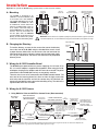
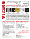
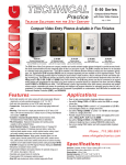
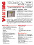
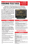
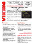
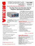
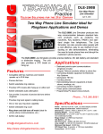
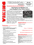
TECHNICAL
Practice
Practice
TELECOM SOLUTIONS
FOR THE
K-1205
K-1205-EWP
Multi-Button Handsfree
Entry Phone with Camera
2 1 S T C E N T U RY
December 30, 2013
12 Button Apartment Entry Phone with Built
in Door Strike Relay and Camera
The K-1205 Entry Phone is a two-way, handsfree telephone with 12 buttons for calling individual residences in an apartment building. It also has
a built-in color CCTV video camera. The rugged stainless steel faceplate
has a printed directory housed in a waterproof, scratch-resistant lens.
Each button is beside the tenants name in the directory so there are no
confusing codes to deal with. Calling a particular tenant is as easy as
pressing a single button. The K-1205 has a built in speed dialer that can
handle up to 12 primary phone numbers, each with 22 digits. If there is
no answer at the first number, a second number can be called automatically. Once the tenant answers their phone, a single touch tone command
can activate the door strike relay. For “no phone line” applications, the K1205 is compatible with the C-3000 no CO (phone line) controller. The
high resolution video camera is mounted on an adjustable bracket so it
can be positioned just right to view the outside visitor.
Model K-1205 (shown in optional
VE-5x10-SS, not included)
The K-1205-EWP shares all of the features of the K-1205 in addition to
Enhanced Weather Protection (EWP) for outdoor installations where the
unit is exposed to precipitation or condensation. EWP products feature
foam rubber gaskets and boots, sealed connections, gel-filled butt connectors, as well as urethane or thermal plastic potted circuit boards with
internally sealed, field-adjustable trim pots and DIP switches for easy onsite programming.
Features
Applications
• Vandal Resistant Features: 14 gauge louvered 316
stainless steel faceplate with permanent laser etched
graphics, stainless steel speaker/mic screen, heavy
duty metal keypad and hex drive mounting screws.
• Weather Resistant Features: Marine grade 316
stainless steel faceplate and screws. Internally sealed
keypad. Mylar speaker. Self-draining mic mount.
Faceplate, mic and speaker gaskets.
• K-1205-EWP is designed to meet IP66 Ingress
Protection Rating (see DOD# 859 for more information)
• Built-in high resolution color video camera with wide
viewing, tilt/swivel adjustments and wide operating
temperature of -30°F to 150°F
• Operates on 12 to 24 volts AC/DC
• 12 speed dial buttons (22 digits each)
• 12 alternate number positions (22 digits each)
• One button operation (no call button)
• Hang-up on CPC, busy, silence, time-out or dial tone
• Touch tone restriction from microphone
• Integral relays for camera control and door strike
• Works with C-1000B for increased security
• Works with C-3000 for “No CO” (phone line) operation
• 50 keyless entry codes and postal lock input
• Small apartment buildings
• Professional buildings
• Gated communities
Phone...715.386.8861
w w w. v i k i n g e l e c t r o n i c s . c o m
[email protected]
Specifications
Dimensions: 127mm x 254mm x 63.5mm (5" x 10" x 2.5")
Shipping weight: 2.5 kg (5.5 lbs.)
Operating Temp: -35°C to 66°C (-30°F to 150°F)
Relay Contact Rating:
Door Strike: 5A @ 30VDC/250VAC Maximum
Camera: 0.5A @ 125 VAC, 1.0A @ 30VDC
Connections: (13) gel-filled butt connectors (3M Scotchlok UR2)
(See page 2 for complete specifications)
IF YOU HAVE A PROBLEM WITH A VIKING PRODUCT, PLEASE CONTACT: VIKING TECHNICAL SUPPORT AT (715) 386-8666
Our Technical Support Department is available for assistance Monday 8am - 4pm and Tuesday through Friday 8am - 5pm central time. So that we can give you better service, before you call please:
1. Know the model number, the serial number and what software version you have (see serial label).
2. Have your Technical Practice in front of you.
3. It is best if you are on site.
RETURNING PRODUCT FOR REPAIR
RETURNING PRODUCT FOR EXCHANGE
The following procedure is for equipment that needs repair:
1. Customer must contact Viking's Technical Support Department at 715-386-8666 to obtain a Return Authorization (RA) number.
The customer MUST have a complete description of the problem, with all pertinent information regarding the defect, such as
options set, conditions, symptoms, methods to duplicate problem, frequency of failure, etc.
2. Packing: Return equipment in original box or in proper packing so that damage will not occur while in transit. Static sensitive equipment such as a circuit board should be in an anti-static bag, sandwiched between foam and individually boxed. All equipment
should be wrapped to avoid packing material lodging in or sticking to the equipment. Include ALL parts of the equipment. C.O.D.
or freight collect shipments cannot be accepted. Ship cartons prepaid to: Viking Electronics, 1531 Industrial St, Hudson, WI 54016
3. Return shipping address: Be sure to include your return shipping address inside the box. We cannot ship to a PO Box.
4. RA number on carton: In large printing, write the R.A. number on the outside of each carton being returned.
The following procedure is for equipment that has failed out-of-box (within 10 days of purchase):
1. Customer must contact Viking’s Technical Support at 715-386-8666 to determine possible causes for the problem. The customer
MUST be able to step through recommended tests for diagnosis.
2. If the Technical Support Product Specialist determines that the equipment is defective based on the customer's input and troubleshooting, a Return Authorization (R.A.) number will be issued. This number is valid for fourteen (14) calendar days from the
date of issue.
3. After obtaining the R.A. number, return the approved equipment to your distributor, referencing the R.A. number. Your distributor
will then replace the product over the counter at no charge. The distributor will then return the product to Viking using the same
R.A. number.
4. The distributor will NOT exchange this product without first obtaining the R.A. number from you. If you haven't followed
the steps listed in 1, 2 and 3, be aware that you will have to pay a restocking charge.
TWO YEAR LIMITED WARRANTY
Viking warrants its products to be free from defects in the workmanship or materials, under normal use and service, for a period of two years from the date of purchase from any authorized Viking distributor. If at any time during the warranty
period, the product is deemed defective or malfunctions, return the product to Viking Electronics, Inc., 1531 Industrial Street, Hudson, WI., 54016. Customer must contact Viking's Technical Support Department at 715-386-8666 to obtain a Return
Authorization (R.A.) number.
This warranty does not cover any damage to the product due to lightning, over voltage, under voltage, accident, misuse, abuse, negligence or any damage caused by use of the product by the purchaser or others. This warranty does not cover
non-EWP products that have been exposed to wet or corrosive environments. This warranty does not cover stainless steel surfaces that have not been properly maintained.
NO OTHER WARRANTIES. VIKING MAKES NO WARRANTIES RELATING TO ITS PRODUCTS OTHER THAN AS DESCRIBED ABOVE AND DISCLAIMS ANY EXPRESS OR IMPLIED WARRANTIES OR MERCHANTABILITY OR FITNESS
FOR ANY PARTICULAR PURPOSE.
EXCLUSION OF CONSEQUENTIAL DAMAGES. VIKING SHALL NOT, UNDER ANY CIRCUMSTANCES, BE LIABLE TO PURCHASER, OR ANY OTHER PARTY, FOR CONSEQUENTIAL, INCIDENTAL, SPECIAL OR EXEMPLARY DAMAGES
ARISING OUT OF OR RELATED TO THE SALE OR USE OF THE PRODUCT SOLD HEREUNDER.
EXCLUSIVE REMEDY AND LIMITATION OF LIABILITY. WHETHER IN AN ACTION BASED ON CONTRACT, TORT (INCLUDING NEGLIGENCE OR STRICT LIABILITY) OR ANY OTHER LEGAL THEORY, ANY LIABILITY OF VIKING SHALL
BE LIMITED TO REPAIR OR REPLACEMENT OF THE PRODUCT, OR AT VIKING'S OPTION, REFUND OF THE PURCHASE PRICE AS THE EXCLUSIVE REMEDY AND ANY LIABILITY OF VIKING SHALL BE SO LIMITED.
IT IS EXPRESSLY UNDERSTOOD AND AGREED THAT EACH AND EVERY PROVISION OF THIS AGREEMENT WHICH PROVIDES FOR DISCLAIMER OF WARRANTIES, EXCLUSION OF CONSEQUENTIAL DAMAGES, AND EXCLUSIVE REMEDY AND LIMITATION OF LIABILITY, ARE SEVERABLE FROM ANY OTHER PROVISION AND EACH PROVISION IS A SEPARABLE AND INDEPENDENT ELEMENT OF RISK ALLOCATION AND IS INTENDED TO BE ENFORCED
AS SUCH.
FCC REQUIREMENTS
This equipment complies with Part 68 of the FCC rules and the requirements adopted by the ACTA. On the side of this
equipment is a label that contains, among other information, a product identifier in the format US:AAAEQ##TXXXX. If
requested, this number must be provided to the telephone company.
The REN is used to determine the number of devices that may be connected to a telephone line. Excessive REN's on a
telephone line may result in the devices not ringing in response to an incoming call. In most but not all areas, the sum of
the REN's should not exceed five (5.0) To be certain of the number of devices that may be connected to a line, as determined by the total REN's, contact the local telephone company. For products approved after July 23, 2001, the REN for
this product is part of the product identifier that has the format US:AAAEQ##TXXXX. The digits represented by ## are the
REN without a decimal point (e.g., 03 is a REN of 0.3). For earlier products, the REN is separately shown on the label.
The plug used to connect this equipment to the premises wiring and telephone network must comply with the applicable
FCC Part 68 rules and requirements adopted by the ACTA. If your home has specially wired alarm equipment connected
to the telephone line, ensure the installation of this K-1205 does not disable your alarm equipment. If you have questions
about what will disable alarm equipment, consult your telephone company or a qualified installer.
If the K-1205 causes harm to the telephone network, the telephone company will notify you in advance that temporary discontinuance of service may be required. But if advance notice isn't practical, the telephone company will notify the customer as soon as possible. Also, you will be advised of your right to file a complaint with the FCC if you believe it is necessary.
The telephone company may make changes in its facilities, equipment, operations, or procedures that could affect the
operation of the equipment. If this happens, the telephone company will provide advance notice in order for you to make
the necessary modifications to maintain uninterrupted service.
If trouble is experienced with the K-1205, for repair or warranty information, please contact:
Viking Electronics, Inc., 1531 Industrial Street, Hudson, WI 54016 (715) 386-8666
If the equipment is causing harm to the telephone network, the telephone company may request that you disconnect the
equipment until the problem is resolved.
Connection to Party Line Service is subject to State Tariffs. Contact the state public utility commission, public service commission or corporation commission for information.
WHEN PROGRAMMING EMERGENCY NUMBERS AND (OR) MAKING TEST CALLS TO EMERGENCY NUMBERS:
Remain on the line and briefly explain to the dispatcher the reason for the call. Perform such activities in the off-peak
hours, such as early morning or late evenings.
It is recommended that the customer install an AC surge arrester in the AC outlet to which this device is connected. This
is to avoid damaging the equipment caused by local lightning strikes and other electrical surges.
PART 15 LIMITATIONS
This equipment has been tested and found to comply with the limits for a Class A digital device, pursuant to Part
15 of the FCC Rules. These limits are designed to provide reasonable protection against harmful interference
when the equipment is operated in a commercial environment. This equipment generates, uses, and can radiate radio frequency energy and, if not installed and used in accordance with the instruction manual, may cause
harmful interference to radio communications. Operation of this equipment in a residential area is likely to cause
harmful interference in which case the user will be required to correct the interference at his own expense.
Specifications
Entry Phone Specifications
Entry Phone / Camera Specifications
Dimensions: 127mm x 254mm x 63.5mm (5" x 10" x 2.5")
Operating Temp: -35°C to 66°C (-30°F to 150°F)
Shipping weight: 2.5 kg (5.5 lbs.)
Connections: (13) gel-filled butt connectors (3M Scotchlok UR2)
Power: 12 to 24V AC or DC, 12V DC adapter provided.
Note: To assure operation during a power outage, a UPS
should be used. Operating Temperature: -34° C to 65° C
(-30° F to 150° F)
Humidity: Standard model: 5% to 95% non-condensing,
EWP model: Up to 100%
Relay Contact Rating: Door Strike: 5A @ 30VDC/250VAC
Maximum, Camera: 0.5A @ 125 VAC, 1.0A @ 30VDC
Connections:
(13) gel-filled butt connectors (3M
Scotchlok UR2)
Recommended Surface Mount Box: Viking model VE5x10 (DOD# 424)
Camera Specifications
Power: 6-22V DC 150mA (12V DC UL Listed adapter included)
Image Sensor: 1/4” color CMOS
Video Output: 1 VP-P composite, NTSC, 75 ohms
Resolution: 420 lines (640 x 480 @ 30fps / 307,200 pixels)
Sensitivity: 0.025 LUX (50 IRE) F 1.2 3200K
Lens: 3.4mm, pinhole 70° FOV (Field of View)
Tilt/Swivel Adjustment: Vertical +/- 20°, horizontal +/- 30° (see Diagram A)
IR Compatibility: This camera is equipped with an OLP (Optical Low Pass)
filter to maintain correct video color in outside applications. The standard
camera is NOT compatible with IR illuminators. If IR illumination is required,
you will need to replace the exisiting camera with a Viking model VCAM-1IR.
For more information, see DOD# 190.
Maximum Wire Run Length: 1000 ft with *RG59/RG6 for video and CAT5
for power (1 pair) and entry phone audio (1 pair). 150 ft with CAT5E for video,
power and entry phone audio (longer video runs are possible by using video
balun transceivers, see Installation section F, page 5). * Note: RG59
or RG6 with solid center conductor and 95% bare copper braid shield.
2
Diagram A
70° Lens FOV
Rotate
Left 30°
Rotate
Right 30°
Camera Lens
Installation
Important: To operate the K-1200 during a power failure, a UPS should be installed.
Front View
of the K-1205
A. Mounting
The K-1205 is designed to be
installed in a sheltered location, and
is not meant to be used outdoors.
For outdoor applications use the K1205-EWP. The K-1205 can either
be installed as a flush mount unit
using the included rough in box, or
as a surface mount unit using an
optional VE-5x10. The rough in box
uses the inner set of four holes on
the face plate while the VE-5x10
uses the outside set of holes. A set of
dummy screws and nuts are provided to fill the unused mounting holes.
5.00"
4.50"
2.596"
0.952"
10.0"
2
Zinc-Plated Steel
Rough-In Box (included)
4.5"
Optional VE-5x10 Surface
Mount Box (not included),
see DOD# 424
2.5"
3.69"
5.22"
0.425"
8.65"
1
9.5"
Side View
of the K-1200
3
4
(8) #6-32 x 3/4"
Marine Grade
Stainless Steel
Flathead, 5/64"
Hexdrive Screws
(included)
- or 9.12"
10.14"
5
6
7
8
9
0
*#
VIKING
©
14 Gauge Marine Grade 316
Stainless Steel Faceplate
IMPORTANT: Electronic devices are susceptible to lightning and power station electrical surges from both the AC
outlet and the telephone line. It is recommended that a surge protector be installed to protect against such surges.
!
Paper Directory
B. Changing the Directory
Directory
Lens
To install a directory, remove the four screws that mount the directory
lens to the front of the K-1205 using the included Allen wrench. Insert
a paper directory behind the lens and secure the two back onto the
front panel being careful to align the names with the front panel graphics. For your convenience, the back of this document has pre-printed
directory forms.
C. Wiring the K-1205 Controller Board
The K-1205 can be powered from any source supplying 12 to 24 volts, AC or
DC. A 12 volt DC adapter is supplied with the product. When using the included adapter, the plug on the adapter cord will have to be removed. The power
connections to the K-1205 (black wires) are not polarity sensitive.
There are also 8 more wires connected to the K-1205 controller board. Two
wires are for the incoming phone line, three are from the high current door
strike relay and the last three are from the camera relay. Gel filled butt connectors are provided for easier connection to building wiring. The table at the
right describes each wire’s function.
Color
Black
Black
Green
Red
Brown
Orange
Yellow
Blue
Violet
White
Function
Power In
Power In
Phone Line In
Phone Line In
Door Strike Relay common
Door Strike Relay NC
Door Strike Relay NO
Camera Relay common
Camera Relay NC
Camera Relay NO
D. Wiring the K-1205 Camera
1. Using RG59 for Video and CAT5 for Camera Power (Recommended)
3-Wire Gel-Filled Butt
Connectors included
(3M Scotchlok UR2)
Back View of
the K-1205
Center conductor
stripped back 5/8"
*** RG59 or RG6 Shielded
Video Cable, up to 1000 ft
"F"
Connector
"F" to Phono Plug
Adapter (Radio
Shack part #278-252)
Yellow (Video)
Twisted foil and braided shield
OR
Yellow/Red
Black
**** Female "F" to Wire or "BNC" to Wire
Converter Cable (not included)
- Black (GND)
** Camera GND (-)
**** For ease of installation, a Viking Female
"F" to Wire Converter Cable can be used (Part
# 261217) or "BNC" to wire converter cable
(Part # U213510) can be used. Go to
www.vikingelectronics.com and click on
"Spare Parts" to order.
CAT5 Cable
W/O
W/O
VIKING
Orange
Model: xxxxxxxxx
S/N: XXXXXX
P/N: xxxxxxxxx DEV:
Viking Electronics, Inc. (715)386-8861
1531 Industrial St., Hudson, WI 54016
RoHS
+ Red (12VDC)
** Camera Pwr (+) Orange
** Up to 1000 ft
!
To unused input on TV,
VHF modulator, whole
house video distribution
equipment, IP video
encoder (Axis M7001), etc.
12V DC Adapter
(included)
Camera GND (-)
(-)
-
Camera Power (+)
!
120V AC
(+)
+
(4) Crimp-on Splice
Connectors (not included)
IMPORTANT: Electronic devices are susceptible to lightning and power station electrical surges from both the AC outlet and the telephone line.
It is recommended that a surge protector be installed to protect against such surges.
3
2. Using CAT5E or CAT6 for Video and Camera Power (see Caution below)
To unused input on TV, VHF
modulator, whole house video
distribution equipment, IP video
encoder (Axis M7001), etc.
Back View of
the K-1205
(+)
Video GND (-)
W/G
Yellow (Video)
- Black (GND)
Video Out (+)
Video GND (-)
VIKING
Model: xxxxxxxxx
S/N: XXXXXX
P/N: xxxxxxxxx DEV:
RoHS
+ Red (12VDC)
12V DC Adapter
(included)
(see Caution below)
Green
W/O
W/O
Phono (RCA) Plug,
F Connector, Etc.
Green
CAT5E or
CAT6 Cable
W/G
** Camera GND (-)
Viking Electronics, Inc. (715)386-8861
1531 Industrial St., Hudson, WI 54016
(-)
Video Out (+)
3-Wire Gel-Filled Butt
Connectors included
(3M Scotchlok UR2)
Orange
(-)
Camera GND (-)
-
!
120V AC
(+)
+
Camera Power (+)
** Camera Pwr (+) Orange
* Up to 150 ft
(4) Crimp-on Splice
Connectors (not included)
* Note: Up to 150 ft video cable run length can be achieved using CAT5E or CAT6 cable. Longer cable runs can be used if a passive or active video Balun transceiver is used on
each end of the cable. Generally, passive transceivers can achieve up to 750 ft cable runs where active transceivers can achieve up to 3000 ft runs depending on cable type, etc.
The type of video balun transceiver required is specific to your cable run length. For more information on video balun transceivers go to: www.northernvideo.com.
** Note: The maximum camera power supply wire run length is 1000 ft of 24 gauge wire (CAT 5/6), longer runs are possible by doubling pairs, increasing the wire gauge or
using up to a 22V DC 200mA power adapter.
*** Note: RG59 or RG6 with solid center conductor and 95% bare copper braid shield.
Caution: When routing CAT5E or CAT6 cable, maintain a minimum distance of 3 ft from any parallel high voltage wire (110 VAC) and a minimum of 2 ft from crossing any high voltage wire. For installations where RF noise is expected (commercial applications) or wire runs are near high voltage (110 VAC) wires, a shielded video cable such as RG6 is recommended.
Applications
A. Connecting a Doorstrike to the K-1205 Internal Relay
The K-1205 provides a dry contact output that
can be used for operation of a door strike. To
use this feature, the Door Strike Code and
Door Strike Time must be set in programming.
In this mode, when the Door Strike Code is
detected, the K-1205 will energize the relay for
the period of time selected in the Door Strike
Time (see Programming section E and F).
* Note: To prevent unwanted radio interference, route
the connecting wires through the included ferrite core.
Black
Black
120V AC
Red
* Ferrite Core
(included)
CO Line
Green
Brown (COM)
Doorstrike/Magnetic Lock
Yellow (N.O.)
Orange (N.C.)
VIKING
If a Postal Lock is required, connect the normally open contacts of the lock to the two
white wires coming from the two pin connector
on the lower portion of the control board.
When the postal lock is momentarily actuated,
the door strike will energize for the programmed Door Strike Time.
120V AC
Model: xxxxxxxxx
S/N: XXXXXX
White
RoHS
P/N: xxxxxxxxx DEV:
Viking Electronics, Inc. (715)386-8861
1531 Industrial St., Hudson, WI 54016
Postal Lock
Switch (N.O.)
White
Rear View
of the K-1205
** Gel-Filled Butt Connectors (included)
** Note: The gel-filled (water-tight) butt connectors are designed for insulation displacement on 19-26 gauge wire with a maximum insulation of 0.082 inches. Cut off
stripped ends prior to terminating.
120V AC
B. Connecting Camera Control to the K-1205 Internal Relay
Another internal relay in the K-1205 can be used to
trigger a camera controller. When the K-1205
makes a call, it will energize the relay and hold it on
until the call is done.
Black
Black
Red
* Ferrite Core
(included)
* Note: To prevent unwanted radio interference,
route the connecting wires through the included
ferrite core.
4
Blue (COM)
Camera
Controller
Violet (NC)
White (NO)
VIKING
** Note: The gel-filled (water-tight) butt connectors
are designed for insulation displacement on 19-26
gauge wire with a maximum insulation of 0.082
inches. Cut off stripped ends prior to terminating.
CO Line
Green
Model: xxxxxxxxx
S/N: XXXXXX
(not included)
or
RoHS
P/N: xxxxxxxxx DEV:
Viking Electronics, Inc. (715)386-8861
1531 Industrial St., Hudson, WI 54016
Rear View
of the K-1205
** Gel-Filled Butt
Connectors (included)
C. Using the K-1205 with a C-1000B
Model C-1000B (not included)
120V AC
In some instances it may be a concern
that the Door Strike relay is outside the
door. In this situation, a second controller
such as a C-1000B can be used. Be sure
to disable the door strike code for the K1205 (see Programming section G).
Notes: 1. The C-1000B must be in the
“Analog Station Mode” (refer to the C1000B Technical Practice). 2. The K1205’s keyless entry code can not be
used in this application. 3. The K-1205
will hang-up during door strike activation.
VIKING ©
MODEL C-1000B
Talk Battery Switch
ELECTRONICS
HUDSON, WI 54016
2
3 4
5
COM
7
DIP Switches
ON
ON
1
N.O. N.C. - - - - AUX.
CONTACT
OUTPUT
2
OFF
3
ON
C
LED1
OUT TO
PHONES
ON
9 10 11 12 13 14 15 16 17 18 19
8
SIG GND SIG GND SIG GND
VIDEO 1 IN VIDEO 2 IN VIDEO OUT
EARTH C.O. LINE
GND
INPUT
DOOR
STRIKE 2
DOOR
STRIKE 1
DOORBOX 2
DOORBOX
PWR OUTPUT
KEYLESS CONTACT
CLOSURE INPUT
6
DOORBOX 1
LINE OUT
TO PHONES
PWR 13.8 VAC
EARTH
GND
1
OFF
DOOR ENTRY / CCTV VIDEO
CONTROLLER
PHONE LINE
INPUT
13.8V AC
Adapter
(included)
KEYLESS
C.C. INPUT
TALK
OFF
DOOR
BOX 1
DOORBOX
13VAC PWR
C
LED2
BATTERY
ON
DOOR
BOX 2
1
2
3
C
LED3
120V AC
N.O. COM N.C.
DOOR STRIKE 1
N.O. COM N.C.
DOOR STRIKE 2
Doorstrike/Magnetic Lock 2
* Earth
Ground
5A@30V DC/
250V AC maximum
120V AC
Red
CO line or Analog
PABX/KSU Station
Green
1
2
3
4
5
6
7
8
9
0
*#
VIKING
Model
K-1205
©
D. Using the K-1205 with a C-3000
For a “No CO” installation, a Viking C-3000 No
CO controller can be used with the K-1205.
Note, the K-1205 will need to be programmed
on a separate CO line or use the Viking DLE200B. The door strike can be controlled by the
K-1205 or the internal relay on the C-3000, just
be sure to disable the door strike feature in the
other unit. The keyless entry feature of the C3000 can not be used. If not using keyless entry
codes, use the C-3000 to control the doorstrike.
If using keyless entry codes (up to 50), use the
K-1205 to control the doorstrike. The K-1205
speed dial position should be programmed with
the C-3000 line selection command “1” to “12”.
(Refer to the C-3000 Technical Practice for
more details).
VIKING ©
MODEL C-3000
Model C-3000
(not included)
VIKING
ELECTRONICS
HUDSON, WI 54016
12 UNIT APARTMENT
ENTRY CONTROLLER MODULE
POWER
13.8 VAC
120V AC
POSTAL
LOCK
INPUT
DIP
SWITCH
1 2 3
DOOR
STRIKE
1
DOOR
STRIKE
2
MULTI-MODULE
INTERCONNECTS
O
F
F
2
RJ21X
12 APARTMENT LINES IN/OUT
1 2 3 4 5 6 7 8
O
N
1
3
PWR
4
IN
USE
5
6
PROGRAM PHONE
7
2
3
5
ENTRY
PHONE 2
OUT
IN
6
7
8
9
9
0
Red
Green
Green
Red
*#
VIKING
1
4
ENTRY
PHONE 1
8
Model
K-1205
120V AC
©
0
*#
VIKING
©
Model
K-1205
Notes: 1. In this application, the C-3000 keyless entry feature is not available.
Use the keyless entry feature of the K-1205 and wire both door strike relays in
parallel. 2. The K-1205 will hang-up during the doorstrike activation.
Programming
A. Accessing The Programming Mode
The K-1205 Entry Controller can be programmed from any Touch Tone phone using a C.O. line, analog PABX/KSU,
or a DLE-200B Line Simulator.
1. Accessing the Programming Mode with the Security Code
Step 1.
Move DIP switch 1 to the ON position (sets unit to answer incoming calls).
Step 2.
From a touch tone phone, call the line attached to the K-1205.
Step 3.
When the K-1205 answers, listen for the beep and then enter a “#“ followed by the 6-digit security code (factory
set to 845464). A double beep should be heard indicating you have entered the programming mode.
2. Accessing the Programming Mode without the Security Code
Step
Step
Step
Step
Step
1.
2.
3.
4.
5.
Move DIP switch 1 to the ON position (sets unit to answer incoming calls).
Move DIP switch 4 to the ON position (incoming calls enter programming without security code, see section B).
From a touch tone phone call the line attached to the K-1205.
When the K-1205 answers, a double beep should be heard indicating you have entered the programming mode.
When finished programming, move DIP switch 4 back to the OFF position.
5
B. Security Code (memory location #47)
This six digit number can be used to access the programming mode. The security code has been factory set to 845464 (V-I-K-I-NG). It is recommended that you change the security code to a personal 6 digit number. To change the security code, access programming (see Programming section A). Enter six digits 0-9 followed by #47. If you have forgotten your security code, follow the
steps in Programming section A, 2. Accessing the Programming Mode Without the Security Code). Note: The security code
must be six digits in length and can NOT contain a Q or #.
C. Keyless Entry Codes
The K-1205 can be programmed with up to 50 keyless entry codes. This feature allows a visitor to let themselves in by entering a
preprogrammed code on the K-1205 keypad. Each keyless code can contain from 1 to 6 digits and is programmed by entering the
digits into any of the locations #50 to #99. To clear a location enter “#” followed by the position number without any preceding number. The “Q” and “#” keys can also be used in the keyless codes by substituting “#20” and “#21” (respectively) when programming
a keyless position.
D. Quick Programming Features
The K-1205 is programmed through the incoming phone line. The programming commands are structured so that they do not
interfere with the commands of a C-1000B controller.
Enter Digits - then - Enter Memory Location
Speed dial numbers .................................................................................................. 0-46 digits*** then
#01 - #12
Door strike time in sec (factory 05, 00 =.5 sec)**........................................................ 2 digits
#40
then
Door strike code (factory 6, no digits disables) .......................................................... 1-2 digits
#41
then
Maximum call time in min (factory 3, 0 = .5 min, no digits disables)** ....................... 1 digit
#42
then
Maximum ring time in sec (factory 20, 00 disables)** ............................................... 2 digits
#43
then
Silence Time Out in sec (factory 10, 00 disables)** .................................................. 2 digits
#44
then
Talk/listen delay time in .1 sec (factory 2)** ............................................................... 1 digit
#45
then
Security code (factory 845464)** ............................................................................... 6 digits
#47
then
Keyless entry codes .................................................................................................. 1-6 digits
#50 - #99
then
Dial a (Q) .................................................................................................................. #20
Dial a (#) ................................................................................................................... #21
Add a 4 second pause .............................................................................................. #22
Add a 1 second pause ............................................................................................. #23
Second phone number selector ................................................................................ #24 *Factory settings
Normal dialing speed* .............................................................................................. #30 ** Cannot contain “Q“ or “#“ (see #20 and #21)
*** 45 digits maximum if two numbers are proFast dialing speed ..................................................................................................... #31
grammed in one memory location
Hang up on dial tone enable* ................................................................................... #32 Notes: 1. A single or double beep indicates a
Hang up on dial tone disable .................................................................................... #33 valid entry, three beeps indicate an error. 2.
Reset all programming to factory default settings ................................................... ### “Q“ or “#“, pauses or second phone number
selector occupy one digit of memory.
Hang up from programming ...................................................................................... ##7
E. Speed Dial Numbers
The K-1205 Entry Controller can be programmed with up to twelve 46 digit numbers. Each number can also be programmed with
special features such as pauses, and the Touch Tones “Q” and “#”. Each of the special characters count as a single digit. Each of
the speed dial positions #01 to #12 pertain to the corresponding button on the front of the K-1205. The button “0” uses position #10,
the “Q” uses position #11 and the “#” uses position #12. To program a speed dial position, enter programming (see section A) then
enter the desired number followed by the selected position. To clear a position, only enter a “#“ followed by the position number with
out any preceding number. The K-1205 also has the capability to dial a second phone number if there is no answer or busy at the
first number. This can be used if the tenant wants the visitor to call their cell phone if they are not at home. To program a second
number, be sure that position #43 is programmed with the desired maximum ring time, then enter the first number to be dialed, followed by “#24”. A single beep should be heard. Next enter the second number to be dialed followed by “#“ plus the memory location. The total number of digits cannot exceed 46 for each position (45 digits if two numbers are programmed).The following are
examples of speed dial number entries:
To Program the K-1205 to...
Step 1 (see section A)
Step 2 - Enter Digits
...store 555-1234 at the first button position
Enter programming
5551234#01
...store a 9, a 1 second pause, then 333-4444 in the seventh button position
Enter programming
9#233334444#07
...store a 23Q# in the eight position
Enter programming
23#20#21#08
...store a first number of 22 and a second number of 33 in the “#“
button position
Enter programming
22#24 (beep) 33#12
F. Door Strike Time
The actual time the door strike relay is energized is controlled by location #40. The time can be set from 00 to 99 seconds, (an entry
of “00” gives 0.5 seconds). In order to use this feature, be sure the relay door strike code is set (see section G).
6
G. Door Strike Code
A one or two digit door strike code can be entered by programming position #41. When in programming, enter the one or two digit
code followed by “#41”. Note: “Q” and “#” can be entered as valid characters of the door strike code by substituting “#20” and #21”
(respectively) when programming the door strike code (see section D). To disable the door strike relay, enter “#41” without any preceding numbers. The following are examples of door strike code entries:
To Program the Door Strike Code to...
Step 1 (see section A)
Step 2 - Enter Digits
”99”
Enter programming
99#41
”3”
Enter programming
3#41
”QQ”
Enter programming
#20#20#41
”#1”
Enter programming
#211#41
H. Maximum Call Time
In some installations, it maybe desirable to limit the length of the call to the tenant. This can be done by programming position #42.
The maximum call time can be set from 1 minute to 9 minutes by entering the appropriate number in position #42. A “0” will yield a
30 second time. To disable the call timer enter “#42” without any preceding digit.
I. Maximum Ring Time
This timer sets the maximum amount of time the K-1205 will look for the call to be answered. If this timer expires and the tenant has
not answered, the call will be terminated or the K-1205 will dial the second phone number (if programmed). The factory setting is
20 seconds, and to disable this feature, enter “00” into position 43.
J. Silence Time Out
This time out is started once the call has been connected and is reset every time audio is detected on the phone line. If it expires,
the call will be terminated. This is useful on systems that are silent when the tenant hangs up to assure the K-1205 disconnects. It
is factory set to 10 seconds and can be disabled by entering “00” in position 44.
K. Talk/Listen Delay
This time represents the amount of time the K-1205 will delay before switching back to the microphone mode after it was in the
speaker mode (VOX switching time). It is in 100 msec increments and stored in position 45.
L. Dialing Speed
On some phone lines, a faster rate of dialing is allowed. The dialing speed of the K-1205 can be altered to take advantage of this
faster rate. The normal dialing speed is 5 digits per second and is selected by entering “#30” (factory setting) while in programming.
To increase the speed to 10 digits per second, enter “#31”. If the faster rate is selected, be sure to test each number to assure proper operation.
M. Hang Up on Return to Dial Tone
The K-1205 is factory set to hang up if continuous audio is detected after dialing. In most situations this would happen if the tenant
hung up and the service that the K-1205 is connected to provides a dial tone following the hang up. In some instances due to noisy
lines or loud background noise, the call may be terminated before the tenant hangs up. If this occurs, enter “#33” when in programming. This will disable return to dial tone feature and stop the K-1205 from hanging up prematurely. To enable this feature enter “#32”
when in programming.
N. Special Commands
To clear all speed dial positions and set all modes back to factory setting, enter “###“ while in programming. Caution, all previous
programming will be lost. Normally when the K-1205 is in the programming mode, it will hang up the line if no commands are detected for 20 seconds. To hang up immediately, enter “##7”.
O. DIP Switch Programming/Speaker and Microphone Adjustments
Two POTs are provided to increase or decrease speaker volume and microphone sensitivity. In certain noisy locations the microphone sensitivity may need to be decreased as shown below. Caution: Setting the microphone gain too high may cause distorted audio, prevent the distant party from breaking over and inhibit second number redialing.
Switch Position
Description
1
ON
Incoming calls answered (factory setting)
1
OFF
Incoming calls not answered
2&3
ON
Audio Detection normal (factory setting)
2&3
OFF
Audio Detection more sensitive
4
ON
Learn Mode - Any incoming calls are automatically entered into the programming mode,
no security code required. Use this option if
you have forgotten your security code.
OFF
Normal operation mode (factory setting)
4
Turn POTS clockwise to increase
(as viewed from the back of the board)
Microphone
Sensitivity POT
ON
OFF
Speaker
Volume POT
on
1
2
3
4
1 2 3 4
Note: On some phone lines, busy and
ring back tones maybe very soft. In
these installations, set DIP switches 2
and 3 to the OFF position.
7
Operation
When a visitor is at the K-1205, they just need to find the name of the tenant they want to visit on the directory and press the associated button. The K-1205 will then seize the phone line and speed dial the number programmed for that name. When the tenant answers
the call, they can let the visitor in by entering the Door Strike Code on their telephone keypad. The tenant can converse with the visitor
for up to 10 seconds after the Door Strike Code is dialed (to verify the visitor has been granted entry). The K-1205 is able to determine
if the door strike command is coming from the apartment or the caller, to prevent entry using a hand held touch tone dialer. If the tenant
chooses not to let the visitor in, they can simply hang up the phone. The K-1205 will drop the line when busy, reorder, CPC signals are
detected, when programmable maximum call time out, silence time out, maximum ring timers expire or 10 seconds after a door strike
activation. Only the buttons that have a programmed phone number are active (except “#” when used for keyless entry). After a button
is pressed, and the call is initiated, it can be canceled by momentarily pressing any button on the panel.
If a second number is programmed for the selected tenant, and there is no answer or busy after dialing the first number, the K-1205 will
hang-up, pause, seize the line, and then dial this second number. In this manner the call can be routed to a cell phone if the tenant is not
at home. The tenant can still let the visitor in using the Door Strike Code.
It is also possible to talk to a visitor before they press a directory button. Make sure DIP switch 1 is on (Auto Answer, see section O) and
then call the phone number of the K-1205. The K-1205 will answer the ringing line and send a single beep. At this time the user is free
to converse with the visitor. For security reasons, the tenant is blocked from operating the door strike in this mode.
To use the keyless entry feature, momentarily press or press and hold the “#“ key on the K-1205 keypad. When momentarily pressed, 1
beep will be heard and if held for 2 seconds (or longer), 2 beeps will be heard. In either case, the K-1205 is then ready to accept the keyless code. Continue by entering one of the previously programmed keyless codes. The K-1205 will pause a few seconds to make sure
there are no more keypad entries, and then actuates the Door Strike relay if valid. If an incorrect code is entered, the K-1205 will beep 3
times and the user has to start over and enter a correct code.
If a Postal Lock is used, a momentary closure of the postal lock switch will energize the door strike for the programmed Door Strike Time.
Directory Forms
Product Support Line...715.386.8666
Fax Back Line...715.386.4345
Due to the dynamic nature of the product design, the information contained in this document is subject to change without notice. Viking Electronics, and its affiliates and/or subsidiaries assume no responsibility for errors and omissions contained in this information. Revisions of this document or new editions of it may be issued to incorporate such changes.
8
DOD# 183
Printed in the U.S.A.
ZF302650 Rev E