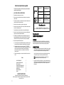
1
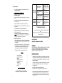
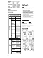
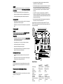
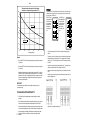
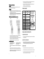
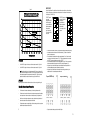
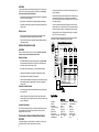
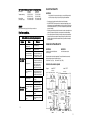
PowerStream Pro
GARANTÍA LIMITADA DE 10 AÑOS (continuación de la Página 11)
3.
Verificación de la fecha de instalación original: cuando el propietario no puede verificar o
documentar la fecha de instalación original, el período de garantía se inicia en la fecha de
fabricación marcada en la etiqueta fijada al calentador de agua.
EXCLUSIONES
1.
ESTA GARANTÍA LIMITADA SERÁ LA GARANTÍA EXCLUSIVA DEL FABRICANTE Y EXCLUYE
TODAS LAS DEMÁS GARANTÍAS EXPRESAS O TÁCITAS (POR ESCRITO O DE PALABRA),
INCLUYENDO, ENTRE OTRAS, LAS GARANTÍAS DE COMERCIABILIDAD O IDONEIDAD PARA
UN FIN DETERMINADO.
2.
El fabricante no se responsabilizará de los daños imprevistos, resultantes, especiales o
contingentes, ni de los gastos que surjan directa o indirectamente de los defectos en el calentador
de agua o de su uso.
3.
El fabricante no se responsabilizará de los daños producidos por el agua que surjan directa o
indirectamente de los defectos en los componentes del calentador de agua o de su uso.
4.
El fabricante está exento de responsabilidad bajo esta garantía si:
a)
El calentador de agua o cualquiera de sus componentes se ha sometido a una mala
utilización, alteración, negligencia o accidente, o
b)
El calentador de agua no se ha instalado en conformidad con la normativa y/o el reglamento
local aplicable de fontanería y/o vivienda, o
c)
El calentador de agua no se ha instalado en conformidad con las instrucciones impresas del
fabricante, o
d)
No existe un suministro continuo de agua potable en el calentador de agua.
5.
El propietario, y no el fabricante o su representante, se responsabilizará y pagará todos los daños
producidos por la mano de obra u otros gastos contraídos en el desmontaje y/o reparación del
equipo o daños producidos por el propietario a fin de reparar el equipo.
ALGUNOS ESTADOS NO PERMITEN QUE SE ESTABLEZCAN EXCLUSIONES O LIMITACIONES
DE DAÑOS IMPREVISTOS O RESULTANTES, POR LO QUE ES POSIBLE QUE LA ANTEDICHA
LIMITACIÓN NO LE SEA DE APLICACIÓN A USTED. ESTA GARANTÍA LE CONCEDE DERECHOS
JURÍDICOS ESPECÍFICOS, Y ES POSIBLE QUE USTED TENGA OTROS DERECHOS.
IMPORTANTE: EL PROPIETARIO DEBE GUARDAR ESTE CERTIFICADO
NOTA: La instalación de un calentador de agua se debe realizar de tal forma que, en caso de
pérdidas, el caudal de agua resultante no producirá daños en el área donde se instale.
La persona que instaló inicialmente la unidad es la más adecuada para proporcionar ayuda.
También puede llamar al número de teléfono de llamada gratuita de BBT 800-798-8161. Tenga a mano
esta guía cuando llame.
555-2028-03A
12.14.05
© 2005 Bosch Water Heating
Waitsfield, VT reservados todos los derechos
BBT NORTH AMERICA
Bosch Group
www.boschpro.com
Existen restricciones en las
tuberías de fontanería.
Important Safety Instructions
When using this electrical equipment, basic safety precautions should always be
followed, including the following:
Caudal de agua
demasiado bajo
1. READ AND FOLLOW ALL INSTRUCTIONS.
2.
This appliance must be grounded.
3.
Disconnect this product from the elect rical supply before cleaning, servicing or removing the
cover.
4.
To reduce the risk of injury, close supervision is necessary when the product is used near
children or elderly persons.
5.
Warning: Do not install the heater in a location where it may be subjec t to freezing.
6.
Warning: Do not install a check valve or any other type of back flow preventer within ten feet of
the cold water inlet.
7.
The electrical installation must conform to current National Electrical Codes.
8.
Warning: Do not switch the heater on if you suspect that it may be frozen. Wait until you are
sure that it has completely thawed out.
9.
The Powerstream Pro is designed to heat potable cold water for domestic purposes. The
maximum inlet water temperature it can handle is 86 degrees F. Contact Bosch Water Heating
before specifying or installing the appliance in any other application.
10. Additional Canadian safety instructions:
a)
As per the Canadian Electrical Code, C22.1-02 Section 26-744, an auxiliary terminal block
must be fitted to the unit before connecting to the electrical supply (Kit Part N° "AE Canada
Kit"). (See Page 6).
b)
A green terminal (or a wire connector marked “G,” “GR,” “GROUND” or “GROUNDING”) is
provided within the control. To reduce the risk of electrical shock, connect this terminal or
connector to the grounding terminal of the electrical service of supply panel with a
continuous copper wire in accordance with the Canadian Electrical Code, Part I.
c) This product shall be protected by a Class A ground fault circuit interrupter.
Presión de suministro de agua
demasiado baja.
Las válvulas de cierre de salida
tienen un ajuste demasiado
bajo.
La temperatura
del agua fluctúa
Fluctuación en la presión del
agua o en el caudal
Compruebe la fontanería. Utilice
sólo cinta de teflón para sellar las
juntas de las tuberías. Compruebe y
limpie la pantalla del filtro de aire en
el calentador.
Compruebe que las válvulas de
cierre de entrada están totalmente
abiertas.
Ajuste las válvulas de cierre de
salida según se describe en la
sección "Ajuste del caudal" (véase la
Página 8).
Evite utilizar al mismo tiempo varias
salidas de agua caliente, ya que
esto puede ocasionar fluctuaciones
en la temperatura.
Si el problema no se soluciona
La persona que instaló inicialmente la unidad es la más adecuada para proporcionar
ayuda.
También puede llamar al número de teléfono de llamada gratuita de BBT 800-798-8161. Tenga a
mano esta guía cuando llame.
PowerStream Pro
GARANTÍA LIMITADA DE 10 AÑOS
COBERTURA
APPLIED ENERGY PRODUCTS, A TRAVÉS DE SU DISTRIBUIDOR EN LOS EE.UU., BOSCH WATER
HEATING (en lo sucesivo denominado BBT) garantiza este calentador de agua al propietario
original del mismo y en la ubicación de instalación original contra defectos en los materiales y en la
fabricación durante el período de tiempo indicado a continuación.
Contents
Using the Powerstream Pro
Installing the Powerstream Pro
Spare Parts
Starting up the Powerstream Pro
How the Powerstream Pro works
Specifications
If you have a problem
Warranty
3
3
7
7
8
9
10
11
PERÍODO DE GARANTÍA
1.
Sin embargo, si el calentador de agua se instala en otra ubicación distinta de una vivienda familiar
individual, esta garantía está limitada a dos (2) años a partir de la fecha de la instalación y
funcionamiento originales.
Nota: La garantía no cubre los daños ocasionados por congelación.
Nota: La garantía no cubre los daños ocasionados por la formación de incrustaciones.
SAVE THESE INSTRUCTIONS
Keep this guide in a safe place once your unit has been installed.
You may need to refer to it for general instructions or future maintenance.
2
Intercambiador de calor: si existen pérdidas o fallos en el intercambiador de calor antes de los diez
(10) años a partir de la fecha de instalación original del calentador de agua que estén ocasionados
por un defecto en el material o la fabricación, BBT proporcionará al propietario un nuevo calentador
del modelo actual equiparable.
2.
Otros componentes que no sean el intercambiador de calor: si otro componente (que no sea el
intercambiador de calor) presenta defectos en el material o la fabricación antes de un (1) año a
partir de la fecha de instalación original del calentador de agua, BBT proporcionará al propietario
nuevos componentes.
11
Nota: La unidad puede funcionar con voltajes de suministro inferiores, pero se aplicarán los
cambios siguientes:
Potencia máxima
15kW a 220V
22,5kW a 220V
13kW a 208V
20kW a 208V
Intervalo de control de temperatura
30,5ºC hasta 46,6ºC a 220V
30,5ºC hasta 46,6ºC a 220V
27,7ºC hasta 42,2ºC a 208V
27,7ºC hasta 42,2ºC a 208V
Caudal máximo
84% del máximo a 220V
84% del máximo a 220V
(Consulte el Gráfico 1, Página 8)
75% del máximo a 208V
75% del máximo a 208V
ADVERTENCIA
Apague siempre el suministro eléctrico en la unidad antes de retirar la tapa.
Using the Powerstream Pro
WARNING
Do not use the unit if you think it may be frozen, as this could result in ser ious damage to the unit. Wait
until you are sure that it has completely thawed out before you switch it on.
•
•
Solución de problemas
•
La reparación sólo debe ser realizada por personal cualificado
Síntoma
Causa
No hay electricidad o hay un fallo en
uno de los suministros.
El suministro de agua está
conectado en la salida de la unidad.
Se ha disparado uno o varios
disyuntores del módulo calefactor.
Únicamente
agua fría –
luz neón
apagada
Cruce en las tuberías de fontanería.
El transductor de caudal no
funciona.
El caudal de agua es
demasiado alto.
Uno de los suministros eléctrico
no está encendido.
Agua
demasiado fría –
luz neón
encendida
10
Disminución del voltaje de
suministro eléctrico.
Acción
•
•
Check that the power is switched on at the circuit breaker panel.
Turn on the hot water faucet FULLY. The hot water temperature can be changed by adjusting the
temperature dial on the bottom surface of the unit. (The dial adjusts the temperature typically
between 95°F and 131°F. The factory sets the temperature dial at the lowest position.)
There are internal safety thermal cut-outs which will operate if the unit overheats. If a thermal cutout trips, then it must be reset by a qualified electrician.
If the unit has been used recently, run the water through for a few seconds to let the temperature
settle down. You may initially get a short burst of very hot water from the unit.
If a second outlet connected to the unit is also turned on, the hot water will be shared between the
two.
Compruebe el suministro eléctrico.
Vuelva a conectar el suministro de agua
en la entrada de la unidad (marca azul).
Apague el suministro eléctrico, abra la
unidad y reajuste presionando el botón
situado en la parte superior del módulo
calefactor. Averigüe y solucione la
causa del sobrecalentamiento.
Realice una comprobación cerrando el
suministro de agua del calentador, luego
abra la(s) llave(s) de agua caliente. No
debe existir caudal de agua presurizado.
Si hay agua, debe corregirse el cruce en
las tuberías de fontanería para que
funcione el calentador.
Desconecte el suministro eléctrico, abra
la unidad y observe si el transductor de
caudal "gira" cuando se abre el agua.
En caso contrario, póngase en contacto
con BBT en el número de llamada
gratuita 800-798-8161.
Installing the Powersteam Pro
WARNING
IMPORTANT
Do not install the unit in a room where there
is a chance of freezing.
Read entire instructions.
Check the pressure of the main water supply. To operate correctly, the unit needs the following running
pressures : Minimum: 15 psi (1 Bar)
Maximum: 150 psi (10 Bar)
Securing the unit to the wall
Diagram 1
RP17PT Unit
RP27PT Unit
Ajuste el caudal de agua (véase el
Gráfico 1 en la Página 8).
Compruebe los voltajes de
suministro en el calentador y
rectifique si es necesario.
Es posible que haya un problema
con el suministro eléctrico. Aumente
el ajuste de temperatura (gire el
disco en el sentido de las agujas del
reloj).
El disco de temperatura se ha
girado a un ajuste demasiado
bajo.
Gire el disco de temperatura en el
sentido de las agujas del reloj.
Disminución de la temperatura
del agua de entrada.
Gire el pomo de temperatura o
reduzca el caudal según el Gráfico 1
en la Página 8.
3
La temperatura del agua de salida también puede variar si se sobrepasa el caudal máximo
(consulte el Gráfico 1) o si cambia el voltaje de entrada.
•
Cada módulo calefactor está protegido por un disyuntor térmico electromecánico. Si la temperatura
de uno de los módulos calefactores sube demasiado, el disyuntor se disparará y cortará el
suministro eléctrico en dicho módulo calefactor. Si se dispara el disyuntor, debe ser reajustado por
un técnico de mantenimiento cualificado. Este disyuntor sólo se disparará en circunstancias
excepcionales.
•
La unidad RP17PT se suministra con dos voltajes independientes, y la unidad RP27PT se
suministra con tres voltajes independientes. La unidad puede seguir funcionando si se desconecta
o si falla uno de estos voltajes, pero el control de temperatura será deficiente (En Canadá, la unidad
sólo dispone de un suministro de voltaje).
•
Según el territorio del país, la temperatura del suministro de agua puede variar entre algo más de
4ºC en invierno y 21ºC en verano, con un promedio de 12,7ºC.
The unit must only be installed in the orientation shown in Diagram 1, i.e., mounted in a vertical position
with the water fittings located at the bottom of the unit. Under no circumstances should the unit be
mounted differently.
•
Mount the unit onto a flat section of wall, well away from any potential splashes of water or spray.
•
Position the unit upright with all plumbing and electrical connections at the bottom of the unit.
Mounting on the wall
•
Undo the retaining screws on the front cover and take the cover off the unit. Hold the back plate in
position against the wall and mark the four mounting holes.
•
Drill the holes and secure the unit using the four wood screws supplied or an appropriate alternative
method.
Plumbing the unit
WARNING
Do not install a non-return check valve within 10 feet of the inlet. Do not apply heat or solder to
connections or pipes if they are already directly connected to the unit.
Fitting the pipes
•
The unit should be connected directly to the main cold water supply and not to pre-heated water.
(The inlet water temperature must not be greater than 86°F.) The unit should be installed with shut off valves on both the inlet and outlet connections.
Diagrama 4: Diagrama de conexiones internas para una unidad monofásica RP27PT. (La unidad
RP17PT tiene dos módulos calefactores dos suministros). (En Canadá, durante la instalación se coloca
un bloque de terminales auxiliar).
Para una mayor
claridad, las
For clarity
posiciones
de los
The positions
of
terminales
aquí
terminals shown
mostrados
no se
here do not
corresponden
correspond con
to
sus
en
theirposiciones
positions on
los bloques
de
the installer
terminales
de
terminal blocks
instalación.
Esquema eléctrico del RP27PT. 3 suministros de 240V calentador PowerStar
Wiring Diagram for AE125, 3 x 240V supply. PowerStar heater.
DISYUNTOR
CUTOUT
L2C
CUTOUT
DISYUNTOR
DISYUNTOR
CUTOUT
L2B
L2A
L1A
L1B
MODULO
MODULE C
If being used in a public place, position the unit out of easy reach to discourage vandalism.
MODULO
MODULE B
•
MODULO
MODULE A
WARNING
•
•
Use Teflon tape for sealing pipe threads. Do NOT use pipe dope.
•
Remember to keep the hot water pipe runs as short as possible.
•
After the unit has been plumbed, and before you wire it, flush it with water to remove any debris or
loose particles. Failure to do so may make the unit inoperable.
Transductor
Flow
de
caudal
transducer
Colector de entrada de bronce y
térmico
Triac
Brass disipador
inlet manifold
and Triac
heat sink
Thermistor
It is recommended that you use ¾ inch or ½ inch copper or high-pressure flex connections.
Termistor
L1C
•
Connecting the unit to the pipes
•
The inlet and outlet connections are clearly marked on the unit. They each have a ¾ inch NPT
connector.
•
Install a ball valve in the cold water line. This valve can be used to turn off th e water supply to the
unit if it needs servicing, or to reduce the water flow if it is too high.
DISCLAIMER
As a condition of installing this product in the Commonwealth of Massachusetts a pressure relief valve
shall be installed on the cold water side, by a licensed plumber MGL 142 Section 19 Approval number:
P1-09-25
Wiring to the unit in the United States of America
WARNING
The unit must be installed by a qualified electrician, in accordance with the current version of the National
Electrical Code. The unit must be grounded.
4
PCI
electrónica
Electronic
PCB
Temperature
Potenciómetro
adjustment
ajuste de
potentiometer
de
temperatura
Especificaciones
Suministro de voltaje
Amperaje
Potencia máxima
Intervalo de control de
temperatura
Intervalo de presión
Caudal mínimo
Caudal máximo
Dimensiones (sin acoplamientos
de agua)
Peso (sin agua)
Unidad RP17PT
Unidad RP27PT
2 x 240V CA (Canadá 240V
CA)
2 x 40 A (Canadá 80 A)
17,25 kW
35°C a 55°C
3 x 240V CA (Canadá 240V
CA)
3 x 40 A (Canadá 120 A)
26,85kW
35°C a 55°C
15 psi hasta 150 psi
2,26 litros/min
Véase el Gráfico 1, Página 8
39,3 cm alto x 38,7 cm ancho x
11,4 cm profundo
9 kg
15 psi hasta 150 psi
3,02 litros/min
Véase el Gráfico 1, Página 8
39,3 cm alto x 38,7 cm ancho x
11,4 cm profundo
10 kg
9
Gráfico 1
Temperatura de salida contra ajuste del nivel de flujo màximo
(basàndose en una temperatura del agua de entrada de 13°C)
IMPORTANT
ON
ON
ON
ON
OFF
OFF
OFF
ON
ON
The RP27PT requires
three independent 240V
AC circuits protected
by three separate and
independent double
pole breakers (as
shown) rated at 40 A
each.
OFF
10.0
ON
Calentador RP27PT
12.0
ON
Flujo màximo (l / min)
14.0
OFF
The RP17PT requires
two independent 240V
AC circuits protected
by two separate and
independent double
pole breakers (as
shown) rated at 40 A
each.
OFF
16.0
OFF
When the Powerstream Pro is not within sight of the electrical circuit breakers, a circuit breaker lockout or
additional local means of disconnection for all non-grounded conductors must be provided that is within
sight of the appliance. (Ref NEC 422.31.)
OFF
18.0
OFF
ON
ON
Calentador RP17PT
OFF
8.0
6.0
4.0
35
40
45
50
55
60
•
The minimum recommended wire size is 8 AWG. (The terminal block will accept cables up to 6
AWG size.)
•
The cable entry is via the 1 ¼ inch cable entry hole on the bottom right hand edge of the backplate.
•
Strip back the insulation on the power wires about ½ inch. Connect the live wires to the terminals
marked “L1” and “L2.” There are two pairs of live wires i n the RP17PT and three pairs of live wires
in the RP27PT.
•
Any insulation on the ground wire should be stripped back about ¾ inch. The ground lead must be
connected to the pillar terminal marked “GR”. (See Diagrams 2 and 3 below).
•
Make sure the terminal block screws are tightened securely. Loose connections can cause wires to
heat up.
•
Make sure that the ground wire is wrapped around its terminal stud and into the saddle washer. The
nut should be tightened securely.
•
Attach the front cover and tighten the retaining screws.
Temperatura de salida (°C)
Ejemplo:
•
Para la unidad RP17PT, utilice una válvula esférica y asegúrese de que el caudal no sobrepasa los
8,7 litros/minuto.
•
Para la unidad RP27PT, utilice una válvula esférica y asegúrese de que el caudal no sobrepasa los
13,2 litros/minuto.
Nota: Estas cifras están basadas en una temperatura del agua de entrada de 12ºC y un voltaje de
entrada de 240 voltios. Si la temperatura del agua de entrada es inferior a 12ºC, o si el voltaje de
entrada es inferior a 240 voltios, la temperatura de salida será inferior a la mostrada en el Gráfico 1.
Si se desea una temperatura del agua de salida más alta, reduzca el caudal y/o proporcione un
suministro a la unidad de 240 voltios.
IMPORTANTE
Antes de abandonar el lugar de instalación, el instalador debe mostrar la unidad al usuario y
proporcionarle esta guía.
Funcionamiento del PowerStream Pro
•
El PowerStream Pro calienta agua instantáneamente a medida que fluye por los módulos
calefactores.
•
El control electrónico monitoriza el caudal y la temperatura del agua de entrada, y luego conecta el
número necesario de módulos para alcanzar la temperatura ajustada en el disco de ajuste.
•
A medida que cambia el caudal o la temperatura del agua de entrada, el sistema electrónico ajusta
el número de módulos calefactores que se utilizan, con el fin de mantener la temperatura de salida.
•
8
La temperatura del agua de salida puede cambiar ligeramente a medida que cambia el caudal
debido a los cambios de potencia, a medida que se conectan y desconectan los módulos
calefactores.
5
Wiring to the unit in Canada
WARNING
The unit must be installed by a qualified electrician, in accordance with the current version of the
Canadian Electrical Code. The unit must be grounded.
IMPORTANT
•
•
•
Asegúrese de que los tornillos de los bloques de terminales están firmemente apretados. Las
conexiones sueltas pueden provocar el calentamiento de los cables.
•
Asegúrese de que el cable de toma de tierra está enrollado en el vástago del terminal y en la
arandela de asiento. La tuerca debe apretarse firmemente.
•
Coloque la cubierta delantera y apriete los tornillos de fijación.
Piezas de recambio
When the Powerstream Pro is not within sight of the electrical circuit breakers, a circuit breaker
lockout or additional local means of disconnection for all non-grounded conductors must be provided
that is within sight of the appliance. (Ref NEC 422.31.)
As per the Canadian Electrical Code, C22.1-02 Section 26-744, an auxiliary terminal block must be
fitted to the unit before connecting to the electrical supply. This is available as a kit from BBT, Part
Number "AE Canada Kit". (Contact 800-798-8161).
Nº de pieza
93 793770
Fitting the auxiliary terminal block (see diagram below).
RP17PT
93 793771
RP27PT
93 793772
93 793773
93 793774
93 793775
93 793776
93 793777
93 793778
93 793779
93 793784
Descripción
(Consulte el Diagrama 1,
Página 3)
Bloque terminales 4 salidas
(RP17PT)
Bloque terminales 6 salidas
(RP27PT)
Tapa frontal (blanca)
Disyuntor térmico
Transductor de flujo
Caja de PCI (tapa)
Caja de PCI (base)
PCI de control (RP17PT)
PCI de control (RP27PT)
Pomo de ajuste
Filtro de entrada¾_”
Para obtener información
adicionales, consulte con su
distribuidor local.
SI TIENE ALGUNA PREGUNTA
SOBRE MANTENIMIENTO O
INSTALACIÓN, LLAME AL
TELÉFONO
800-798-8161
Fax: 802-496-6924
www.boschpro.com
Empezar a utilizar el PowerStream Pro
Comprobación de pérdidas
•
Connect the red wires from the left hand terminal of the new block to the L1 terminals in the unit.
(There are two red wires required in the RP17PT and three in the RP27PT).
•
Connect the blue wires from the right hand terminal of the new block to the L2 terminals in the unit.
(There are two blue wires required in the RP17PT and three in the RP27PT).
•
Push and click the auxiliary terminal block onto the louvered rail in the backplate.
Connecting the supply cable
•
Deje circular el agua por la unidad durante unos segundos. Compruebe que no haya pérdidas en
las juntas de las tuberías.
Ajuste del disco de temperatura
•
El ajuste de la temperatura se realiza con el disco situado en el borde inferior de la unidad. El
ajuste está entre 35ºC y 55ºC aproximadamente. Si se gira el disco en el sentido de las agujas del
reloj se aumenta el ajuste de temperatura según lo indica la marca en la unidad.
•
The RP17PT requires an 80A 240V AC
single phase supply protected by an 80A
double pole circuit breaker.
•
The power cable size and the installation must be in accordance with the Canadian Electrical Code,
C22.1-02.
Ajuste del caudal
•
The incoming hole diameter on auxiliary terminal block can accept up to 1/0 AWG size cables.
•
Abra completamente las válvulas de cierre de entrada y salida en el calentador, y luego:
•
The cable entry is via the 1 ¼ inch cable entry hole on the bottom right hand edge of the backplate.
•
Strip back the insulation on the power wires about ½ inch. Connect the ungrounded conductors to
the terminals “L1” and “L2” on the auxiliary terminal block.
•
Abra completamente la llave de agua caliente (ej.: bañera) más próxima a la conexión de salida.
•
Ajuste la válvula de cierre de salida hasta que el caudal de agua de la llave de agua caliente
coincida con el valor indicado en el Gráfico 1 en la Página 8.
•
The RP27PT requires a 120A 240V AC
single phase supply protected by a 120A
double pole circuit breaker.
6
7
Conexiones de la unidad en Canadá
ADVERTENCIA
La unidad debe ser instalada por un electricista cualificado, en conformidad con la versión actual de la
Normativa Eléctrica Canadiense. Este equipo debe conectarse a una toma de tierra.
IMPORTANTE
•
•
Cuando el PowerStream Pro se instale fuera de la vista de interruptores eléctricos, se debe
suministrar un bloqueo de interruptor u otra forma de desconexión para todos los conductores sin
toma de tierra, a la vista del equipo. (Ref NEC 422.31.)
Debe conectarse un bloque de terminales auxiliar en la unidad antes de conectar el suministro
eléctrico. Este bloque se puede obtener de BBT en forma de kit, nº de pieza "AE Canada Kit".
(Telefono de contacto 800-798-8161).
•
Any insulation on the ground wire should be stripped back about ¾ inch. The ground lead must be
connected to the pillar terminal marked “GR.”
•
Make sure the terminal block screws are tightened securely. Loose connections can cause wires to
heat up.
•
Make sure that the ground wire is wrapped around its terminal stud and into the saddle washer. The
nut should be tightened securely.
•
Attach the front cover and tighten the retaining screws.
Spare Parts
Instalación del bloque de terminales auxiliar (verse el Diagrama)
RP17PT
RP27PT
93 793770
93 793771
93 793813
93 793773
93 793774
93 793775
93 793776
93 793777
93 793778
93 793779
93 793784
AZUL
ROJO
UL
AZ
JO
O
R
JO
RO
L
U
AZ
UL
AZ
JO
O
R
JO
RO
AZ
UL
Part Number
Description
For further information ask your
(Refer to Diagram 1, Page 3)
local dealer.
4 way term. block (for RP17PT)
FOR SERVICE AND INSTALLATION
6 way term. block (for RP27PT)
QUESTIONS CALL TOLL FREE:
Front cover (grey)
800-798-8161 (Toll Free)
Thermal cut-out
Fax: 802-496-6924
Flow transducer
PCB enclosure (lid)
BBT NORTH AMERICA
PCB enclosure (base)
Control PCB (for RP17PT)
Bosch Group
Control PCB (for RP27PT)
Adjustment knob
www.boschpro.com
¾” Inlet filter
Starting up the Powerstream Pro
Checking for leaks
•
•
•
Conecte los cables rojos del terminal izquierdo del nuevo
bloque en los terminales L1 del equipo. (El RP17PT requiere dos cables rojos y el RP27PT
requiere tres cables).
Conecte los cables azules del terminal derecho del nuevo bloque en los terminales L2 del equipo.
(El RP17PT requiere dos cables azules y el RP27PT requiere tres cables).
Meta y acople el bloque de terminales auxiliar sobre el raíl apersianado de la placa posterior.
•
Adjusting the temperature dial
•
Conexión del cable de suministro
El RP17PT requiere un suministro
monofásico de 80A 240V CA protegido
por un interruptor bipolar de 80A.
•
El tamaño y la instalación del cable de alimentación debe estar en conformidad con la Normativa
Eléctrica Canadiense. El diámetro del casquillo de entrada y el bloque de terminales auxiliar puede
aceptar tamaños de cable de 1/0 AWG.
La entrada del cable se realiza a través del orificio de entrada de 1¼
_" situado en el borde inferior
derecho de la placa posterior.
•
6
•
•
El RP27PT requiere un suministro
monofásico de 120A 240V CA protegido
por un interruptor bipolar de 120A.
•
El tamaño y la instalación del cable de alimentación debe estar en conformidad con la Normativa
Pele el aislamiento de los cables de alimentación, aproximadamente 1,2 cm. Conecte los cables
con corriente en los terminales “L1” y “L2” situados en el bloque de terminales auxiliar.
•
Pele el aislamiento del cable de toma de tierra, aproximadamente 1,9 cm. El hilo de toma de tierra
debe conectarse al terminal de poste con la marca "GR".
Let the water run through the unit for a few seconds. Check that no pipe joints leak.
The temperature adjustment is made using the dial on the bottom edge of the unit. The adju stment
is between approximately 95°F and 135°F. Turning the dial clockwise increases the temperature
setting as indicated by the marking on the unit.
Adjusting the flow
•
Open fully both inlet and outlet shut-off valves at the heater, then :
•
Turn on fully the highest flowing hot water faucet (e.g., bathtub) closest to the outlet connection.
•
Adjust the outlet shut-off valve until the water flow rate from the hot faucet corresponds to the value
given in Graph 1 on Page 8.
7
IMPORTANTE
Graph 1
ON
ON
ON
ON
ON
ON
OFF
ON
ON
OFF
OFF
OFF
OFF
OFF
3.0
El RP27PT requiere tres
circuitos de CA de 240V
protegidos por
tres conmutadores
bipolares separados e
independientes
con un régimen de 40 A
cada uno.
OFF
RP27PT Heater
ON
3.5
ON
4.0
OFF
Max Flow Rate (US gal / min)
4.5
OFF
El RP17PT requiere
dos circuitos
independientes de CA
de 240V protegidos
por dos conmutadores
bipolares separados e
independientes
(según se muestra)
con un régimen de 40
A cada uno.
5.0
OFF
Cuando el PowerStream Pro se instale fuera de la vista de interruptores eléctricos, se debe suministrar
un bloqueo de interruptor u otra forma de desconexión para todos los conductores sin toma de tierra, a la
vista del equipo. (Ref NEC 422.31.)
Outlet temperature vs Maximum flow rate setting
(based on incoming water temperature of 55°F)
2.5
2.0
RP17PT Heater
1.5
1.0
95
100
105
110
115
120
125
130
135
Outlet temperature (°F)
For example:
•
For the RP17PT unit, using a ball valve, ensure the flow rate does not exceed 2.3 US gal / min.
•
For the RP27PT unit, using a ball valve, ensure the flow rate does not exceed 3.5 US gal / min.
•
•
•
•
•
•
Note: These figures are based on an inlet water temperature of 55°F and a supply voltage of 240
volts. If the inlet water temperature is lower than 55°F, or if the supply voltage is less than 240 volts,
then the outlet temperature will be lower than what is shown in Graph 1. If a higher outle t water
temperature is desired, then reduce the flow rate and/or supply the unit with 240 volts.
El tamaño mínimo de cable es de 8 AWG. (El bloque de terminales acepta cables de hasta 6 AWG).
La entrada del cable se realiza a través del orificio de entrada de 1¼
_" situado en el borde inferior
derecho de la placa posterior.
Pele el aislamiento de los cables de alimentación, aproximadamente 1,2 cm. Conecte los cables
con corriente a los terminales con la marca “L1” y “L2”. Existen dos pares de cables con corriente
en el RP17PT y tres pares de cables con corriente en el RP27PT.
Pele el aislamiento del cable de toma de tierra, aproximadamente 1,9 cm. El hilo de toma de tierra
debe conectarse al terminal de poste con la marca "GR" (consulte los Diagramas 2 y 3).
Asegúrese de que los tornillos de los bloques de terminales están firmemente apretados. Las
conexiones sueltas pueden provocar el calentamiento de los cables.
Asegúrese de que el cable de toma de tierra está enrollado en el vástago del terminal y en la
arandela de asiento. La tuerca debe apretarse firmemente.
Diagrama 2 (Unidad RP17PT)
Diagrama 3 (Unidad RP27PT)
Suministro 1
Suministro 1
IMPORTANT
Before leaving the site, the installer should demonstrate the unit to the user and give them this guide.
How the Powerstream Pro works
•
The Powerstream Pro heats water instantaneously as it flows through the heater modules.
•
The electronic control monitors the flow rate and the incoming water temperature and then switches
on the required number of heater modules to reach the temperature set by the ad justment dial.
•
As the flow rate or the incoming water temperature changes, the electronics adjust the number of
heater modules used so that the outlet temperature is maintained.
•
The outlet water temperature can change slightly as the flow rate changes du e to the steps in power
as different heater modules are switched on and off.
8
•
Suministro 2
Suministro 2
Suministro 3
Coloque la cubierta delantera y apriete los tornillos de fijación.
5
ADVERTENCIA
La unidad sólo debe instalarse en la orientación indicada en el Diagrama 1, es decir, se debe montar en
posición vertical con las conexiones de agua situadas en la parte inferior de la unidad. Bajo ninguna
circunstancia se debe instalar la unidad de forma diferente.
•
The outlet water temperature can also vary if the maximum flow rate is exceeded (see Graph 1) or if
the supply voltage changes.
•
Si la unidad se utiliza en un área pública, realice su montaje de forma que no se llegue fácilmente a
la unidad, con el fin de impedir el vandalismo.
•
•
Monte la unidad en una sección plana de la pared, alejada de las posibles salpicaduras de agua.
Each heater module is protected by an electro-mechanical thermal cut-out. If the temperature of any
of the heater modules gets too high, then the cut-out will trip and cut the power to that heater
module. If the cut-out operates, it must be reset by a qualified service person. This cut -out will only
trip in exceptional circumstances.
•
Sitúe la unidad en posición vertical, con todas las conexiones eléctricas y de fontanería en la parte
inferior de la unidad.
•
The AE115 unit is supplied from two independent voltage supplies and the AE125 unit from three
independent voltage supplies. The unit may continue to work if one of these supplies is switched off
or fails, but the temperature control will be poor. (In Canada the unit has just one voltage supply).
•
Depending on the region of the country, the temperature of the water supply can vary between 40°F
in winter to 70°F in summer, with an average of 55°F.
Taladre los orificios y fije la unidad con los cuatro tornillos de madera suministrados o mediante un
método alternativo adecuado.
Instalación de fontanería de la unidad
ADVERTENCIA
No instale una válvula de retención a menos de 3 m de la entrada. No aplique calor ni suelde en las
conexiones o tuberías si ya están conectadas directamente a la unidad.
Montaje de las tuberías
Diagram 4: Internal wiring schematic for single phase PR27PT unit. (RP17PT has two heater modules
and two supplies). (In Canada an auxiliary terminal block is fitted during installation).
W iring Diagram for RP27PT, 3 x 240V supply. Pow erstream Pro heater.
For clarity
The positions of
terminals shown
here do not
correspond to
their positions on
the installer
terminal blocks
CUTOUT
L 2C
La unidad debe conectarse directamente al suministro de agua fría y no al de agua precalentada.
(la temperatura del agua de entrada no debe ser superior a 30ºC. La unidad debe instalarse con
válvulas de cierre en las conexiones de entrada y de salida).
•
Se recomienda utilizar conexiones de cobre de¾
_" o½
_" o conexiones flexibles de alta presión.
•
Utilice cinta de teflón para sellar las roscas de las tuberías. NO utilice aditivos para tuberías.
•
Recuerde mantener la tubería de agua caliente lo más corta posible.
•
Cuando se haya realizado la instalación de fontanería y antes de que conecte la unidad, enjuáguela
con agua para quitar la suciedad o las partículas sueltas. En caso contrario, es posible que no
funcione la unidad.
CUTOUT
L2B
L2 A
L1A
L1B
•
CUTOUT
L1C
Flow
transducer
thermistor
•
MODULE C
Suelte los tornillos de fijación situados en la tapa delantera y extraiga la cubierta de la unidad.
Sujete la placa posterior contra la pared y marque los cuatro orificios de montaje.
MODULE B
•
MODULE A
Montaje en la pared
Brass inlet m anifold and Triac heat sink
Electronic PCB
Conexión de la unidad a las tuberías
•
Las conexiones de entrada y salida están claramente identificadas en la unidad. Cada una dispone
de un conector NPT de ¾
_".
•
Instale una válvula esférica en la línea de agua fría. Esta válvula se puede utilizar para cerrar el
suministro de agua fría en la unidad si hace falta realizar un mantenimiento, o para reducir el caudal
de agua si es demasiado alto.
DESCARGO DE RESPONSABILIDAD
Como condición para la instalación de este equipo, en el Estado de Massachusetts, se debe instalar una
válvula de seguridad en el lado del agua fría por parte de un fontanero autorizado con número de
autorización MGL 142 Sección 19. P1-09-25
Conexiones de la unidad en los Estados Unidos de América
ADVERTENCIA
La unidad debe ser instalada por un electricista cualificado, en conformidad con la versión actual de la
Normativa Eléctrica Nacional. Este equipo debe conectarse a una toma de tierra.
4
Tem perature
adjustm ent
potentiom eter
Specifications
Voltage supply
Amperage
Maximum output
Temperature control range
Pressure range
Minimum flow rate
Maximum flow rate
Dimensions (excl. water couplers)
Weight (without water)
RP17PT Unit
RP27PT Unit
2 x 240V AC (Canada 240VAC)
2 x 40 A (Canada 80 A)
17.25 kW
95°F to 131°F
15 psi to 150 psi
0.6 US gal / min
See Graph 1, Page 8
15½” H x 151/4” W x 4½” D
20 lbs
3 x 240V AC (Canada 240VAC)
3 x 40 A (Canada 120 A)
26.85kW
95°F to 131°F
15 psi to 150 psi
0.8 US gal / min
See Graph 1, Page 8
15½” H x 151/4” W x 4½” D
22 lbs
9
Note: The unit will work at lower supply voltages but the following changes will apply:
Maximum output
15kW at 220V
22.5kW at 220V
13kW at 208V
20kW at 208V
Temperature control range
87°F to 116°F at 220V
87°F to 116°F at 220V
82°F to 108°F at 208V
82°F to 108°F at 208V
Maximum flow rate
84% of maximum at 220V
84% of maximum at 220V
(refer to Graph 1, Page 8)
75% of maximum at 208V
75% of maximum at 208V
Uso del PowerStream Pro
ADVERTENCIA
No utilice esta unidad si cree que se puede congelar, ya que se podría dañar gravemente la
unidad. Espere hasta que esté seguro de que se haya descongelado completamente.
•
•
WARNING
Always switch off the electricity supply to the unit before you remove the cover.
•
If you have a problem...
•
Service should only be performed by qualified personnel
Cold water only–
neon light off.
Plumbing crossover.
The flow transducer is not
working.
Water flow is too high.
One of the power supplies is not
on.
Water too cold–
neon light on
The power supply voltage has
dropped.
Temperature dial is turned too
low.
The inlet water temperature has
dropped.
Reconnect the water supply to the inlet
of the unit (marked blue).
Turn off the power, open the unit and
reset by pushing the button(s) on the
top of the heater module(s). Establish
and fix the cause of the overheating.
Test by turning cold water supply off to
heater, then open hot water faucet(s).
No pressurized water flow should be
evident. If it is evident, then that
plumbing crossover needs to be
corrected for the heater to operate.
Turn off the power, open the unit and
observe if the flow transducer “spins”
when the water is turned on. If not,
contact BBT toll free at 800-798-8161.
Adjust the water flow (see Graph 1
on Page 8).
Check the supply voltages to the
heater and rectify if necessary.
This is likely an issue with the power
supply. Compensate for this by
increasing the temperature setting
(turn dial clockwise).
Turn the temperature control dial
clockwise.
Turn temperature knob up or reduce
the flow rate according to Graph 1
on Page 8.
Instalación del PowerStream Pro
ADVERTENCIA
IMPORTANTE
No instale la unidad en una habitación donde
se pueda congelar.
Lea las instrucciones completas.
Compruebe la presión del suministro de agua principal. Para que el funcionamiento sea correcto, la
unidad requiere las presiones de funcionamiento siguientes:
Presión mínima: 15 psi (1 Bar)
Presión máxima: 150 psi (10 Bar)
Instalación de la unidad en la pared
Diagrama 1
Unidad RP17PT
Unidad RP27PT
Parte superior
Parte superior
Disyuntores térmicos (93 793773)
Disyuntores térmicos (93 793773)
Módulos del
calentador de agua
Transductor de caudal
Caja de la PCI
(base : 93 793776)
(tapa : 93 793775)
Salida
Entrada
Módulos del
calentador de agua
Bloque de
terminales
Bloque de
terminales
Transductor de caudal
Caja de la PCI
(base : 93 793776)
(tapa : 93 793775)
Salida
Entrada
Entrada de
cable
One or more of the heater
module cut-outs has tripped.
Check electricity supply.
PCI de control
Electricity not on or one of the
supplies has failed.
The water supply is connected
to the outlet of the unit.
What to do
Entrada de
cable
Cause
PCI de control
Symptom
•
Compruebe que está conectado el suministro eléctrico en el panel de interruptores.
Abra COMPLETAMENTE la llave de agua caliente. La temperatura del agua caliente se puede
cambiar ajustando el disco de temperatura situado en la cara inferior de la unidad (El disco ajusta
normalmente la temperatura entre 35ºC y 55ºC. El disco de temperatura viene ajustado de fábrica
en la posición más baja).
Existen disyuntores internos de seguridad que funcionarán si se produce un sobrecalentamiento en
la unidad. Si se dispara un disyuntor térmico, se debe reajustar por un electricista cualificado.
Si se ha utilizado recientemente la unidad, deje circular el agua unos segundos para estabilizar la
temperatura. Es posible que se produzca una descarga corta de agua muy caliente de la unidad.
Si también se abre una segunda salida conectada a la unidad, el agua caliente será compartida
entre las dos salidas.
10
Parte inferior
Pomo
(93 793779)
Parte inferior
Pomo
(93 793779)
3
Instrucciones importantes de seguridad
There are restrictions in the
plumbing.
Cuando utilice este equipo eléctrico, se deben seguir las precauciones básicas de
seguridad, incluyendo las siguientes:
1.
LEA Y CUMPLA TODAS LAS INSTRUCCIONES.
2.
Este dispositivo debe conectarse a una toma de tierra.
3.
Desconecte el equipo del suministro eléctrico antes de limpiarlo, realizar un mantenimiento o
extraer la cubierta.
Water flow too
low
Outlet shut-off valves are set
too low.
4.
Para reducir el riesgo de lesiones, es necesario efectuar una supervisión cuidadosa cuando el
equipo se utiliza cerca de niños o personas mayores.
5.
Advertencia: No instale el calentador en un lugar donde se pueda congelar.
6.
Advertencia: No instale una válvula de retención ni otro tipo de limitador de caudal de retorno a
menos de 3 m de la entrada de agua fría.
7.
La instalación eléctrica debe estar en conformidad con la Normativa Eléctrica Nacional.
8.
Advertencia: No conecte el calentador si sospecha que se puede congelar. Espere hasta que
esté seguro de que se haya descongelado completamente.
9.
El PowerStream Pro está diseñado para calentar agua fría potable para uso doméstico. La
temperatura máxima del agua de entrada con la que puede trabajar es de 30ºC. Póngase en
contacto con Bosch Water Heating antes de utilizar o instalar el equipo en otra aplicación.
10. Instrucciones de seguridad adicionales para Canadá:
a)
Con el fin de cumplir con la Normativa Eléctrica Canadiense, se debe instalar un bloque de
conexiones auxiliares en la unidad antes de completar la instalación (véase la página 6).
b)
Se suministra un terminal verde (o un conector con la marca “G,” “GR,” “GROUND” o
“GROUNDING”) con el control. Para reducir el riesgo de descargas eléctricas, conecte este
terminal o conector al terminal de toma de tierra del servicio eléctrico del panel de
suministro mediante un cable de cobre, en conformidad con la Normativa Eléctrica
Canadiense, Sección 1.
Water
temperature
fluctuates
Fluctuating water pressure or
changing flow rate.
Avoid several hot water outlets being
used at the same time as this
causes the temperature to fluctuate.
If the problem persists
The person who initially installed the unit is the best one to contact for help.
You can also call BBT toll free at 800-798-8161. Please have this guide with you when you call.
Powerstream Pro
LIMITED 10 YEAR WARRANTY
COVERAGE
APPLIED ENERGY PRODUCTS THROUGH ITS U.S. DISTRIBUTOR BOSCH WATER HEATING
(herein after BBT) guarantees this water heater to the origina l owner of the water heater at the original
installation location against defects in material and workmanship for the periods specified below.
WARRANTY PERIOD
1.
The Heat Exchanger – If the original heat exchanger leaks or fails within ten (10) years from the date
of original installation of the water heater because of a defect in material or workmanship, BBT will
furnish to such an owner a replacement heater of the then-prevailing comparable model.
However, if the water heater is installed in other than a single family dwelling this heat exchanger
warranty is limited to two (2) years from the date of original installation and operation.
c) Este equipo debe ser protegido con un interruptor de circuito de fallo de toma de tierra de
Clase A.
Note : Damage caused by exposure to freezing conditions is not covered by the warranty.
Note : Damage caused by scale formation is not covered by the warranty.
Índice
Uso del PowerStream Pro
Instalación del PowerStream Pro
Piezas de recambio
Empezar a utilizar el PowerStream Pro
Funcionamiento del PowerStream Pro
Especificaciones
Solución de problemas
Garantía
Water supply pressure too low.
Check the plumbing. Use only Teflon
tape for sealing pipe joints. Inspect
and clean inlet filter screen at
heater.
Check that all inlet shut-off valves
are fully open.
Adjust outlet shut-off valves as
described in the section “Adjusting
the Flow” (see Page 7).
3
3
7
8
9
10
11
13
2.
Any Component Part Other Than the Heat Exchanger – If any other component part (other than the
heat exchanger) proves to be defective in material or workmanship within one (1) year from the date
of original installation of the water heater, BBT will furnish the owner with a replacement of the
defective part(s).
GUARDE ESTAS INSTRUCCIONES
Guarde esta guía en un lugar seguro hasta que haya instalado la unidad.
Es posible que tenga que consultarla en el futuro para obtener instrucciones generales o realizar un
mantenimiento en el futuro.
2
11
Powerstream Pro
LIMITED 10 YEAR WARRANTY(Continued from Page 11)
3.
Verification of Date of Original Installation – When owner cannot verify or document the original date
of installation, the warranty period begins on the date of manufacture marked on the tag affixed to
the water heater.
EXCLUSIONS
1.
THIS LIMITED WARRANTY SHALL BE THE EXCLUSIVE WARRANTY MADE BY THE
MANUFACTURER AND IS MADE IN LIEU OF ALL OTHER WARRANTIES, EXPRESSED OR
IMPLIED (WHETHER WRITTEN OR ORAL), INCLUDING, BUT NOT LIMITED TO, WARRANTIES
OF MERCHANTABILITY AND FITNESS FOR A PARTICULAR PURPOSE.
2.
Manufacturer shall not be liable for incidental, consequential, special or contingent d amages or
expenses arising, directly or indirectly, from any defect in the water heater or the use of the water
heater.
3.
Manufacturer shall not be liable for any water damage arising, directly or indirectly, from any defect
in the water heater component part(s) or from its use.
4.
Manufacturer shall not be liable under this warranty if:
a)
The water heater or any of its component parts has been subject to misuse, alteration, neglect
or accident, or;
b)
The water heater has not been installed in accordance with the applicable local plumbing
and/or building code(s) and/or regulation(s), or;
c)
The water heater has not been installed in accordance with the printed manufacturer’s
instructions, or;
d)
The water heater is not continuously supplied with potable water.
5.
MODELOS
RP17PT
RP27PT
MONOFÁSICOS
Para servicio e instalación, póngase en contacto con:
The owner and not the manufacturer or his representative shall be liable for and shall pay for all field
damages for labor or other expenses incurred in the removal and/or repair of the product or any
expense incurred by the owner in order to repair the product.
SOME STATES DO NOT ALLOW THE EXCLUSION OR LIMITATION OF INCIDENTAL OR
CONSEQUENTIAL DAMAGES, SO THE ABOVE LIMITATION OR EXCLUSION MAY NOT APPLY TO
YOU. THIS WARRANTY GIVES YOU SPECIFIC LEGAL RIGHTS AND YOU MAY ALSO HAVE
OTHERS.
IMPORTANT: OWNER SHALL KEEP THIS CERTIFICATE
NOTE: A water heater should be installed in such a manner that if it should leak, the resulting flow of
water will not cause damage to the area in which it is installed.
Bosch Water Heating
340 Mad River Park
Waitsfield VT 05673
LLAMADA GRATUITA
800-798-8161
www.boschpro.com
The person who initially installed the unit is the best one to con tact for help.
You can also call BBT toll free at 800-798-8161. Please have this guide with you when you call.
BBT NORTH AMERICA
Bosch Group
Bosch Water Heating
340 Mad River Park
Waitsfield, VT 05673
TOLL FREE
800-798-8161
www.boschpro.com
12.14.05
555-2028-03A
12
© 2005 Bosch Water Heating
Waitsfield, VT all rights reserved
IMPORTANTE: Este manual de
instrucciones debe ser entregado al
cliente después de la instalación y
demostración del equipo.