1
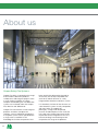
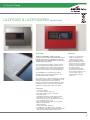
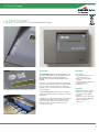
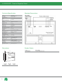
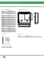
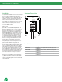
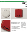
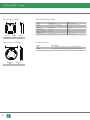
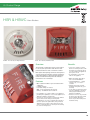
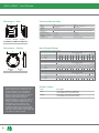
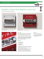
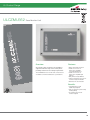
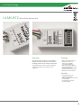
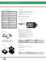
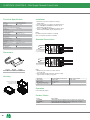
UL Listed Range
Fire Systems
ONE COOPER
Every day, thousands of people all over the world use products made by Cooper
Industries. As a premier global manufacturing company, we believe that great brands are
built on high quality and excellent service. Which is why our brands have earned leading
positions in the markets we serve. Cooper Safety specialises in products designed to save
lives and protect property in commercial, industrial and residential buildings. It’s just one
of the seven divisions that continue to uphold our reputation through unparalleled sales
support and customer service.
2
Contents
4
5
7
11
15
19
21
29
41
Introduction
Control Panels
Repeater Panels
Addressable Sensors
Conventional Detectors
Addressable Pull Stations
Horns/Strobes
Interfaces
Mini Modules
3
About us
Cooper Safety Fire Systems
Cooper Fire offers a comprehensive range
of UL listed fire detection products
suitable for a wide range of projects, from
a small simple installation to a large
complex multi building site. Fire detection
systems are marketed under the Cooper
Fire, Menvier and JSB brands.
Cooper Fire manufacturer a wide range of
products and offers complete fire
solutions, not just individual components.
A complete system can be specified from
a single source, confident in the
knowledge that all the components have
4
been specifically designed and tested to
ensure they are all fully compatible with
each other and will function as a truly
integrated fire detection and alarm system.
It is absolutely vital that all the elements of
a fire detection system are fully compatible
with each other. To support this
philosophy, a large multi-disciplined
research and development team is based
in the UK at the Cooper Doncaster facility,
responsible for the integration of the very
latest technology into the design of our
comprehensive range of fire products.
UL Product Range
ULDF6000 & ULDF6000RM Control Panels
Overview
Benefits
The Menvier ULDF6000 is a high specification
analogue, wall or rack mounted, UL Listed fire system
available in various loop configurations. It combines
sophisticated functionality with simple operation and
aesthetically pleasing design.
• Supports a comprehensive
range of soft addressing
modules and devices for
greater flexibility in design
• Menu driven graphical user
interface for ease of operation
• Reduced commissioning time
through soft addressing and
auto learn functions
• Programming and trouble
shooting time minimised by
using a range of features such
as auto config, walk test,
system details, analogue
values, etc
The control panel has the ability to support complex
cause and effect programming and a wide range of
user controllable functions make the system ideal for
a diverse range of projects from industrial applications
through to large multi site commercial developments.
The ULDF6000 uses soft addressing to minimise
installation time and remove the potential for error
associated with manual addressing.
Each of the system components have been specifically
designed to operate as part of a ULDF6000 UL Listed
system providing assurance that the panel, the
detectors, the interfaces and the ancillaries are all fully
compatible with each other and that the full range of
system functionality is supported by each device.
Features
• Touchscreen Display
• 2 or 4 Class A Style 7 SLC loops
• Event History Buffer (9,999 events) with
Date/Time stamp
• 4 Notification appliance circuits (NAC's) outputs.
• Dedicated alarm, trouble, AC trouble relays
• Short circuit isolators incorporated into each loop
• Up to 200 addresses per loop
• Fully monitored network cable up to 126 panels
• Optional integral printer
• Alarm Verification
• PAS (Positive Alarm Sequence)
• Pre-Signal per Point (NFPA 70, 72 compliant)
• Remote Alarm, NAC silenced, Alarm Reset, Trouble,
Supervisory and drill via addressable module
5
ULDF6000 & ULDF6000RM Control Panels
Technical Specification
Code
ULDF6000 and ULDF6000RM
Discription
UL Analgue Control Panel
Standards
UL864 9th edition
Primary Operating Supply
120/240 V, 60 Hz, 2.0 A Supervised
Secondary Operating Supply
Battery Voltage
Dimensions (Plastic)
Dimensions (Metal)
D2
D2
W
W
H
H
24 V dc
Battery Charge Current
1.0 A (max)
Battery Derating Factor
0.1
Battery Capacity Supervised
12 Ah (max)
Notification Appliance Circuits
Class B, Style Y, Sounder Group 1 sounder 1, Sounder Group 1 sounder 2,
Sounder Group 2 sounder 1, Sounder Group 2 sounder 2
Output Voltage
24 V dc
Output Current
0.75 (max)
Line Impedance
50 ohms
When the product is powered by 240 V ac, the
maximum current of 3.0 A is shared between
D1
H (mm)
398
W (mm)
505
D1
D1 (mm)
48
D2 (mm)
118
H (mm)
397
W (mm)
497
D1 (mm)
75
D2 (mm)
130
these circuits.
When the product is powered by 120 V ac, the
maximum current of 2.25 A is shared between
these circuits.
Supervised, Power limited, Regulated
Notification Appliance Circuits
Class B, Style Y, SYNC MODULE. NAC1, NAC2
Output Voltage
24 V dc
Output Current
0.5 A (max)
Line Impedance
50 ohms (max)
The maximum current of 0.5 A is shared
between these circuits.
Supervised, Power limited, Regulated
Alarm, Trouble Contacts. Relay Expansion
Unity Power Factor
30 V dc
For connection to power limited sources only
Aux Relay (AC Trouble) Contacts
Unity Power Factor
30 V dc, 1 A
For connection to power limited sources only
Signaling Line Circuit Style [7] Class [A] – (Addressable Loop)
Rated Voltage
24 V dc
Maximum Current
500 mA
Line Impedance
50 Ω (max)
Supervised, Power limited
Network SLC
Voltage
5 V dc
Current
100 mA (max)
Line Impedance
50Ω (max)
Power Limited
Limited to same-enclosure Installations
Compatibility
Suitable for use with
6
Menvier UL fire systems
Product Codes
Code
ULDF60002G
ULDF60004G
ULDF60002GP
ULDF60004GP
ULDF60002GNC
ULDF60004GNC
ULDF60002GPNC
ULDF60004GPNC
ULDF60002RM
ULDF60004RM
ULDF60002PRM
ULDF60004PRM
ULDF60002NCRM
ULDF60004NCRM
ULDF60002PNCRM
ULDF60004PNCRM
ULDFR6000L2
ULDFR6000L4
ULDFR6000L2NC
ULDFR6000L4NC
Description
2 Loop Panel
4 Loop Panel
2 Loop Panel c/w Integral Printer
4 Loop Panel c/w Integral Printer
2 Loop Panel c/w Network Card
4 Loop Panel c/w Network Card
2 Loop Panel c/w Integral Printer, Network Card
4 Loop Panel c/w Integral Printer, Network Card
2 Loop Panel Red Metal Box
4 Loop Panel Red Metal Box
2 Loop Panel c/w Integral Printer Red Metal Box
4 Loop Panel c/w Integral Printer Red Metal Box
2 Loop Panel c/w Network Card Red Metal Box
4 Loop Panel c/w Network Card Red Metal Box
2 Loop Panel c/w Integral Printer, Network Card Red Metal Box
4 Loop Panel c/w Integral Printer, Network Card Red Metal Box
Rack mounted 2 Loop Panel
Rack Mounted 4 Loop Panel
Rack Mounted 2 Loop Panel c/w Network Card
Rack Mounted 4 Loop Panel c/w Network Card
UL Product Range
ULDF6000PR Passive Repeater Panel
2 x 40 backlit LCD display and 6 supervisory LED’s
Overview
Features
The ULDF6000PR passive repeater panel, is a cost
effective system which can be programmed via its
informative display to be either fully passive
(display only) or semi passive (restricted system
control).
• Fully passive
• Up to 200 Repeaters can be
connected to the loop
• Surface or semi-recessed
mounting
• 2 x 40 backlit LCD display and
6 supervisory LED’s
• Compact size
When loop connected the repeater panel will display
the system information text of the connected control
panel and will provide a fire indication, with panel
number, of any connected network control panel that
has fire activation.
The ULDF6000PR repeater panel does not require
system programming, with the exception of local text
information.
In addition to this repeater panels main menu driven 2
x 40 backlit LCD display, which provides system
status information, it also has 6 supervisory LED’s
(Power On, Alarm, Trouble, Supervisory, Test In
Progress, and Scroll).
Benefits
• Menu driven easy to operate
• Simple connection to panel
SLC circuit reduces wiring
and time
• Distance run up to 2kms from
main panel without additional
cable and equipment,
saving cost
Simple user interface
7
ULDF6000PR - Passive Repeater Panel
Technical Specification
Code
ULDF6000PR
Description
Passive Repeater Panel
Standards
UL864 9th edition
Standard Connections
System Indicators
LED’s
Power on, Alarm, Trouble, Test, Supervisory,
Scroll LED’s
Mains Input, Supervised
Voltage
120 V ac to 240 V ac, 60 Hz
Current
35 mA
SLC Field Wiring
Current
0.354 mA
Wiring Gauge
12 (max) AWG
Wiring Class
Class A Style 7
Ground Fault
0.1 ohm
Supervisory, Power Limited
Yes
Line Impedance
50 Ω (max)
Batteries
Batteries
1x12 V dc, 3.2 Ah, 0.1 derating
Battery Charge Current
0.4 A
Standby Period
24 hours + 30min alarm
Download Comms
RS232 port
Environmental
Operating Temperature
0°C to 49°C
Humidity (Non Condensing)
0 to 93 %RH
Physical
Dimensions (H x W x D)
270mm x 332mm x 90mm
Weight
3.6kg (with batteries)
Ingress Protection
IP30
Construction
PC/ABS, UL94 5VA rating
Colour
Light Grey or Graphite
Cable Entry
12 x 20mm knockouts top of backbox
Compatibility
Suitable for use with
Menvier UL fire systems
Dimensions
Product Codes
Code
ULDF6000PR
D1
W
H
1
2
3
4
5
D2
H (mm)
395
8
W (mm)
332
D (mm)
115
Description
Passive Repeater Panel
UL Product Range
ULDPTR6000 Network Repeater Panel, Touch Screen
Overview
Benefits
The ULDPTR6000 repeater panel provides
sophisticated ‘touch screen’ functionality yet
achieves a simple end-user interface operation
within a compact panel design.
• Plug and play requires no
programming
• Easy to operate touch screen
display
• System integrity, fire alarm
system continues to operate
even if there is a short circuit or
open joint on cable
• Easy to change the language to
suit the operator
The ULDPTR6000 is designed to work with all UL
Listed Menvier analogue fire alarm control panels as
a network repeater. The Menvier ‘touch-screen’
repeater panel is easy to install and commission.
All text is transmitted via the network and is
automatically updated.
Features
• Plug and play. All information is downloaded
through the network
• Touch-screen display
• Integrated network capability allows networking
with the latest Menvier range of analogue fire alarm
control panels
• Multi language capability
• PSU approved to EN54 pt4 and UL864 9th Edition
• Up to 126 repeaters can be connected to
the network
• Programmable as an active or passive repeater
• Dual redundant network card to enhance
system integrity
9
ULDPTR6000 Repeater Panel, Touch Screen
Technical Specification
Code
ULDPTR6000
Description
Repeater Panel, Touch Screen
Standards
UL864 9 edition, NFPA 70-72
Mounting the Backbox
270.00
141.80
128.20
th
System Indicators
LED’s
Power on, Alarm, General Trouble, General
Supervisory, Power Trouble, System Trouble,
Test, NAC Trouble.
120 V ac to 240 V ac, 60 Hz
Current
100 mA
Network SLC
5 V dv, 11 mA (max)
Line impedance
50 ohm (max)
345.00
Voltage
229.80
Mains Input, Supervised, Power Limited
Batteries
Batteries
2x12 V dc, 7 Ah, 0.1 derating
Battery Charge Current
1.0 Amp
Standby Period
24 hours + 30min. alarm
Programable Relay
Programable Relay (Fire)
30 V, 1 A, Resistive
Download Comms
Download Comms
RS232 port
50.00
Environmental
Operating Temperature
0°C to 49°C
Humidity (Non Condensing)
0 to 93 %RH
Physical
Dimensions (H x W x D)
395mm x 332mm x 115mm
Weight
9kg (with batteries)
Ingress Protection
IP40
Construction
PC/ABS, UL94 5VA rating
325.00
4kg (without batteries)
Colour
Graphite
Display
Touch Screen
Cable Entry
11 x 20mm knockouts top of backbox
Compatibility
Suitable for use with
Menvier UL analogue addressable fire systems
Dimensions
Product Codes
Code
ULDPTR6000
D
H
W
H (mm)
395
10
W (mm)
332
D (mm)
115
Description
Repeater Panel, Touch Screen
UL Product Range
Addressable Sensors
Addressable Sensor, Optical (UCAP320)
Addressable Sensor, Opto-Heat (UCAPT340)
Addressable Sensor, Multi-Mode Heat (UCAH330)
Overview
Features
Photoelectric smoke sensor (opto) is suitable for
most applications giving the fastest response to slow
burning or smouldering fires which give rise to large
visible smoke particles.
• Built-in short circuit isolators
• Stylish low profile design
• 360º viewable LED design
• Removable detector chamber
• Drift compensation
Opto-heat sensor will respond better to fast clean
burning fires yet maintain the advantage of optical
sensors when detecting smouldering fires. The
thermal enhancement of this sensor allows a higher
alarm threshold which provides a greater rejection of
false alarms. The sensor will also give an alarm
at temperatures above 135°F.
Rate of rise with fixed heat sensor settings will detect
a rapid increase in temperature or temperatures
above 135°F and should be used in environments
where the ambient conditions might cause false
alarms if smoke detection were to be used, for
example where there is a high level of dust, fumes,
steam or smoke under normal conditions.
Benefits
• Plug and play no hard
addressing required
• ‘Clean me’ feature means
sensor can be cleaned on site
using the Menvier manual
cleaning procedure
• The programmable heat sensor
reduces the number of parts
required in the system
Fixed heat sensors settings will detect temperatures
above 135°F or 194°F and should be used in
environments where the ambient conditions might
cause false alarms if smoke detection were to be
used, for example where there is a high level of dust,
fumes, steam or smoke under normal conditions.
For photoelectric and opto-heat operation the sensor
automatically compensates for gradual increase in
the scatter signal due to contamination e.g. dust
build up.
11
Addressable Sensors
Technical Specification
Code
UCAP320
UCAPT340
Description
Addressable Sensor, Optical
Addressable Sensor, Opto-Heat
UCAH330
Addressable Sensor, Multi-Mode Heat
Standards
UL268
UL268
UL521
Supply Ratings
Working Voltage
18 V dc to 30 V dc
18 V dc to 30 V dc
18 V dc to 30 V dc
Voltage Waveform
Filtered dc +/- 1 V (max), ripple @120Hz
Filtered dc +/- 1 V (max), ripple @120Hz
Filtered dc +/- 1 V (max), ripple @120Hz
Standby Current
220 μA (average)
220 μA (average)
220 μA (average)
Alarm Current
5 mA (max)
5 mA (max)
5 mA (max)
Start-up Time
2 seconds
2 seconds
2 seconds
Reset Time
2 seconds (max)
2 seconds (max)
2 seconds (max)
Timings
Sensitivity
Sensitivity
2.55+/- 0.33%/ft
2.55+/- 0.33%/ft
N/A
Sensitivity Checker
Use No-Climb, TRUTEST, UL Listing 77TL
Use No-Climb, TRUTEST, UL Listing 77TL
Use No-Climb, TRUTEST, UL Listing 77TL
Heat Class
Heat Element Rating
N/A
135ºF
135ºF ROR + Fixed, + Fixed 135ºF Fixed, 194ºF Fixed
Heat Detector Spacing
N/A
50ft (heat alone operation)
50ft
Mounting Position
Ceiling in open areas
Ceiling in open areas
Ceiling in open areas
32ºF to 100ºF
32ºF to 100ºF
32ºF to 100ºF / 32ºF to 150ºF (194ºF setting)
Compatibility Indentifier
W002
W002
W002
Compatible Bases
WBA or UCAB300
WBA or UCAB300
WBA or UCAB300
Suitable for use with
Menvier UL fire systems
Menvier UL fire systems
Menvier UL fire systems
Environmental
Operating Temperature
Compatibility
Dimensions
Product Codes
Code
UCAP320
UCAPT340
UCAH330
Dia
D
Description
Optical
Opto-Heat
Multi-Mode Heat
12
Dia (mm)
101
101
101
D (excl base)
33
43
43
D (incl base)
45
55
55
Description
Addressable Sensor, Optical
Addressable Sensor, Opto Heat
Addressable Sensor, Multi-Mode Heat,
(Programmable as Rate of Rise 135°F or 194°F)
UL Product Range
UCAB300 Addressable Sensor Base
Addressable Sensor, Opto-Heat (UCAPT340)
Addressable Sensor, Optical (UCAP320)
Overview
Features
The UCAB300 has been specifically designed to be
compatible with UL range of analogue sensors.
• Additional space for termination
• Dedicated earth terminal
• Secure closure
This standard base is designed for flexibility,
simplicity and speed of installation.
Benefits
• Positive action ensures
detector is connected
• Quick and easy to terminate
wiring
Addressable Sensor, Multi-Mode Heat (UCAH330)
13
UCAB300 - Analogue Sensor Base
Installation
Utilising Locking Tab
Wiring Hints
Mounting base includes an optional feature to prevent
the removal of the detector without the use of a tool.
• Each terminal is suitable for clamping up to 2 wires.
• Clamping of 2 wires of very different diameters
under one screw is not commended.
• Suitable for mounting to mounting boxes with
50-80mm fixing centres.
1. Remove the standard fit retaining clip.
2. Insert the locking clip which is located at the centre
of the base as shown.
1
Mount the detector onto the base and rotate fully
clockwise until it finally clicks.
General
If difficulty is experienced when mounting the
detector, this may be due to the following:
• Wiring causing an obstruction - move or shorten
wires.
• Although the base is tolerant to uneven mounting
surfaces, a very uneven surface may cause the
base to deform when the mounting screws are
tightened down - loosen screws to reduce this
or slide base to a more flat position.
Dimensions
The detector is now locked into position. Remove by
utilising a suitable tool (eg a thin screwdriver) into the
hole in the detector cover. Gently push the tool into
the detector and rotate anticlockwise.
Warning!
Do not use high voltage testers when detectors
or control panel are connected to the system.
Product Codes
Code
UCAB300
D
Dia
Description
Sensor Base
14
Dia (mm) D (mm)
104
22
Description
Common Base
2
UL Product Range
Conventional Detectors
Conventional Detector, Optical (UCPD-2W)
Conventional Detector, Opto-Heat (UCPT-2W)
Conventional Detector, Multi-Mode Heat
(UCHT-2W, UCHTI-2W, UCHR-2W, UCHRI-2W)
Overview
Features
Photoelectric smoke detector (opto) is suitable for
most applications giving the fastest response to slow
burning or smouldering fires which give rise to large
visible smoke particles.
• Stylish low profile design
• 360º viewable LED design
• Removable detector chamber
• Drift compensation
Opto-heat detector will respond better to fast clean
burning fires yet maintain the advantage of optical
detectors when detecting smouldering fires. The
thermal enhancement of this detector allows a higher
alarm threshold which provides a greater rejection of
false alarms. The detector will also raise an alarm
at temperatures above 135°F.
Benefits
• Plug and play no hard
addressing required
• ‘Clean me’ feature means
sensor can be cleaned on
site using the Menvier manual
leaning procedure
Rate of Rise detector and Fixed Heat detector will
detect a rapid increase in temperature or
temperatures above 135°F or 194°F (dependent on
switch selection) and should be used in environments
where the ambient conditions might cause false
alarms if smoke detection were to be used, for
example where there is a high level of dust, fumes,
steam or smoke under normal conditions.
15
Conventional Detectors
Technical Specification
Code
UCPD-2W
UCPT-2W
UCHT-2W
UCHTI-2W
UCHR-2W
Description
Conventional Detector
Conventional Detector
Conventional Detector
Conventional Detector
Conventional Detector
Conventional Detector
Optical, 2 Wire
Opto-Heat, 2 Wire
Fixed Heat, 135ºF, 2 Wire
Fixed Heat, 194ºF, 2 Wire
Rate of Rise & Fixed Heat
Rate of Rise & Fixed Heat
135ºF, 2 Wire
194ºF, 2 Wire
UL268
UL268
UL521
UL251
UL251
UL251
Working Voltage
15 V dc to 30 V dc
15 V dc to 30 V dc
15 V dc to 30 V dc
15 V dc to 30 V dc
15 V dc to 30 V dc
15 V dc to 30 V dc
Voltage Waveform
Filtered dc +/- 1 V (max),
Filtered dc +/- 1 V (max),
Filtered dc +/- 1 V (max),
Filtered dc +/- 1 V (max),
Filtered dc +/- 1 V (max),
Filtered dc +/- 1 V (max),
ripple @120Hz
ripple @120Hz
ripple @120Hz
ripple @120Hz
ripple @120Hz
ripple @120Hz
Standby Current
95 μA (average)
95 μA (average)
70 μA (average)
70 μA (average)
70 μA (average)
70 μA (average)
must be held externally to
Standards
UCHRI-2W
Supply Ratings
Alarm Current
Surge Current
must be held externally to
must be held externally to
must be held externally to
must be held externally to
must be held externally to
40 mA (max)
40 mA (max)
40 mA (max)
40 mA (max)
40 mA (max)
40 mA (max)
340 μA (max)
340 μA (max)
340 μA (max)
340 μA (max)
340 μA (max)
340 μA (max)
Timings
Start-up Time
20 seconds
20 seconds
20 seconds
20 seconds
20 seconds
20 seconds
Reset Time
2 seconds (max)
2 seconds (max)
2 seconds (max)
2 seconds (max)
2 seconds (max)
2 seconds (max)
Sensitivity
2.55+/- 0.33%/ft
2.55+/- 0.33%/ft
N/A
N/A
N/A
N/A
Sensitivity Checker
Use No-Climb, TRUTEST,
Use No-Climb, TRUTEST,
Use No-Climb, TRUTEST,
Use No-Climb, TRUTEST,
Use No-Climb, TRUTEST,
Use No-Climb, TRUTEST,
UL Listing 77TL
UL Listing 77TL
UL Listing 77TL
UL Listing 77TL
UL Listing 77TL
UL Listing 77TL
Heat Element Rating
N/A
135ºF
135ºF
194ºF
135ºF
194ºF
Heat Detector Spacing
N/A
50ft (heat alone operation)
50ft
50ft
50ft
50ft
Mounting Position
Ceiling in open areas
Ceiling in open areas
Ceiling in open areas
Ceiling in open areas
Ceiling in open areas
Ceiling in open areas
Operating Temperature
32ºF to 100ºF
32ºF to 100ºF
32ºF to 100ºF
32ºF to 150ºF
32ºF to 150ºF
32ºF to 150ºF
Mounting Position
Ceiling in open areas
Ceiling in open areas
Ceiling in open areas
Ceiling in open areas
Ceiling in open areas
Ceiling in open areas
Compatibility Indentifier
W001
W001
W001
W001
W001
W001
Compatible Bases
CB or CB2E
CB or CB2E
CB or CB2E
CB or CB2E
CB or CB2E
CB or CB2E
Suitable for use with
Menvier UL fire systems
Menvier UL fire systems
Menvier UL fire systems
Menvier UL fire systems
Menvier UL fire systems
Menvier UL fire systems
Sensitivity
Heat Class
Environmental
Compatibility
Dimensions
Dia
D
Description
Optical
Opto-Heat
Multi-Mode Heat
Dia (mm)
101
101
101
D (excl base)
33
43
43
D (incl base)
45
55
55
Product Codes
Code
UCPTR-4W
UCPD-2W
UCPT-2W
UCHT-2W
UCHTI-2W
UCHR-2W
UCHRI-2W
16
Description
4 Wire Detector
2 Wire Detector, Optical
2 Wire Detector, Opto-Heat
2 Wire Detector, Fixed Heat 135°F
2 Wire Detector, Fixed Heat 194°F
2 Wire Detector. Rate of Rise and Fixed Heat 135°F
2 Wire Detector, Rate of Rise and Fixed Heat 194°F
UL Product Range
CB2E & CB Conventional Detector Bases
Conventional Detector, Optical (UCPD-2W)
CB - Wide Base
Conventional Detector, Opto-Heat (UCPT-2W)
Overview
Features
The CB2E and CB have been specifically designed
to be compatible with UL range of conventional
detectors.
• Additional space for termination
• Dedicated earth terminal
• Secure closure
Both bases have been designed for flexibility,
simplicity and speed of installation.
Benefits
• Positive action ensures
detector is securely connected
• Quick and easy to terminate
wiring
Conventional Detector, Multi-Mode Heat
(UCHT-2W, UCHTI-2W, UCHR-2W, UCHRI-2W)
17
CB2E & CB - Conventional Detector Bases
Installation
Utilising Locking Tab
Wiring Hints
Mounting base includes an optional feature to prevent
the removal of the detector without the use of a tool.
• Each terminal is suitable for clamping up to 2 wires.
• Clamping of 2 wires of very different diameters
under one screw is not commended.
• Suitable for mounting to mounting boxes with
50-80mm fixing centres.
1. Remove the standard fit retaining clip.
2. Insert the locking clip which is located at the centre
of the base as shown.
1
Mount the detector onto the base and rotate fully
clockwise until it finally clicks.
General
If difficulty is experienced when mounting the
detector, this may be due to the following:
• Wiring causing an obstruction - move or shorten
wires.
• Although the base is tolerant to uneven mounting
surfaces, a very uneven surface may cause the
base to deform when the mounting screws are
tightened down - loosen screws to reduce this
or slide base to a more flat position.
Dimensions
The detector is now locked into position. Remove by
utilising a suitable tool (eg a thin screwdriver) into the
hole in the detector cover. Gently push the tool into
the detector and rotate anticlockwise.
Warning!
Do not use high voltage testers when detectors or
control panel are connected to the system.
Product Codes
Code
CB2E
CB
D
Dia
Description
Detector Base
Wide Base
18
Dia (mm) D (mm)
102
22
158
22
Description
Detector Base
Wide Detector Base
2
UL Product Range
Addressable Pull Stations
UMPS-400X - Pull Station, Explosion Proof
UMPS-100 / UMPS-100WP / UMPS-200 - Pull Station
Overview
Features
This range of manual pull stations are constructed
of high quality, die-cast metal for long lasting
performance and may be mounted on a single gang
backbox.
• Mounting: Wall
• Single or dual action
• Terminal Strip Connections
• Key Reset
• Corrosion resistant
• Single gang back box
• Class A, style 7 SLC
Available in either single or dual action configurations
for indoor or outdoor use with SPST contacts and
terminal strip connections.
The addressable UMPS range consists of the UL
listed MPS range of pull stations and the UL listed
fast response addressable input initiating module
(ULMCIM-C).
Benefits
• High quality die cast metal case
for lasting performance
• Plug and play no hard
addressing required
All models are painted red with raised white lettering
and a locking mechanism to prevent unauthorized
reset.
19
Addressable Pull Stations
Installation
Standard Connection
The Series MPS Pull Station may be surface mounted
indoors with a separately ordered backbox option or
flush mounted on a standard single gang switch
plate. In either case be sure to follow local codes and
regulations. To comply with ADA standards the Pull
Station must be less than 48 inches above the floor
for front wheelchair access, and less than 54 inches
above the floor for side wheelchair access. MPS Pull
Stations, when mounted to the Series MPS-WP
Backbox with Gasket Assembly, are listed for outdoor
use and are NEMA-3R listed.
20
Loop In
Flush Mount
Most flush mount installations may be attached to a
standard single gang switch box (not supplied) The
only difference between a surface mount installation
and flush mount installation is that the two 6-32
screws are placed through the slots that are centered
on the metal plate.
Loop Out
Surface Mount
A surface mount installation uses a red diecast
(MPS-WB) or sheet metal (MPS-ISB) Backbox. The
backbox has four pre-drilled mounting holes of
0.187-inch diameter. A screw size of 8 or smaller can
be used to attach the backbox to a wall. After the
backbox is in place, attach the conduit. The diecast
backbox (MPS-WB) has an opening that is tapped for
a 1/2 inch NPT fitting which may be oriented at the
top or bottom when the box is attached to the wall.
The sheet metal backbox (MPS-ISB) has conduit
knockouts. Field wiring is connected to a terminal
block as shown in the wiring drawings. The wiring
should not be wrapped around the terminal, but
placed under the clamping plate. The housing is
locked using a keylock. Unlock the housing by
turning the key clockwise and swing down the front
of the housing to make the sheet metal mounting
plate accessible. Mount the metal plate to the
backbox using the four 1/4 inch length, 8-32 screws
that are supplied. If a Breakrod (MPS-RODS) is being
used, move the PULL handle to about a 45-degree
angle with the face of the housing. Insert a breakrod
into the cavity beneath the PULL handle. Place the
PULL handle back into the normal position (flush with
the housing). While holding the PULL handle in place,
move the housing back to the upright position and
lock. The Pull Station in now ready for operation.
Internal
Wiring
Addressable
Loop
Power
Limited
Product Codes
Code
UMPS-100
UMPS-400X
UMPS-100WP
UMPS-200
Description
Pull Station, SPST Single Action, Terminals, Key Reset
+ULMCIM-C
Pull Station, Explosion Proof, Single Action, Key Reset
+ULMCIM-C
Pull Station, SPST Single Action, Terminals, Key Reset
+ULMCIM-C
Pull Station, SPST Double Action, Terminals, Key Reset
+ULMCIM-C
UL Product Range
HNR & HNWC Horns
HNWC - Horn, Ceiling Mount
HNR - Horn, Wall Mount
Overview
Benefits
The UL range of notification devices are designed
to exceed your expectations and offer the most
polished, feature rich and cost effective solution.
• Up to 48% savings in current
draw over similar products,with
the latest horn/strobe products
you can install more appliances
per a given circuit.
Both stylish and inspiring, architects and engineers
can now specify the industry’s sleekest looking fire
notification appliance, while being afforded all the
features and benefits that provide the industry’s
lowest total cost of ownership.
Features
• A combination of 12 and 24 VDC in one appliance
providing the capability to use a single appliance for
different installation requirements
• A universal, common base for retrofit jobs, limited
space environments and pre-existing wire
configurations. It comes complete with a Contact
Cover for protection against dirt, dust, paint and
damage to the contacts. The Contact Cover also
acts as a shunting device to allow pre-wire testing
for common wiring issues.
• 80% reduction in SKUs - Up to 9 models now in 1
appliance (3 audible settings)
• Easier to install - Save up to
14% cost of installation
• 5 Mounting Options - 1 gang,
2 gang, 4”sq., 3.5 octal, 4”
octal box
• Voltage test points for quick
troubleshooting and easy spot
checking
• 1/16” deep mounting error relief
Pre-wire capability to check for
wiring & ground faults prior to
appliance installation
• Contact cover not only provides
protection from dirt, dust, paint
and accidental damage, it
allows for pre-wire testing and
troubleshooting
21
HNR & HNWC - Horns
Dimensions - Wall
Technical Specification
W
D
Code
HNR
HNWC
Description
Horn, Wall Mounted
Horn, Ceiling Mounted
Standards
UL Standard 1971 & UL Standard 464
UL Standard 1971 & UL Standard 464
90/95/99 dBA)
90/95/99 dBA)
Operation
12/24 V dc
H
Environmental
Operating Temperature
0°C to 49°C
0°C to 49°C
Humidity (Non Condensing)
0 to 93 %RH
0 to 93 %R
Menvier UL fire systems
Menvier UL fire systems
Compatibility
Suitable for use with
H (mm)
133
W (mm)
116
D (mm)
56
Dimensions - Ceiling
Dia
Dia (mm)
166
22
Product Codes
D
D (mm)
34
Code
HNR
HNWC
Description
Horn, Wall Mount, Snap Base, up to 105 dB @ 1meter
Horn, Ceiling Mount, Snap Base, up to 105 dB @ 1meter
UL Product Range
HSR & HSWC Horn Strobes
HSWC - Horn Strobe, Ceiling Mounted
HSR - Horn Strobe, Wall Mounted
Overview
Benefits
The UL range of notification devices are designed
to exceed your expectations and offer the most
polished, feature rich and cost effective solution.
• Up to 48% savings in current
draw over similar products, with
the latest horn/strobe products
you can install more appliances
per a given circuit.
• A combination of 12 and 24
VDC in one appliance
Both stylish and inspiring, architects and engineers
can now specify the industry’s sleekest looking fire
notification appliance, while being afforded all the
features and benefits that provide the industry’s
lowest total cost of ownership.
Features
• 80% reduction in SKUs - Up to 9 models now in
1 appliance
• 3 audible settings
• 8 candela settings in 1 device
Wall - 15/1575/30/75/95/110/135/185
Ceiling - 15/30/60/75/95/115/150/177
• A combination of 12 and 24 VDC in one appliance
providing the capability to use a single appliance for
different installation requirements
• A universal, common base for retrofit jobs, limited
space environments and pre-existing wire
configurations. It comes complete with a Contact
Cover for protection against dirt, dust, paint and
damage to the contacts. The Contact Cover also
acts as a shunting device to allow pre-wire testing
for common wiring issues.
• Easier to install - Save up to
14% cost of installation**
• 5 Mounting Options - 1 gang,
2 gang, 4”sq., 3.5 octal, 4”
octal box
• Voltage test points for quick
troubleshooting and easy spot
checking
• 1/16” deep mounting error relief
Pre-wire capability to check for
wiring & ground faults prior to
appliance installation
• Contact cover not only provides
protection from dirt, dust, paint
and accidental damage, it
allows for pre-wire testing and
troubleshooting
23
HSR & HSWC - Horn Strobes
Dimensions - Wall
Technical Specification
W
D
Code
HSR
HSWC
Description
Horn Strobes, Wall Mounted
Horn Strobes, Ceiling Mounted
Standards
UL Standard 464
UL Standard 464
15/1575/30/75/95/110/135/185 cd, 90/95/99 dB(A)
15/30/60/75/95/115/150/177 cd, 90/95/99 dB(A)
Opperation
12/24 Vdc
H
Environmental
Operating Temperature
0°C to 49°C
0°C to 49°C
Humidity (Non Condensing)
0 to 93 %RH
0 to 93 %RH
Menvier UL fire systems
Menvier UL fire systems
Compatibility
Suitable for use with
H (mm)
133
W (mm)
116
D (mm)
56
Horn Strobe Ratings
Dimensions - Ceiling
Dia
D
Horn Strobe Ratings per UL 1971 & UL 464 at 24 Vdc
UL Max Current* at 99 dB(A)
24 V dc
Mode
Regulated Voltage Range V dc
15
15/75
30
HS
8.0-33.0
0.082 0.095 0.102
HSC
8.0-33.0
0.082
60
75
95
110
115
0.148 0.176 0.197
0.102 0.141 0.148 0.176
12 V dc
135
150
177
0.242
0.197
185
15
15/75
0.282 0.125 0.159
0.242 0.282
0.125
Horn Strobe Ratings per UL 1971 & UL 464 at 24 V dc
UL Max Current* at 95 dB(A)
24 V dc
Dia (mm)
166
D (mm)
34
Mode
Regulated Voltage Range V dc
15
15/75
30
HS
8.0-33.0
0.073 0.083 0.087
HSC
8.0-33.0
0.073
60
75
95
110
115
0.139 0.163 0.186
0.087 0.128 0.139 0.163
12 V dc
135
150
177
0.230
0.186
185
15
15/75
0.272 0.122 0.153
0.230 0.272
0.122
Horn Strobe Ratings per UL 1971 & UL 464 at 24 V dc
UL Max Current* at 90 dB(A)
24 V dc
Mode
Regulated Voltage Range V dc
15
15/75
30
HS
8.0-33.0
0.065 0.075 0.084
HSC
8.0-33.0
0.065
60
75
95
110
115
0.136 0.157 0.184
0.084 0.120 0.136 0.157
12 Vdc
135
24
Code
HSR
HSWC
177
0.226
0.184
Product Codes
All strobe models are UL dual listed - meeting
both UL1638 and UL1971 requirements. As
dual listed appliances, these weatherproof
strobes are listed for outdoor applications
under UL 1638 as well as under UL 1971, the
Standard for Safety Signaling Devices for
Hearing Impaired. With an extended
temperature range of –31°F to 150°F (-40°C to
66°C), the weatherproof appliances meet or
exceed UL outdoor test requirements for rain,
humidity and corrosion resistance while
providing multiple strobe intensity options,
including the highest strobe ratings available
for area coverage per NFPA 72 strobe spacing
tables (up to 185 candela for wall mounting and
177 candela for ceiling mounting).
150
Description
Horn Strobe, Wall Mount, Snap Base,
153075100cd up to 105 dB @ 1meter
Horn Strobe, Ceiling Mount, Snap Base,
153075100cd up to 105 dB @ 1meter
185
15
15/75
0.267 0.120 0.148
0.226 0.267
0.120
UL Product Range
STR & STWC Synchronised Strobes
STWC - Synchronised Strobe, Ceiling Mounted
STR - Synchronised Strobe, Wall Mounted
Overview
Benefits
The UL range of notification devices are designed
to exceed your expectations and offer the most
polished, feature rich and cost effective solution.
• Up to 48% savings in current
draw over similar products, with
the latest horn/strobe products
you can install more appliances
per a given circuit.
Both stylish and inspiring, architects and engineers
can now specify the industry’s sleekest looking fire
notification appliance, while being afforded all the
features and benefits that provide the industry’s
lowest total cost of ownership.
Features
• Industry’s highest strobe candela options
• Models with field selectable tone, dBA and
candela settings
• Wall or ceiling mounting options
• Surface of semi-flush mounting
• IN/Out wiring termination accepting two #12-18
AWG wires at each terminal
• A combination of 12 and 24 VDC in one appliance
providing the capability to use a single appliance for
different installation requirements
• A universal, common base for retrofit jobs, limited
space environments and pre-existing wire
configurations. It comes complete with a Contact
Cover for protection against dirt, dust, paint and
damage to the contacts. The Contact Cover also
acts as a shunting device to allow pre-wire testing
for common wiring issues.
25
STR & STWC - Synchronised Strobes
Dimensions - Wall
Technical Specification
W
D
Code
STR
STWC
Description
Synchronised Strobes, Wall Mounted
Synchronised Strobes, Ceiling Mounted
Standards
UL Standard 1971
UL Standard 1971
15/1575/30/75/95/110/135/185 cd
15/1575/30/75/95/110/135/185 cd
Opperation
12/24 Vdc
H
Environmental
Operating Temperature
0°C to 49°C
0°C to 49°C
Humidity (Non Condensing)
0 to 93 %RH
0 to 93 %RH
Menvier UL fire systems
Menvier UL fire systems
Compatibility
Suitable for use with
H (mm)
133
W (mm)
116
D (mm)
56
Dimensions - Ceiling
Dia
Horn Strobe Ratings
D
Horn Strobe Ratings per UL 1971 & UL 464 at 24 Vdc
UL Max Current* at 99 dB(A)
24 V dc
Mode
Regulated Voltage Range V dc
15
15/75
30
HS
8.0-33.0
0.082 0.095 0.102
HSC
8.0-33.0
0.082
60
75
95
110
115
0.148 0.176 0.197
0.102 0.141 0.148 0.176
12 V dc
135
150
177
0.242
0.197
185
15
15/75
0.282 0.125 0.159
0.242 0.282
0.125
Horn Strobe Ratings per UL 1971 & UL 464 at 24 V dc
UL Max Current* at 95 dB(A)
24 V dc
Dia (mm)
166
D (mm)
34
Mode
Regulated Voltage Range V dc
15
15/75
30
HS
8.0-33.0
0.073 0.083 0.087
HSC
8.0-33.0
0.073
60
75
95
110
115
0.139 0.163 0.186
0.087 0.128 0.139 0.163
12 V dc
135
150
177
0.230
0.186
185
15
15/75
0.272 0.122 0.153
0.230 0.272
0.122
Horn Strobe Ratings per UL 1971 & UL 464 at 24 V dc
UL Max Current* at 90 dB(A)
24 V dc
All strobe models are UL dual listed - meeting
both UL1638 and UL1971 requirements. As
dual listed appliances, these weatherproof
strobes are listed for outdoor applications
under UL 1638 as well as under UL 1971, the
Standard for Safety Signaling Devices for
Hearing Impaired. With an extended
temperature range of –31°F to 150°F (-40°C to
66°C), the weatherproof appliances meet or
exceed UL outdoor test requirements for rain,
humidity and corrosion resistance while
providing multiple strobe intensity options,
including the highest strobe ratings available
for area coverage per NFPA 72 strobe spacing
tables (up to 185 candela for wall mounting and
177 candela for ceiling mounting).
26
Mode
Regulated Voltage Range V dc
15
15/75
30
HS
8.0-33.0
0.065 0.075 0.084
HSC
8.0-33.0
0.065
60
75
95
110
115
0.136 0.157 0.184
0.084 0.120 0.136 0.157
12 Vdc
135
150
177
0.226
0.184
185
15
15/75
0.267 0.120 0.148
0.226 0.267
0.120
Product Codes
Code
STR
STWC
Description
Synchronization Strobe, Wall Mount, Snap Base, 153075110cd
Synchronization Strobe, Ceiling Mount Snap Base, 15307595cd
UL Product Range
RSSWP-2475W-FR & RSSWP-2475C-FW
Synchronised Strobes, Outdoor
RSSWP-2475C-FW Synchronised Strobe, Ceiling Mounted, Outdoor
RSSWP-2475-FR Synchronised Strobe, Wall Mounted, Outdoor
Overview
Benefits
The UL range of notification devices are designed
to exceed your expectations and offer the most
polished, feature rich and cost effective solution.
• Up to 48% savings in current
draw over similar products, with
the latest horn/strobe products
you can install more appliances
per a given circuit.
Both stylish and inspiring, architects and engineers
can now specify the industry’s sleekest looking fire
notification appliance, while being afforded all the
features and benefits that provide the industry’s
lowest total cost of ownership.
Features
• Strobe Candela
• 77°F (25°C) 180cd
• -31°F (35°C) 75cd
• Voltage Range
• 12 VDC 8.0-17.5
• 24 VDC 16.0 - 33.0
• A combination of 12 and 24 VDC in one appliance
providing the capability to use a single appliance for
different installation requirements
• A universal, common base for retrofit jobs, limited
space environments and pre-existing wire
configurations. It comes complete with a Contact
Cover for protection against dirt, dust, paint and
damage to the contacts. The Contact Cover also
27
RSSWP-2475W-FR & RSSWP-2475C-FW - Synchronised Strobes, Outdoor
Dimensions
W
Technical Specification
D
Code
RSSWP-2475W-FR
RSSWP-2475C-FW
Description
Synchronised Strobes, Wall Mounted, Outdoor
Synchronised Strobes, Ceiling Mounted, Outdoor
Standards
UL1638 & UL1971
UL1638 & UL1971
Synchronisation strobe 75 cd
Synchronisation strobe 75 cd
Operation
H
Environmental
Operating Temperature
-40°C to 60°C
-40°C to 60°C
Humidity (Non Condensing)
0 to 95 %RH
0 to 95 %RH
Menvier UL fire systems
Menvier UL fire systems
Compatibility
Suitable for use with
H (mm)
131
W (mm)
131
D (mm)
110
All strobe models are UL dual listed - meeting
both UL1638 and UL1971 requirements. As
dual listed appliances, these weatherproof
strobes are listed for outdoor applications
under UL 1638 as well as under UL 1971, the
Standard for Safety Signaling Devices for
Hearing Impaired. With an extended
temperature range of –31°F to 150°F (-40°C to
66°C), the weatherproof appliances meet or
exceed UL outdoor test requirements for rain,
humidity and corrosion resistance while
providing multiple strobe intensity options,
including the highest strobe ratings available
for area coverage per NFPA 72 strobe spacing
tables (up to 185 candela for wall mounting and
177 candela for ceiling mounting).
28
Candela Ratings
Candela Ratings
Series
UL1971
UL1638 @ 77°F
UL1688 @ -40°F
Max Current
2475
30**
180
115
0.138
** Wall mount rating only
Product Codes
Code
RSSWP-2475W-FR
RSSWP-2475C-FW
WPSBB
WPSBB + WPKIT
WFP
Description
Synchronization Strobe, Wall Mount, Outdoor, 75cd
Synchronization Strobe, Ceiling Mount, Outdoor, 75cd
Exposed Conduit, Surface Mount
Concealed Conduit, Surface Mount
Back Box, Flush Mount
UL Product Range
ULCS354 4 Way Sounder Controller Unit
Overview
Features
An extensive range of interfaces are available to
support the Menvier range of UL control panels,
providing solutions for most design requirements.
• Quick and simple to install
• Avoids the need to wire
conventional sounders back
to the main panel
• 4 separate sounder circuits
(0.4 A)
• All outputs are independently
programmable
• Battery backup via integral
battery
• Built in short circuit isolator
class A style 7
The ULCS354 4 way sounder controller unit is a loop
connected interface, which provides the facility to
power and control 4 independent conventional
sounder circuits. This greatly simplifies installation in
applications where specialist sounders or beacons
are required by avoiding the need to connect them
directly to the analogue control panel.
The unit only uses a single address yet each circuit
can be independently controlled according to the
required cause and effect programming.
Benefits
• Plug and play, no hard
addressing required
• Increased system integrity. Self
powered independency of SLC
• No external short circuit isolator
required
• Beacon and strobe can be
wired direct to the interface
thereby saving time and cabling
29
ULCS354 - 4 Way Sounder Controller Unit
Technical Specification
Code
ULCS354
Description
4 Way Sounder Controller Unit
Standards
UL864 9th edition
Signalling Line Circuit
Installation
1. Remove the cover of the unit.
2. Fit the back-plate in position and pass the wires
into it taking care not to damage the circuit board.
3. Connect the unit according to the diagram below.
Style 7, Class A, Supervised, Power Limited
SLC Current
0.417 mA to 5.4 mA
Voltage
24 V
Line Impendance
50
Note:
No addressing of the interface is required. (See
control panel operation for details).
Sounder 1, 2, 3, 4
Style Y, Class B, Supervised, Power Limited
Voltage
24 V
Sounder Load Per Channel
0.4 A (max)
Sounder Load Total
1.6 A (max)
End of Line Resistor
6.8 k
Line Impedance
16 (max)
This unit requires a permanent 120/230 V ac supply.
Standard Connections
Mains Supply
6k8
Voltage
120 V ac to 240 V ac
Current
0.1 A
Frequency
60 Hz
6k8
6k8
6k8
ROUTE
AWAY
FROM EACH
OTHER
SUPER VISED POWER LIMITED
ROUTE
AWAY
FROM EACH
OTHER
Environmental
Operating Temperature
0°C to 49°C
Humidity (Non Condensing)
0 to 93 %RH
ADDRESSABLE
LOOP
230V AC MAINS
SUPER VISED
NON POWER LIMITED
Physical
Dimensions (H x W x D)
300mm x 300mm x 74mm
Weight
5.4kg
Ingress Protection
IP40
L
Battery Backup
2 x 12 V, 4 Ah, 0.1 derating factor
Standby
24 Hours + 30mins alarm
Charge Current
1 A (max)
N
E
230V AC
MAINS
+
-
1
+
-
2
-
+
+
3
-
4
-
+
+
BATT
-
2. The ANSI pattern is generated by the horns
themsleves.
H
Description
Wiring Gauge
Wiring Class
Ground Fault Impedance
Supervised, Power Limited
Line Impedance
Audible Synchronised
W
H (mm)
300
W (mm)
300
D (mm)
74
SLC Field Wiring Circuit (input)
12 Max AWG
Class A Style 7
0.1 ohm
Yes
50 ohms
N/A
Operation
Normal Standby, Alarm, Trouble.
Product Codes
Code
ULCS354
30
BACK UP
BATTER Y
-
Note:
1. The end of line resistors must always be fitted,
even if the sounder circuits are unused. Installer /
service engineer must ensure it is fitted.
D
+
IN
OUT
BATTER Y
NON SUPER VISED
NON POWER LIMITED
Menvier analogue addressable fire systems
Dimensions
+
SOUNDER CIRCUI T
Compatibility
Suitable for use with
-
Description
4 Way Sounder Controller Unit
Single Channel Input
12 Max AWG
Class B Style Y
0.1 ohm
Yes, Regulated
16 ohms
N/A
UL Product Range
ULCZMU352 Zone Monitor Unit
Overview
Features
An extensive range of interfaces are available to
support the Menvier range of UL control panels,
providing solutions for most design requirements.
• Quick and simple to install
• Monitors a zone of UL
approved compatible
conventional detectors
• Monitors a zone of UL
approved compatible pull
stations
• Only takes a single address
• Input monitored for open, short
circuits and ground trouble
• Built in short circuit isolator
The ULCZMU352 zone monitor unit connects zones
of suitable conventional detectors or pull stations.
Benefits
• Plug and play no hard
addressing required
• Easy to expand a system using
existing wiring
• No external short circuit
isolator required
31
ULCZMU352 - Zone Monitor Unit
Technical Specification
Code
ULCZMU352
Description
Zone Mointor Unit
Standards
UL864 9th edition
Signalling Line Circuit
Style 7, Class A, Supervised, Power Limited
Load Current
4.9 mA to 5.0 mA
Supply Voltage
24 V dc
Detector Zone
Style C, Class B, Supervised, Power Limited
Voltage
21 V dc to 26 Vdc, 22.9 V dc (nom)
Current (Alarm)
17 mA to 40 mA
Line Impendance
2.5 Ω (max)
End of Line Resistance
6.6 kΩ
Fire Input Trigger
680 Ω
Installation
1. Separate the two halves of the unit.
2. Drill out (or knock out) the required cable entries
in the surface mounting back-box.
3. Fit the back-box in position and pass the wires
into it.
4. Connect the unit according to the diagram below.
Note:
No addressing of the interface is required.
(See control panel operation for details).
Standard Connections
UPCD-2W, UCPT-2W, UCHRI, UCHT
5K1
680 Ohms
any combination thereof
Compatibility Identifier
6K8
ULCV1
Callpoint Zone
Style C, Class B, Supervised, Power Limited
- OUT+
Voltage
(8.4 Vpp pulsed every 1 second)
8.4 V
Current
1.2 mA
Trigger Resistor
680 Ω
End of Line Resistor
6.8 kΩ
Line Impedance
16 Ω
Maximum 20
Conventional
Detectors
- IN +
Addressable Loop
- OUT+
- IN +
Environmental
Operating Temperature
0°C to 49°C
Humidity (Non Condensing)
0 to 93 %RH
-
-
+
+
-
-
+
+
Physical
Dimensions (H x W x D)
180mm x 129mm x 60mm
Weight
0.28kg
Ingress Protection
IP65
OUT
LOOP
IN
Compatibility
Suitable for use with
DETECTOR
ZONE
Menvier analogue addressable fire systems
Note:
1. Maximum number of callpoints allowed is
unlimited.
2. Detector zone end of line device is 5k6 (supplied)
Dimensions
D
Note:
1. This unit can only be used with Menvier ULCB2E
or ULCB (CB) detector base and compatible
detectors.
2. The end of line resistor must always be fitted, even
if the spur is unused. Installer / service engineer
must ensure it is fitted.
3. Detector zone end of line device is 5k6 (supplied).
4. Compatibility Identifier ULCV1
5. Recommended cable type FPLP (plenum cable),
type FPLR (riser cable), or type FPL.
Description
Wiring Gauge
Wiring Class
Ground Fault Impedance
Supervised, Power Limited
H
W (mm)
129
SLC Field Wiring (input)
12 Max AWG
Class A Style 7
0.1 ohm
Yes
Operation
W
H (mm)
180
CALL
POINT
ZONE
D (mm)
60
Callpoint Zone:
Normal Standby, Alarm, NAC Silenced, Alarm Reset,
Trouble, Supervisory, Drill.
Detector Zone:
Normal Standby, Alarm, Trouble.
Product Codes
Code
ULCZMU352
32
Description
Zone Monitor Unit
Callpoint Zone
12 Max AWG
Class B Style C
0.1 ohm
Yes
Detector Zone
12 Max AWG
Class B Style C
0.1 ohm
Yes
UL Product Range
ULCSUM355 Shop Monitor Unit
Overview
Features
An extensive range of interfaces are available to
support the Menvier range of UL control panels,
providing solutions for most design requirements.
• Quick and simple to install
• Accepts a zone of UL approved
conventional detectors and
callpoints
• Provides 2 conventional
sounder circuits
• Only takes a single address
• Includes output changeover
relay
• Inputs monitored for open,
short circuits and ground
trouble
The ULCSUM355 shop monitor unit is designed to
enable small units with conventional fire detection to
be fully integrated with a main analogue addressable
fire system. It is ideal for applications such as
connecting individual shop units into a main
shopping centre system.
An external power supply is required to drive the 2
conventional sounder circuits. This power supply
must be UL1481 listed, regulated for fire and current
limited.
Benefits
• Plug and play no hard
addressing required
• Easy to expand a system using
existing wiring
• No external short circuit isolator
required
• Reduced installation cost by
using the 2 sounder circuits
33
ULCSUM355 - Shop Monitor Unit
Technical Specification
Code
ULCSUM355
Description
Shop Mointor Unit
Standards
UL864 9th edition
Signalling Line Circuit
Style 7, Class A, Supervised, Power Limited
Voltage
24 V dc
Current
4.9 mA to 5.0 mA
Line Impedance
50 Ω (max)
Style C, Class B, Supervised, Power Limited
Voltage
21 V dc to 26 V dc, 22.9 V dc (nom)
Current (Alarm)
17 mA to 40 mA
2.5 Ω (max)
End of Line Resistor
5.6 kΩ
Fire Input Trigger
680 Ω
1. Separate the two halves of the unit.
2. Drill out (or knock out) the required cable entries
in the surface mounting back-box.
3. Fit the back-box in position and pass the wires
into it.
4. Connect the unit according to the diagram below.
Note:
No addressing of the interface is required.
(See control panel operation for details).
Detector Zone
Line Impedance
Installation
Standard Connections
5K6
UL1481 LISTED FOR FIRE
24V DC OUTPUT
POWER SUPPL Y UNIT
Fault
Contact
N/O
UPCD-2W, UCPT-2W, UCHRI, UCHT
Compatibility Identifier
ULCV1
- IN
+
Addressable Loop
24 V dc
Current
1 A (max)
Line Impedance
8Ω
End of Line Resistance
12 kΩ
-
-
+
+
- OUT +
- IN
Callpoint Zone
-
12K
Style Y, Class B, Supervised, Power Limited
Voltage
24V
O/P
Maximum 20
Conventional
Detectors
- OUT +
Sounder 1, Sounder 2
12K
12K
6K8
any combination thereof
+
-
+
+
-
+
NC
-
+
-
+
-
+
Style C, Class B, Supervised, Power Limited
Voltage
OUT
(8.4 Vpp pulsed every 1 second)
8.4 V
Current
1.2 mA
Line Impedance
16 Ω
End of Line Resistor
6.8 kΩ
Trigger Resistor
680 Ω
DETECT OR
ZONE
FIRE
RELAY
24 V dc
Current
2 A (max)
End of Line Resistor
12 kΩ
Line Impendance
4Ω
Gauge Wire
12 AWG
Description
UL 1481 listed regulated for fire, current limited
Environmental
Operating Temperature
0°C to 49°C
Humidity (Non Condensing)
0 to 93 %RH
Physical
Dimensions (H x W x D)
180mm x 129mm x 60mm
Weight
0.28kg
Ingress Protection
IP65
Compatibility
Menvier analogue addressable fire systems
Wiring
Gauge
Wiring
Class
Ground
Fault
Impedance
Supervised,
Power
Limited
Callpoint
Zone
12
Max AWG
Class B
Style C
0.1 ohm
Detector
Zone
12
Max AWG
Class B
Style C
0.1 ohm
Yes
Yes
Yes
Operation
Callpoint Zone:
Normal Standby, Alarm, NAC Silenced, Alarm Reset,
Trouble, Supervisory, Drill.
Detector Zone:
Normal Standby, Alarm, Trouble.
H
W
34
2
EXTERNAL
PSU
MONITOR
24V
EXTERNAL
PSU
INPUT
Product Codes
D (mm)
60
Code
ULCSUM355
Sounder 1
Sounder 2
12
Max AWG
Class B
Style Y
0.1 ohm
24 V External
Supply
12
Max AWG
N/A
External
PSU Monitor
12
Max AWG
N/A
TBD
Power
Supply
Supervised
Power
Limited
TBD
Power
Supply
Supplementary
Regulated
Supervised
Power
Limited
ULCV1 Compatible Detectors: UPCD-2W, UCPT-2W, UCHRI, UCHT, UCHTI
D
W (mm)
129
-
+
1
SLC Field
Wiring (Input)
12
Max AWG
Class A
Style 7
0.1 ohm
Compatibility
Identifier
Dimensions
H (mm)
180
-
+
Note:
1. The end of line resistor must always be fitted, even
if the inputs are unused.
2. Recommended cable type FPLP (plenum cable),
type FPLR (riser cable), or type FPL.
Supervised, Power Limited
Suitable for use with
CALL
POINT
ZONE
SOUNDER
24 V external PSU
Voltage
IN
LOOP
Description
Shop Monitor Unit
UL Product Range
ULCSI350 Spur Isolator Unit
Overview
Features
An extensive range of interfaces are available to
support the Menvier range of UL control panels,
providing solutions for most design requirements.
• Quick and simple to install
• Allows a spur of analogue
devices to be fed from the
main loop
• Integral short circuit isolators
for the loop and the spur
• Automatically controls
addressing sequence
• Built in short circuit isolator
The ULCSI350 spur isolator unit enables a spur of
analogue devices to be connected to a main
analogue loop, the device is designed to simplify
installation of remote parts of buildings or for simple
system extensions.
Benefits
• Plug and play no hard
addressing required
• Easy to expand a system using
existing wiring
• Reduced installation cost
• No external short circuit
isolator required
35
ULCSI350 - Spur Isolator Unit
Technical Specification
Code
ULCSI350
Description
Spur Isolator Unit
Standards
UL864 9th edition
Signalling Line Circuit
Style 7, Class A, Supervised, Power Limited
Voltage
24 V dc
Current
0.30 mA to 0.33 mA
Spur Output
Installation
1. Fit the unit in position.
2. Connect the unit according to the diagram below.
Note:
A spur isolator unit must be used when making spurs
from the analogue addressable panel loop. Without
this unit, the self addressing features of the system
will not function correctly.
Style 4, Class B, Supervised, Power Limited
Voltage
24 V dc
Current
2 mA to 500 mA
Line Impedance
50 (max)
No addressing of the interface is required.
(See control panel operation for details).
Environmental
Operating Temperature
0°C to 49°C
Humidity (Non Condensing)
0 to 93 %RH
Standard Connections
Physical
Dimensions (W x H x D)
180mm x 129mm x 60mm
Weight
0.28kg
Ingress Protection
IP65
No End of
Line resistor
Required
Compatibility
Suitable for use with
Detectors
(see Notes)
Menvier analogue addressable fire systems
All connections are
Power Limited
Dimensions
Addressable Spur
- +
D
OUT
- +
H
IN
- +
To Loop Finish
From Loop Start
W
H (mm)
180
W (mm)
129
D (mm)
60
Note:
1. This unit can only be used with Menvier UCAB300
and WBA detector bases and
compatible detectors.
2. Recommended cable type FPLP (plenum cable),
type FPLR (riser cable), or type FPL.
Description
Wiring Gauge
Wiring Class
Ground Fault Impedance
Supervised, Power Limited
Max Line Impendance
SLC Field Wiring Circuit (input)
12 Max AWG
Class A Style 7
0.1 ohm
Yes
50
Product Codes
Code
ULCSI350
36
Description
Spur Isolator Unit
Single Channel Input
12 Max AWG
Class B Style 4
0.1 ohm
Yes
50
UL Product Range
ULCIO351 3 Channel I/O Unit
Overview
Features
An extensive range of interfaces are available to
support the Menvier range of UL control panels,
providing solutions for most design requirements.
• Quick and simple to install
• Soft addressed
• 3 separate inputs and 3
separate outputs
• Inputs monitored for open and
short circuits
• Integral short circuit isolator
The ULCIO351 three channel I/O unit enables simple
interfacing between the fire system and other
equipment such as nurse call systems or access
control systems. The inputs are fully monitored for
open, short circuits and ground trouble
Benefits
• Plug and play no hard
addressing required
• Built in short circuit isolator no
additional hardware required
• Unit takes 3 inputs, 3 outputs
- only 1 address required to
monitor and control saving on
equipment and installation
37
ULCI0351 - 3 Channel I/O Unit
Technical Specification
Code
ULCIO351
Description
3 Channel I/O Unit
Standards
UL864 9th edition
Signalling Line Circuit
Style 7, Class A, Supervised, Power Limited
Operating Voltage
24 V dc
Current
1.4 mA to 1.36 mA
Line Impedance
50 Ω
Installation
1. Separate the two halves of the unit.
2. Drill out (or knock out) the required cable entries
in the surface mounting back-box.
3. Fit the back-box in position and pass the wires
into it.
4. Connect the unit according to the diagram below.
Note:
No addressing of the interface is required.
(See control panel operation for details).
Inputs 1, 2, 3 Contact Only Initiating Circuit
Style C, Class B, Supervised, Power Limited
Voltage
(8.4 Vpp pulsed every 1 second)
8.4 (max)
Current
1 mA (max)
Line Impedance
16 Ω (max)
Trigger Resistance
5.6 kΩ
End of Line Resistor
22 kΩ
Standard Connections
Power Limited Circuits
Connect Only to a Power Limited Source
5k6
5k6
3 Contact Set Programmable
Voltage
5k6
Ouput 1, 2, 3
24 V dc to 30 V dc
Current
1 A (max, Resistive PF1)
Switching Power
33 kΩ (min)
Power Factor
1
22k
22k
22k
ADDRESSABLE LOOP
Environmental
Operating Temperature
0°C to 49°C
Humidity (Non Condensing)
0 to 93 %RH
Non Power Limited Circuits
-
Physical
Dimensions (H x W x D)
180mm x 129mm x 60mm
Weight
0.28kg
Ingress Protection
IP65
-
+
+
-
+
OUT
IN
LOOP
1
-
+
INPUTS
2
-
+
OUTPUTS
N/O C N/C N/O C N/C N/O C N/C
3
Compatibility
Relay1
Suitable for use with
Menvier analogue addressable fire systems
Dimensions
D
H
Relay2
Relay3
Note:
1. The end of line resistor must always be fitted, even
if the inputs are unused. Installer / service engineer
must ensure it is fitted.
2. Monitored inputs can detect open circuit, short
circuit or ground faults.
3. Output relays are volt-free contacts and are not
monitored, but most be conected to power
limited source.
4. Each I/O channel consumes a separate address
and has the facility for separate text for each
channel.
5. Recommended cable type FPLP (plenum cable),
type FPLR (riser cable), or type FPL.
W
H (mm)
180
W (mm)
129
D (mm)
60
Description
Wiring Gauge
Wiring Class
Ground Fault Impedance
Supervised, Power Limited
SLC Field Wiring (input)
12 Max AWG
Class A Style 7
0.1 ohm
Yes
Operation
Input 1, 2, 3 Operation:
Normal Standby (Default), Alarm, Alarm, NAC
Silenced, Alarm Reset, Trouble. Trouble, Supervisory,
Drill. (Features programmable using PC site installer).
Output 1, 2, 3 Operations:
Normal Standby, Alarm.
Product Codes
Code
ULCIO351
38
Description
3 Channel I/O Unit
Input 1, 2, 3
12 Max AWG
Class B Style C
0.1 ohm
Yes
Output 1, 2, 3
12 Max AWG
N/A
0.1 ohm
Programmable
UL Product Range
ULCMIO353 120 V / 230 V Relay Unit
Overview
Features
An extensive range of interfaces are available to
support the Menvier range of UL control panels,
providing solutions for most design requirements.
• Quick and simple to install
• Soft addressed
• Only takes a single address
• Integral short circuit isolator
The ULCMIO353 120 V / 230 V relay unit enables
simple interfacing between the fire system and other
equipment such as nurse call systems or access
control systems.
The ability of the output unit to switch mains also
makes the unit ideal for plant control or mains
powered door holders.
Benefits
• Plug and play no hard
addressing required
• Easy to expand a system using
existing wiring
• No external short circuit
isolator required
39
ULCMIO353 - 120 V / 230 V Relay Unit
Technical Specification
Code
ULCMIO353
Description
120 V / 230 V Relay Unit
Standards
UL864 9th edition
Signalling Line Circuit
Style 7, Class A, Supervised, Power Limited
Voltage
24 V dc
Current
335 µA to 395 µA
Line Impendance
50 ohm
Output 1 (Programmable)
Voltage
120 V ac to 230 V ac
Contact Rating
1 A Resistive
Power Factor
1
Environmental
Operating Temperature
0°C to 49°C
Humidity (Non Condensing)
0 to 93 %RH
Physical
Dimensions (W x H x D)
180mm x 129mm x 60mm
Weight
0.28kg
Ingress Protection
IP65
Installation
1. Separate the two halves of the unit.
2. Drill out (or knock out) the required cable entries
in the surface mounting back-box.
3. Fit the back-box in position and pass the wires
into it.
4. Connect the unit according to the diagram below.
5. The single channel I/O, ULCMIO353 is suitable for
one conduit connection. Only the mains is allowed
this conduit connection. The hub shall be
connected to the conduit before the hub is
connected to the enclosure.
Note:
No addressing of the interface is required.
(See control panel operation for details).
Standard Connections
Compatibility
Suitable for use with
Menvier analogue addressable fire systems
POWER
LIMITED
CIRCUITS
VOLT-FREE OUTPUT
230V RATED
NON
POWER
LIMITED
CIRCUITS
ANALOGUE ADDRESSABLE LOOP
Dimensions
D
-
+
IN
-
+
OUT
-
+
C
N/C N/O
NC
H
Note:
1. The end of line resistor must always be fitted, even
if the inputs are unused. Installer / service engineer
must ensure it is fitted.
W
H (mm)
180
W (mm)
129
D (mm)
60
Description
Wiring Gauge
Wiring Class
Ground Fault Impedance
Supervised, Power Limited
SLC Field Wiring (input)
12 Max AWG
Class A Style 7
0.1 ohm
Yes
Operation
Output 1 Operation:
Normal Standby, Alarm
Warning!
Segregate mains cable from other connections
to this unit.
120V / 230V relay output is un-fused. Ensure
that the 120V / 230V supply feeding this unit is
adequately protected.
Product Codes
Code
ULCMIO353
40
Description
120 V / 230 V Relay Unit
Output 2
12 Max AWG
N/A
0.1 ohm
Programmable
UL Product Range
ULMIU872 Micro Zone Monitor Unit
Overview
Features
An extensive range of interfaces are available to
support the Menvier range of UL control panels,
providing solutions for most design requirements.
• Quick and simple to install
• Monitors a zone of UL
approved compatible
conventional detectors
• Only takes a single address
• Input monitored for open and
short ground trouble
• Active end of line monitoring
• Built in short circuit isolator
The ULMIU872 zone monitor unit is an extremely
compact unit ideal for incorperation in other
equipment.
Benefits
• Plug and play no hard
addressing required
• Easy to expand a system using
existing wiring
• No external short circuit
isolator required
41
ULMIU872 - Micro Zone Monitor Unit
Technical Specification
Code
ULMIU872
Description
Zone Mointor Unit
Standards
UL864 9th edition
Installation
1. Fit the box in position using the mounting details below.
2. Connect the unit according to the diagram below.
3. The ULMIU872 module can be fitted inside a
junction box.
4. Up to 3 ULMIU872 modules can be fitted inside the
FIBOX as per diagram below.
Signalling Line Circuit
Style 7, Class A, Supervised, Power Limited
Voltage
24 V dc
Current
4.9 mA to 5.0 mA
Detector Zone
Style D, Class A, Supervised, Power Limited
Voltage
21 V dc to 26 V dc (22.9 nom)
Current
17 mA to 40 mA
Line Impedance
2.5 Ω (max)
End of Line Resistor
5.6 kΩ
Fire Input Trigger
680 kΩ
Note:
No addressing of the interface is required.
(See control panel operation for details).
Standard Connections
UPCD-2W, UCPT-2W, UCHRI, UCHT, UCHTI,
any combination thereof
5k6
Compatibility Identifier : ULCV1
0°C to 49°C
Humidity (Non Condensing)
0 to 93 %RH
Loop In
22k
Operating Temperature
5K6
Environmental
Maximum 20
Conventional
Detectors
Physical
Dimensions (H x W x D)
65mm x 35mm x 18.5mm
Weight
0.28kg
Ingress Protection
IP40
Loop Out
Addressable
Loop
Compatibility
Suitable for use with
Menvier analogue addressable fire systems
Dimensions
D
W
H (mm)
65
Note:
1. This unit can only be used with conventional
detector base and compatible detectors.
2. Only connect cable screen to its adjacent earth
terminal.
3. The end of line resistor must always be fitted, even
if the spur is unused. Installer / service engineer
must ensure it is fitted.
4. Maximum number of callpoints allowed is unlimited.
5. Detector zone end of line device is 5k6 (supplied).
6. Compatibility Identifier ULCV1.
7. Recommended cable type FPLP (plenum cable),
type FPLR (riser cable), or type FPL.
H
W (mm)
35
D (mm)
18.5
Description
Wiring Gauge
Wiring Class
Ground Fault Impedance
Supervised, Power Limited
SLC Field Wiring (input)
12 Max AWG
Class A Style 7
0.1 ohm
Yes
Detector Zone
12 Max AWG
Class B Style C
0.1 ohm
Yes
Operation
Housing
FR4 PCB Interface Plate
Secured to box with
2 self tapping screws.
Normal Standby, Alarm, Alarm Test, Alarm Silence,
Alarm Reset, Trouble. Trouble Silence, Off- normal
position of switches
Product Codes
60mm
180mm
130mm
42
Code
ULMIU872
ULBU
Description
Micro Zone Monitor Unit
Mini Module Box Unit (Empty box)
UL Product Range
ULMCOM & ULMCOM-S Mini Single Channel Output Units
ULMCOM-S - Identified by panel as sounder
UL approved micro interface
Overview
Features
An extensive range of interfaces are available to
support the Menvier range of UL control panels,
providing solutions for most design requirements.
• Quick and simple to install
• Compact size
• Soft Addressed
• Integral short circuit isolator
The ULMCOM and ULMCOM-S are single channel
output units and are extremely compact and
therefore ideal for incorporation into other equipment.
Benefits
The ULMCOM is identified by the panel as an
input/output unit.
• Plug and play no hard
addressing required
• No external short circuit
isolator required
The ULMCOM-S is identified by the panel as a
sounder.
The maximum number of ULMCOM-S units per loop
is 60, and is counted towards the total number of
sounders on the loop.
43
ULMCOM & ULMCOM-S - Mini Single Channel Output Units
Technical Specification
Installation
Code
ULMCOM and ULMCOM-S
Description
Single Channel Output Units
Standards
UL864 9th edition
Signalling Line Circuit
Style 7, Class A, Supervised, Power Limited
Current
0.322 mA (max)
Output Relay
1. Fit the box in position using the mounting
details below.
2. Connect the unit according to the diagram below.
3. The ULMCOM & ULMCOM-S modules can be
fitted inside a junction box.
4. Up to 3 ULMCOM & ULMCOM-S modules can be
fitted inside the FIBOX, as per diagram below.
Supervisory Programmable
Switching Voltage
24 V dc to 30 V dc
Contact Rating
1 A Resistive, pf=1 (max)
Max Line Impedance
16 Ω
Power Factor
1
Note:
No addressing of the interface is required.
(See control panel operation for details).
Environmental
Operating Temperature
0°C to 49°C
Humidity (Non Condensing)
0 to 93 %RH
Standard Connections
Physical
Dimensions (H x W x D)
65mm x 35mm x 18.5mm
Weight
>0.1kg
Ingress Protection
IP40
Compatibility
Loop In
Suitable for use with
Menvier analogue addressable fire systems
Loop Out
Relay Contacts Must
Be Connected to a
Power Limited Source
Dimensions
Addressable
Loop
D
W
H (mm)
65
H
W (mm)
35
D (mm)
18.5
Loop In
Loop Out
Relay Contacts Must
Be Connected to a
Power Limited Source
Addressable
Loop
Note:
1. Output relay are volt-free contacts and are
not monitored.
2. Recommended cable type FPLP (plenum cable),
type FPLR (riser cable), or type FPL.
Housing
FR4 PCB Interface Plate
Secured to box with
2 self tapping screws.
Description
Wiring Gauge
Wiring Class
Ground Fault Impedance
Supervised, Power Limited
SLC Field Wiring Circuit (input)
12 Max AWG
Class A Style 7
0.1 ohm
Yes
Single Channel Output
12 Max AWG
Yes
Operation
60mm
Normal Standby, Alarm.
180mm
130mm
Product Codes
Code
ULMCOM
ULMCOM-S
ULBU
44
Description
Mini Single Channel Output Unit (recognised as output unit)
Mini Single Channel Output Unit (recognised as sounder)
Mini Module Box Unit (Empty box)
UL Product Range
ULMCIM & ULMCIM-C Mini Single Channel Input Units
ULMCIM-C - Identified by panel as callpoint
UL approved mico interface
Overview
Features
An extensive range of interfaces are available to
support the Menvier range of UL control panels,
providing solutions for most design requirements.
• Quick and simple to install
• Compact size
• Soft Addressed
• Integral short circuit isolator
The ULMCIM and ULMCIM-C are designed for use
with water flow switches and other applications
requiring the monitoring of dry contact alarm devices.
Benefits
The ULMCIM and ULMCIM-C are single channel
input units and are extremely compact and therefore
ideal for incorporation into other equipment.
• Plug and play no hard
addressing required
• No external short circuit
isolator required
The ULMCIM-C is designed for use with pull stations
(fast response to alarm)
The ULMCIM-C is identified by the panel as a
callpoint.
45
ULMCIM & ULMCIM-C - Mini Single Channel Input Units
Technical Specification
Installation
Code
ULMCIM and ULMCIM-C
Description
Single Channel Input Units
Standards
UL864 9th edition
Signalling Line Circuit
Style 7, Class A, Supervised, Power Limited
Current
332 µA
Operating Voltage
24 V dc
1. Fit the box in position using the mounting details
below.
2. Connect the unit according to the diagram below.
3. ULMCIM & ULMCIM-S module can be fitted inside
a junction box.
4. Up to 3 ULMCIM & ULMCIM-C modules can be
fitted inside the FIBOX, as per diagram below.
Input
Initiating Circuit Class B, Style C, Supervised, Power Limited
Voltage (8.4 Vpp every 1 second)
8.4 V dc
Current
1.2 mA
Trigger Resistance
5.6 k
End Of Line Resistor
22 k
Line Impendance
16 (max)
Note:
No addressing of the interface is required.
(See control panel operation for details).
This needs to be programmed as a callpoint on site
installed PC software.
Environmental
Operating Temperature
0°C to 49°C
Humidity (Non Condensing)
0 to 93 %RH
Standard Connections
Physical
Dimensions (H x W x D)
65mm x 35mm x 18.5mm
Weight
>0.1kg
Ingress Protection
IP40
5K6
Suitable for use with
22K
Compatibility
Menvier analogue addressable fire systems
Loop In
Loop Out
Addressable
Loop
Dimensions
5K6
22K
D
W
H (mm)
65
Loop In
Loop Out
H
W (mm)
35
Housing
FR4 PCB Interface Plate
Secured to box with
2 self tapping screws.
D (mm)
18.5
Addressable
Loop
Note:
1. The end of line resistor provided must always
be fitted, even if the input is unused.
2. Monitored inputs can detect open or short
circuit faults.
3. Recommended loop cable type: FIRETUF,
FP200, MICC.
Description
Wiring Gauge
Wiring Class
Ground Fault Impedance
Supervised, Power Limited
SLC Field Wiring Circuit (input)
12 Max AWG
Class A Style 7
0.1 ohm
Yes
Single Channel Input
12 Max AWG
Class B Style C
0.1 ohm
Yes
Operation
60mm
Normal Standby, Alarm, NAC Silenced, Alarm Reset, Trouble, Supervisory, Drill
180mm
130mm
Product Codes
Code
ULMCIM
ULMCIM-C
ULBU
46
Description
Mini Single Channel Input Unit (recognised as input unit)
Mini Single Channel Input Unit (recognised as callpoint)
Mini Module Box Unit (Empty box)
UL Product Range
Conditions of sale
All goods supplied are subject to the company’s general
conditions of sale which are available on request.
Trade Descriptions
All descriptions represent only particulars of the goods
to which they apply and do not form part of any contract.
The company reserves the right to change specification
without prior notification or public announcement.
®2010 Menvier
All rights reserved.
47
Abu Dhabi
Cooper Middle East
P.O. Box 53234, Karama
Villa 4 opp. Govt. Dept. Sports
Association, Sector 2-17
Street 6 (off Delma St No. 13)
Abu Dhabi UAE
T: +971 2 446 6840
F: +971 2 446 6841
Dubai
Cooper Middle East
PO Box 30861
Suite 302, Building 49
Dubai Healthcare City
Dubai
United Arab Emirates
T: +971 4427 2500
F: +971 4429 8521
Egypt
1169, Ministries Square
Sheraton Helipolis Area
Building 1, Cairo
Egypt
T: +202 2269 1134
F: +202 2269 1135
United Kingdom
Cooper Safety Fire Systems
Cooper Lighting and Safety Ltd
Wheatley Hall Road
Doncaster
South Yorkshire
DN2 4NB
United Kingdom
Qatar
Office No. 237, 2nd Floor Building
No. 81, 'D' Ring Road
Old Airport Area
P.O. Box 55582
Doha
Qatar
T: +974 5515 9948
Saudi Arabia
Cooper Middle East
P.O. Box 6315
3rd Floor Kaki Centre, Office 203
Tahlia Street (opposite IKEA)
21442 Jeddah
KSA
T: +966 2668 7703
F: +966 2663 6552
Australia
Cooper Industries Australia
P.O. Box 2577
205 – 209 Woodpark Road
Smithfield, N.S.W. 2164
Australia
T: +02 8787 2777
F: +02 9609 2342
Sales
T: +44 (0)1302 303 999
F: +44 (0)1302 303 333
E: [email protected]
China
Cooper Safety China
Cooper Electric (Shanghai) Co, Ltd.
3F, 9th Building, No. 6101
Longdong Avenue
East Area of Zhangjiang
High Tech Park, Pudong
Shanghai
China 201201
T: + 86 21 6891 9988
India
Cooper Safety
Cooper India Pvt. Ltd.
DLF Cyber City
Building 10A, Ground Floor
Sector 25, Gurgaon – 122002
India
T: +91 124 468 3888
Vietnam
Cooper Industries Vietnam
F4.1, 39 Nguyen
Thi Dieu St, ward 6
Dist. 03, Ho Chi Minh City
Vietnam
T: +848 6290 9639
F: +848 6290 6549
Export
T: +44 (0)1302 303 344
F: +44 (0)1302 303 345
E: [email protected]
www.cooperfire.com
Ref: UL/M/E/01/11
The trade names and brand names contained herein are valuble trademarks of Cooper Industries in the U.S. and other countries. You are not permitted to use the Cooper
Trademarks without the prior written consent of Cooper Industries.
Cooper Industries plc
600 Travis, Suite 5600
Houston, TX 77002 - 1001
T: 713 - 209 - 8400
www.cooperindustries.com