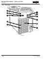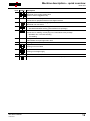
1
Operating instructions Welding machine Taurus 355 Synergic S TDM Taurus 405 Synergic S TDM Taurus 505 Synergic S TDM Observe additional system documents! Register now! For your benefit Jetzt Registrieren und Profitieren! www.ewm-group.com 10.06.2013 * *Details for ewm-warranty www.ewm-group.com 099-005219-EW501 General instructions CAUTION Read the operating instructions! The operating instructions provide an introduction to the safe use of the products. • Read the operating instructions for all system components! • Observe accident prevention regulations! • Observe all local regulations! • Confirm with a signature where appropriate. NOTE In the event of queries on installation, commissioning, operation or special conditions at the installation site, or on usage, please contact your sales partner or our customer service department on +49 2680 181-0. A list of authorised sales partners can be found at www.ewm-group.com. Liability relating to the operation of this equipment is restricted solely to the function of the equipment. No other form of liability, regardless of type, shall be accepted. This exclusion of liability shall be deemed accepted by the user on commissioning the equipment. The manufacturer is unable to monitor whether or not these instructions or the conditions and methods are observed during installation, operation, usage and maintenance of the equipment. An incorrectly performed installation can result in material damage and injure persons as a result. For this reason, we do not accept any responsibility or liability for losses, damages or costs arising from incorrect installation, improper operation or incorrect usage and maintenance or any actions connected to this in any way. © EWM HIGHTEC WELDING GmbH · Dr. Günter-Henle-Str. 8 · D-56271 Mündersbach, Germany The copyright to this document remains the property of the manufacturer. Reprinting, including extracts, only permitted with written approval. Subject to technical amendments. Contents Notes on the use of these operating instructions 1 Contents 1 Contents .................................................................................................................................................. 3 2 Safety instructions ................................................................................................................................. 5 2.1 Notes on the use of these operating instructions .......................................................................... 5 2.2 Explanation of icons ....................................................................................................................... 6 2.3 General .......................................................................................................................................... 7 2.4 Transport and installation ............................................................................................................ 11 2.4.1 Ambient conditions ....................................................................................................... 12 2.4.1.1 In operation ................................................................................................... 12 2.4.1.2 Transport and storage ................................................................................... 12 3 Intended use ......................................................................................................................................... 13 3.1 Use and operation solely with the following machines ................................................................ 13 3.2 Applications.................................................................................................................................. 14 3.2.1 MIG/MAG standard welding ......................................................................................... 14 3.2.1.1 forceArc ......................................................................................................... 14 3.2.1.2 rootArc ........................................................................................................... 14 3.2.2 TIG (Liftarc) welding ..................................................................................................... 14 3.2.3 MMA welding ................................................................................................................ 14 3.2.3.1 Air arc gouging .............................................................................................. 14 3.3 Documents which also apply ....................................................................................................... 15 3.3.1 Warranty ....................................................................................................................... 15 3.3.2 Declaration of Conformity ............................................................................................. 15 3.3.3 Welding in environments with increased electrical hazards ......................................... 15 3.3.4 Service documents (spare parts and circuit diagrams) ................................................ 15 3.3.5 Calibration/Validation ................................................................................................... 15 4 Machine description – quick overview .............................................................................................. 16 4.1 Front view .................................................................................................................................... 16 4.2 Rear view ..................................................................................................................................... 18 5 Design and function............................................................................................................................. 20 5.1 General ........................................................................................................................................ 20 5.2 Machine cooling ........................................................................................................................... 21 5.3 Workpiece lead, general .............................................................................................................. 21 5.4 Installation .................................................................................................................................... 22 5.5 Notes on the installation of welding current leads ....................................................................... 23 5.6 Welding torch cooling system ...................................................................................................... 24 5.6.1 Cooling module connection .......................................................................................... 24 5.7 Mains connection ......................................................................................................................... 25 5.7.1 Mains configuration ...................................................................................................... 25 5.8 Connecting the intermediate hose package to the power source ............................................... 26 5.8.1 Intermediate hose package strain relief ....................................................................... 26 5.8.2 Intermediate hose package connection ....................................................................... 27 5.9 Shielding gas supply (shielding gas cylinder for welding machine)............................................. 28 5.10 Welding torch holder .................................................................................................................... 29 5.11 MIG/MAG welding ........................................................................................................................ 30 5.11.1 Connection for workpiece lead ..................................................................................... 30 5.12 TIG welding .................................................................................................................................. 31 5.12.1 Welding torch connection ............................................................................................. 31 5.12.2 Connection for workpiece lead ..................................................................................... 31 5.13 MMA welding ............................................................................................................................... 32 5.13.1 Connecting the electrode holder and workpiece lead .................................................. 32 5.14 Remote control............................................................................................................................. 33 5.15 Interfaces ..................................................................................................................................... 34 5.15.1 PC Interfaces ................................................................................................................ 34 099-005219-EW501 10.06.2013 3 Contents Notes on the use of these operating instructions 6 Maintenance, care and disposal ......................................................................................................... 35 6.1 General......................................................................................................................................... 35 6.2 Maintenance work, intervals ........................................................................................................ 35 6.2.1 Daily maintenance tasks ............................................................................................... 35 6.2.1.1 Visual inspection ........................................................................................... 35 6.2.1.2 Functional test ............................................................................................... 35 6.2.2 Monthly maintenance tasks .......................................................................................... 36 6.2.2.1 Visual inspection ........................................................................................... 36 6.2.2.2 Functional test ............................................................................................... 36 6.2.3 Annual test (inspection and testing during operation) .................................................. 36 6.3 Maintenance work ........................................................................................................................ 36 6.4 Disposing of equipment................................................................................................................ 37 6.4.1 Manufacturer's declaration to the end user .................................................................. 37 6.5 Meeting the requirements of RoHS.............................................................................................. 37 7 Rectifying faults.................................................................................................................................... 38 7.1 Checklist for rectifying faults ........................................................................................................ 38 7.2 Error messages (power source) ................................................................................................... 39 7.3 Resetting JOBs (welding tasks) to the factory settings ................................................................ 41 7.3.1 Resetting a single JOB ................................................................................................. 41 7.3.2 Resetting all JOBs ........................................................................................................ 42 7.4 Vent coolant circuit ....................................................................................................................... 43 8 Technical data....................................................................................................................................... 44 8.1 Taurus 355 TDM .......................................................................................................................... 44 8.2 Taurus 405 TDM .......................................................................................................................... 45 8.3 Taurus 505 TDM .......................................................................................................................... 46 9 Accessories .......................................................................................................................................... 47 9.1 System components..................................................................................................................... 47 9.2 Options ......................................................................................................................................... 47 9.3 Welding torch cooling system ...................................................................................................... 47 9.4 Transport systems........................................................................................................................ 47 9.5 Remote control / connection cable............................................................................................... 47 9.6 General accessories .................................................................................................................... 48 9.7 Computer communication ............................................................................................................ 48 10 Appendix A............................................................................................................................................ 49 10.1 JOB-List........................................................................................................................................ 49 11 Appendix B............................................................................................................................................ 50 11.1 Overview of EWM branches......................................................................................................... 50 4 099-005219-EW501 10.06.2013 Safety instructions Notes on the use of these operating instructions 2 Safety instructions 2.1 Notes on the use of these operating instructions DANGER Working or operating procedures which must be closely observed to prevent imminent serious and even fatal injuries. • Safety notes include the "DANGER" keyword in the heading with a general warning symbol. • The hazard is also highlighted using a symbol on the edge of the page. WARNING Working or operating procedures which must be closely observed to prevent serious and even fatal injuries. • Safety notes include the "WARNING" keyword in the heading with a general warning symbol. • The hazard is also highlighted using a symbol in the page margin. CAUTION Working or operating procedures which must be closely observed to prevent possible minor personal injury. • The safety information includes the "CAUTION" keyword in its heading with a general warning symbol. • The risk is explained using a symbol on the edge of the page. CAUTION Working and operating procedures which must be followed precisely to avoid damaging or destroying the product. • The safety information includes the "CAUTION" keyword in its heading without a general warning symbol. • The hazard is explained using a symbol at the edge of the page. NOTE Special technical points which users must observe. • Notes include the "NOTE" keyword in the heading without a general warning symbol. Instructions and lists detailing step-by-step actions for given situations can be recognised via bullet points, e.g.: • Insert the welding current lead socket into the relevant socket and lock. 099-005219-EW501 10.06.2013 5 Safety instructions Explanation of icons 2.2 Explanation of icons Symbol Description Press Do not press Turn Switch Switch off machine Switch on machine ENTER ENTER NAVIGATION EXIT 4s ENTER (enter the menu) NAVIGATION (Navigating in the menu) EXIT (Exit the menu) Time display (example: wait 4s/press) Interruption in the menu display (other setting options possible) Tool not required/do not use Tool required/use 6 099-005219-EW501 10.06.2013 Safety instructions General 2.3 General DANGER Electromagnetic fields! The power source may cause electrical or electromagnetic fields to be produced which could affect the correct functioning of electronic equipment such as IT or CNC devices, telecommunication lines, power cables, signal lines and pacemakers. • Observe the maintenance instructions! (see Maintenance and Testing chapter) • Unwind welding leads completely! • Shield devices or equipment sensitive to radiation accordingly! • The correct functioning of pacemakers may be affected (obtain advice from a doctor if necessary). Do not carry out any unauthorised repairs or modifications! To avoid injury and equipment damage, the unit must only be repaired or modified by specialist, skilled persons! The warranty becomes null and void in the event of unauthorised interference. • Appoint only skilled persons for repair work (trained service personnel)! Electric shock! Welding machines use high voltages which can result in potentially fatal electric shocks and burns on contact. Even low voltages can cause you to get a shock and lead to accidents. • Do not touch any live parts in or on the machine! • Connection cables and leads must be free of faults! • Switching off alone is not sufficient! • Place welding torch and stick electrode holder on an insulated surface! • The unit should only be opened by specialist staff after the mains plug has been unplugged! • Only wear dry protective clothing! • Wait for 4 minutes until the capacitors have discharged! WARNING Risk of injury due to radiation or heat! Arc radiation results in injury to skin and eyes. Contact with hot workpieces and sparks results in burns. • Use welding shield or welding helmet with the appropriate safety level (depending on the application)! • Wear dry protective clothing (e.g. welding shield, gloves, etc.) according to the relevant regulations in the country in question! • Protect persons not involved in the work against arc beams and the risk of glare using safety curtains! Explosion risk! Apparently harmless substances in closed containers may generate excessive pressure when heated. • Move containers with inflammable or explosive liquids away from the working area! • Never heat explosive liquids, dusts or gases by welding or cutting! 099-005219-EW501 10.06.2013 7 Safety instructions General WARNING Smoke and gases! Smoke and gases can lead to breathing difficulties and poisoning. In addition, solvent vapour (chlorinated hydrocarbon) may be converted into poisonous phosgene due to the ultraviolet radiation of the arc! • Ensure that there is sufficient fresh air! • Keep solvent vapour away from the arc beam field! • Wear suitable breathing apparatus if appropriate! Fire hazard! Flames may arise as a result of the high temperatures, stray sparks, glowing-hot parts and hot slag produced during the welding process. Stray welding currents can also result in flames forming! • Check for fire hazards in the working area! • Do not carry any easily flammable objects such as matches or lighters. • Keep appropriate fire extinguishing equipment to hand in the working area! • Thoroughly remove any residue of flammable substances from the workpiece before starting welding. • Only continue work on welded workpieces once they have cooled down. Do not allow to come into contact with flammable material! • Connect welding leads correctly! Risk of accidents if these safety instructions are not observed! Non-observance of these safety instructions is potentially fatal! • Carefully read the safety information in this manual! • Observe the accident prevention regulations in your country. • Inform persons in the working area that they must observe the regulations! Danger when coupling multiple power sources! Coupling multiple power sources in parallel or in series has to be carried out by qualified personnel and in accordance with the manufacturer's guidelines. Before bringing the power sources into service for arc welding operations, a test has to verify that they cannot exceed the maximum allowed open circuit voltage. • Connection of the machine may be carried out by qualified personnel only! • When decommissioning individual power sources, all mains and welding current leads have to be safely disconnected from the welding system as a whole. (danger due to inverse voltages)! CAUTION Noise exposure! Noise exceeding 70 dBA can cause permanent hearing damage! • Wear suitable ear protection! • Persons located within the working area must wear suitable ear protection! 8 099-005219-EW501 10.06.2013 Safety instructions General CAUTION Obligations of the operator! The respective national directives and laws must be observed for operation of the machine! • National implementation of the framework directive (89/391/EWG), as well as the associated individual directives. • In particular, directive (89/655/EWG), on the minimum regulations for safety and health protection when staff members use equipment during work. • The regulations regarding work safety and accident prevention for the respective country. • Setting up and operating the machine according to IEC 60974-9. • Check at regular intervals that users are working in a safety-conscious way. • Regular checks of the machine according to IEC 60974-4. Damage due to the use of non-genuine parts! The manufacturer's warranty becomes void if non-genuine parts are used! • Only use system components and options (power sources, welding torches, electrode holders, remote controls, spare parts and replacement parts, etc.) from our range of products! • Only insert and lock accessory components into the relevant connection socket when the machine is switched off. Damage to the machine due to stray welding currents! Stray welding currents can destroy protective earth conductors, damage equipment and electronic devices and cause overheating of components leading to fire. • Make sure all welding leads are securely connected and check regularly. • Always ensure a proper and secure electrical connection to the workpiece! • Set up, attach or suspend all conductive power source components like casing, transport vehicle and crane frames so they are insulated! • Do not place any other electronic devices such as drillers or angle grinders, etc., on the power source, transport vehicle or crane frames unless they are insulated! • Always put welding torches and electrode holders on an insulated surface when they are not in use! Mains connection Requirements for connection to the public mains network High-performance machines can influence the mains quality by taking current from the mains network. For some types of machines, connection restrictions or requirements relating to the maximum possible line impedance or the necessary minimum supply capacity at the interface with the public network (Point of Common Coupling, PCC) can therefore apply. In this respect, attention is also drawn to the machines' technical data. In this case, it is the responsibility of the operator, where necessary in consultation with the mains network operator, to ensure that the machine can be connected. 099-005219-EW501 10.06.2013 9 Safety instructions General CAUTION EMC Machine Classification In accordance with IEC 60974-10, welding machines are grouped in two electromagnetic compatibility classes (see technical data): Class A machines are not intended for use in residential areas where the power supply comes from the low-voltage public mains network. When ensuring the electromagnetic compatibility of class A machines, difficulties can arise in these areas due to interference not only in the supply lines but also in the form of radiated interference. Class B machines fulfil the EMC requirements in industrial as well as residential areas, including residential areas connected to the low-voltage public mains network. Setting up and operating When operating arc welding systems, in some cases, electro-magnetic interference can occur although all of the welding machines comply with the emission limits specified in the standard. The user is responsible for any interference caused by welding. In order to evaluate any possible problems with electromagnetic compatibility in the surrounding area, the user must consider the following: (see also EN 60974-10 Appendix A) • Mains, control, signal and telecommunication lines • Radios and televisions • Computers and other control systems • Safety equipment • The health of neighbouring persons, especially if they have a pacemaker or wear a hearing aid • Calibration and measuring equipment • The immunity to interference of other equipment in the surrounding area • The time of day at which the welding work must be carried out Recommendations for reducing interference emission • Mains connection, e.g. additional mains filter or shielding with a metal tube • Maintenance of the arc welding equipment • Welding leads should be as short as possible and run closely together along the ground • Potential equalization • Earthing of the workpiece. In cases where it is not possible to earth the workpiece directly, it should be connected by means of suitable capacitors. • Shielding from other equipment in the surrounding area or the entire welding system 10 099-005219-EW501 10.06.2013 Safety instructions Transport and installation 2.4 Transport and installation WARNING Incorrect handling of shielding gas cylinders! Incorrect handling of shielding gas cylinders can result in serious and even fatal injury. • Observe the instructions from the gas manufacturer and in any relevant regulations concerning the use of compressed air! • Place shielding gas cylinders in the holders provided for them and secure with fixing devices. • Avoid heating the shielding gas cylinder! Risk of accident due to improper transport of machines that may not be lifted! Do not lift or suspend the machine! The machine can fall down and cause injuries! The handles and brackets are suitable for transport by hand only! • The machine may not be lifted by crane or suspended! CAUTION Risk of tipping! There is a risk of the machine tipping over and injuring persons or being damaged itself during movement and set up. Tilt resistance is guaranteed up to an angle of 10° (according to IEC 60974-1). • Set up and transport the machine on level, solid ground. • Secure add-on parts using suitable equipment. Damage due to supply lines not being disconnected! During transport, supply lines which have not been disconnected (mains supply leads, control leads, etc.) may cause hazards such as connected equipment tipping over and injuring persons! • Disconnect supply lines! CAUTION Equipment damage when not operated in an upright position! The units are designed for operation in an upright position! Operation in non-permissible positions can cause equipment damage. • Only transport and operate in an upright position! 099-005219-EW501 10.06.2013 11 Safety instructions Transport and installation 2.4.1 Ambient conditions CAUTION Installation site! The machine must not be operated in the open air and must only be set up and operated on a suitable, stable and level base! • The operator must ensure that the ground is non-slip and level, and provide sufficient lighting for the place of work. • Safe operation of the machine must be guaranteed at all times. CAUTION Equipment damage due to dirt accumulation! Unusually high quantities of dust, acid, corrosive gases or substances may damage the equipment. • Avoid high volumes of smoke, vapour, oil vapour and grinding dust! • Avoid ambient air containing salt (sea air)! Non-permissible ambient conditions! Insufficient ventilation results in a reduction in performance and equipment damage. • Observe the ambient conditions! • Keep the cooling air inlet and outlet clear! • Observe the minimum distance of 0.5 m from obstacles! 2.4.1.1 2.4.1.2 12 In operation Temperature range of the ambient air: • -25 °C to +40 °C Relative air humidity: • Up to 50% at 40 °C • Up to 90% at 20 °C Transport and storage Storage in an enclosed space, temperature range of the ambient air: • -30 °C to +55 °C Relative air humidity • Up to 90% at 20 °C 099-005219-EW501 10.06.2013 Intended use Use and operation solely with the following machines 3 Intended use This machine has been manufactured according to the latest developments in technology and current regulations and standards. It must only be operated in line with the instructions on correct usage. WARNING Hazards due to improper usage! Hazards may arise for persons, animals and material objects if the equipment is not used correctly. No liability is accepted for any damages arising from improper usage! • The equipment must only be used in line with proper usage and by trained or expert staff! • Do not modify or convert the equipment improperly! 3.1 Use and operation solely with the following machines NOTE A suitable wire feed unit (system component) is required in order to operate the welding machine! Wire feed unit • Taurus Synergic S drive 4 • Taurus Synergic S drive 4L • Taurus Synergic S drive 200C • Taurus Synergic S drive 300C Transport vehicle • Trolly 55.2-2 Cooling unit • cool50-2 U40 Remote control • R40 099-005219-EW501 10.06.2013 13 Intended use Applications 3.2 Applications 3.2.1 MIG/MAG standard welding 3.2.1.1 3.2.1.2 3.2.2 Metal arc welding using a wire electrode whereby gas from an external source surrounds the arc and the molten pool to protect them from the atmosphere. forceArc Welding with a powerful forced arc, deep fusion penetration and virtually spatter-free weld seams of the highest quality. rootArc Stable, soft, short arc even with long welding leads; ideal for simple, reliable root welding without pool support, easy gap bridging. TIG (Liftarc) welding TIG welding process with arc ignition by means of workpiece contact. 3.2.3 3.2.3.1 14 MMA welding Manual arc welding or, for short, MMA welding. It is characterised by the fact that the arc burns between a melting electrode and the molten pool. There is no external protection; any protection against the atmosphere comes from the electrode. Air arc gouging During air arc gouging, bad welding seams are heated with a carbon electrode and then removed with compressed air. Special electrode holders and carbon electrodes are required for air arc gouging. 099-005219-EW501 10.06.2013 Intended use Documents which also apply 3.3 Documents which also apply 3.3.1 Warranty NOTE For further information, please see the accompanying supplementary sheets "Machine and Company Data, Maintenance and Testing, Warranty"! 3.3.2 Declaration of Conformity The designated machine conforms to EC Directives and standards in terms of its design and construction: • EC Low Voltage Directive (2006/95/EC), • EC EMC Directive (2004/108/EC), This declaration shall become null and void in the event of unauthorised modifications, improperly conducted repairs, non-observance of the deadlines for the repetition test and / or non-permitted conversion work not specifically authorised by the manufacturer. The original copy of the declaration of conformity is enclosed with the unit. 3.3.3 Welding in environments with increased electrical hazards In compliance with IEC / DIN EN 60974, VDE 0544 the machines can be used in environments with an increased electrical hazard. 3.3.4 Service documents (spare parts and circuit diagrams) DANGER Do not carry out any unauthorised repairs or modifications! To avoid injury and equipment damage, the unit must only be repaired or modified by specialist, skilled persons! The warranty becomes null and void in the event of unauthorised interference. • Appoint only skilled persons for repair work (trained service personnel)! Original copies of the circuit diagrams are enclosed with the unit. Spare parts can be obtained from the relevant authorised dealer. 3.3.5 Calibration/Validation We hereby confirm that this machine has been tested using calibrated measuring equipment, as stipulated in IEC/EN 60974, ISO/EN 17662, EN 50504, and complies with the admissible tolerances. Recommended calibration interval: 12 months 099-005219-EW501 10.06.2013 15 Machine description – quick overview Front view 4 Machine description – quick overview NOTE The maximum possible machine configuration is given in the text description. If necessary, the optional connection may need to be retrofitted (see "Accessories" chapter). 4.1 Front view Figure 4-1 16 099-005219-EW501 10.06.2013 Machine description – quick overview Front view Item Symbol 1 3 Ready for operation signal light Signal light on when the machine is switched on and ready for operation Main switch, machine on/off 4 Cooling air inlet 5 Machine feet 6 Connection socket, "+" welding current • MIG/MAG cored wire welding: Workpiece connection • TIG welding: Workpiece connection • MMA welding: Workpiece connection "-" welding current connection socket • MIG/MAG welding: Workpiece connection • MMA welding: electrode holder connection Torch holder 2 7 8 099-005219-EW501 10.06.2013 Description 0 Carrying handle 17 Machine description – quick overview Rear view 4.2 Rear view Figure 4-2 18 099-005219-EW501 10.06.2013 Machine description – quick overview Rear view Item Symbol Description 0 1 Key button, Automatic cutout Wire feed motor supply voltage fuse (press to reset a triggered fuse) 2 Connection socket, 7-pole Connection for peripheral devices with digital interface 7-pole connection socket (digital) Wire feed unit connection Connection socket, “+” welding current • Standard MIG/MAG welding (intermediate hose package) Connection socket, “-” welding current Connection for welding current plug from intermediate hose package • MIG/MAG flux cored wire welding • TIG welding Stirrup Intermediate hose package strain relief 3 4 5 6 7 Cooling air outlet 8 8-pole connection socket Cooling unit control lead 9 4-pole connection socket Cooling unit voltage supply 10 Mains connection cable 11 PC interface, serial (D-Sub connection socket, 9-pole) 099-005219-EW501 10.06.2013 19 Design and function General 5 Design and function 5.1 General WARNING Risk of injury from electric shock! Contact with live parts, e.g. welding current sockets, is potentially fatal! • Follow safety instructions on the opening pages of the operating instructions. • Commissioning may only be carried out by persons who have the relevant expertise of working with arc welding machines! • Connection and welding leads (e.g. electrode holder, welding torch, workpiece lead, interfaces) may only be connected when the machine is switched off! CAUTION Insulate the arc welder from welding voltage! Not all active parts of the welding current circuit can be shielded from direct contact. To avoid any associated risks it is vital for the welder to adhere to the relevant safety regulations. Even low voltages can cause a shock and lead to accidents. • Wear dry and undamaged protective clothing (shoes with rubber soles/welder's gloves made from leather without any studs or braces)! • Avoid direct contact with non-insulated connection sockets or connectors! • Always place torches and electrode holders on an insulated surface! Risk of burns on the welding current connection! If the welding current connections are not locked, connections and leads heat up and can cause burns, if touched! • Check the welding current connections every day and lock by turning in clockwise direction, if necessary. Risk from electrical current! If welding is carried out alternately using different methods and if a welding torch and an electrode holder remain connected to the machine, the open-circuit/welding voltage is applied simultaneously on all cables. • The torch and the electrode holder should therefore always be placed on an insulated surface before starting work and during breaks. CAUTION Damage due to incorrect connection! Accessory components and the power source itself can be damaged by incorrect connection! • Only insert and lock accessory components into the relevant connection socket when the machine is switched off. • Comprehensive descriptions can be found in the operating instructions for the relevant accessory components. • Accessory components are detected automatically after the power source is switched on. 20 099-005219-EW501 10.06.2013 Design and function Machine cooling CAUTION Using protective dust caps! Protective dust caps protect the connection sockets and therefore the machine against dirt and damage. • The protective dust cap must be fitted if there is no accessory component being operated on that connection. • The cap must be replaced if faulty or if lost! NOTE Observe documentation of other system components when connecting! 5.2 Machine cooling To obtain an optimal duty cycle from the power components, the following precautions should be observed: • Ensure that the working area is adequately ventilated. • Do not obstruct the air inlets and outlets of the machine. • Do not allow metal parts, dust or other objects to get into the machine. 5.3 Workpiece lead, general CAUTION Risk of burns due to incorrect connection of the workpiece lead! Paint, rust and dirt on the connection restrict the power flow and may lead to stray welding currents. Stray welding currents may cause fires and injuries! • Clean the connections! • Fix the workpiece lead securely! • Do not use structural parts of the workpiece as a return lead for the welding current! • Take care to ensure faultless power connections! 099-005219-EW501 10.06.2013 21 Design and function Installation 5.4 Installation WARNING Risk of accident due to improper transport of machines that may not be lifted! Do not lift or suspend the machine! The machine can fall down and cause injuries! The handles and brackets are suitable for transport by hand only! • The machine may not be lifted by crane or suspended! • Depending on machine type, equipment for lifting by crane or use while suspended is available as a retrofitting option (see chapter "Accessories"). CAUTION Installation site! The machine must not be operated in the open air and must only be set up and operated on a suitable, stable and level base! • The operator must ensure that the ground is non-slip and level, and provide sufficient lighting for the place of work. • Safe operation of the machine must be guaranteed at all times. 22 099-005219-EW501 10.06.2013 Design and function Notes on the installation of welding current leads 5.5 Notes on the installation of welding current leads NOTE Incorrectly installed welding current leads can cause faults in the arc (flickering). A Install welding lead and hose package in parallel and as close together as possible. B Keep the welding lead and hose packages of each welding machine separate, with an installation distance of at least 15 cm! C Fully unroll welding current leads, torch hose packages and intermediate hose packages. Avoid loops! D Use an individual welding lead to the workpiece for each welding machine! Connect the work clamp close to the welding point. E Always keep leads as short as possible! Figure 5-1 Item Symbol 1 Description 0 Welding machine 2 Wire feed unit 3 Workpiece 099-005219-EW501 10.06.2013 23 Design and function Welding torch cooling system 5.6 Welding torch cooling system 5.6.1 Cooling module connection NOTE Observe the fitting and connection instructions given in the relevant operating instructions for the cooling unit. Figure 5-2 Item Symbol Description 0 1 4-pole connection socket Cooling unit voltage supply 2 8-pole connection socket Cooling unit control lead 3 Cooling module • • 24 Insert and lock the 8-pole control lead plug on the cooling unit into the 8-pole connection socket on the welding machine. Insert and lock the 4-pole supply plug on the cooling unit into the 4-pole connection socket on the welding machine. 099-005219-EW501 10.06.2013 Design and function Mains connection 5.7 Mains connection DANGER Hazard caused by improper mains connection! An improper mains connection can cause injuries or damage property! • Only use machine with a plug socket that has a correctly fitted protective conductor. • If a mains plug must be fitted, this may only be carried out by an electrician in accordance with the relevant national provisions or regulations! • Mains plug, socket and lead must be checked regularly by an electrician! • When operating the generator always ensure it is earthed as stated in the operating instructions. The resulting network has to be suitable for operating devices according to protection class 1. 5.7.1 Mains configuration NOTE The machine may be connected to: • a three-phase system with four conductors and an earthed neutral conductor • a three-phase system with three conductors of which any one can be earthed, e.g. the outer conductor Figure 5-3 Legend Item L1 L2 L3 N PE Designation Outer conductor 1 Outer conductor 2 Outer conductor 3 Neutral conductor Protective conductor Colour code brown black grey blue green-yellow CAUTION Operating voltage - mains voltage! The operating voltage shown on the rating plate must be consistent with the mains voltage, in order to avoid damage to the machine! • For mains fuse protection, please refer to the “Technical data” chapter! • Insert mains plug of the switched-off machine into the appropriate socket. 099-005219-EW501 10.06.2013 25 Design and function Connecting the intermediate hose package to the power source 5.8 Connecting the intermediate hose package to the power source 5.8.1 Intermediate hose package strain relief CAUTION Missing or incorrectly fitted strain relief! Connection sockets or connection plugs on the machine, or the intermediate tube package, may be damaged if the strain relief is missing or incorrectly fitted. The strain relief takes the strain from cables, plugs and sockets. • Check the strain relief function by pulling in all directions. Cables and hoses must have sufficient play when the relief cord is fully stretched! Figure 5-4 Item Symbol 2 Description 0 Stirrup Intermediate hose package strain relief Snap hooks 3 Intermediate hose package strain relief 1 • 26 Insert the end of the hose package through the strain relief of the hose package and lock by turning to the right. 099-005219-EW501 10.06.2013 Design and function Connecting the intermediate hose package to the power source 5.8.2 Intermediate hose package connection NOTE Note the polarity of the welding current! Some wire electrodes (e.g. self-shielding cored wire) are welded using negative polarity. In this case, the welding current lead should be connected to the "-" welding current socket, and the workpiece lead should be connected to the "+" welding current socket. • Observe the information from the electrode manufacturer! Figure 5-5 Item Symbol 1 Description 0 Wire feed unit 2 Intermediate hose package 3 7-pole connection socket (digital) Wire feed unit connection Connection socket, “+” welding current • Standard MIG/MAG welding (intermediate hose package) Connection socket, “-” welding current Connection for welding current plug from intermediate hose package • MIG/MAG flux cored wire welding • TIG welding 4 5 • • • Insert the end of the hose package through the strain relief of the hose package and lock by turning to the right. Insert the plug of the welding current lead into the welding current connection socket and lock in place by turning to the right. Insert cable plug on the control lead into the 7-pole connection socket and secure with crown nut (the plug can only be inserted into the connection socket in one position). 099-005219-EW501 10.06.2013 27 Design and function Shielding gas supply (shielding gas cylinder for welding machine) 5.9 Shielding gas supply (shielding gas cylinder for welding machine) WARNING Risk of injury due to improper handling of shielding gas cylinders! Improper handling and insufficient securing of shielding gas cylinders can cause serious injuries! • The fastening elements must tightly enclose the shielding gas cylinder! • Attach the fastening elements within the upper half of the shielding gas cylinder! • Do not attach any element to the shielding gas cylinder valve! • Observe the instructions from the gas manufacturer and any relevant regulations concerning the use of compressed air! • Avoid heating the shielding gas cylinder! CAUTION Faults in the shielding gas supply. An unhindered shielding gas supply from the shielding gas cylinder to the welding torch is a fundamental requirement for optimum welding results. In addition, a blocked shielding gas supply may result in the welding torch being destroyed. • Always re-fit the yellow protective cap when not using the shielding gas connection. • All shielding gas connections must be gas tight. NOTE Before connecting the pressure regulator to the gas cylinder, open the cylinder valve briefly to expel any dirt. Figure 5-6 Item Symbol 1 Description 0 Pressure regulator 2 Shielding gas cylinder 3 Output side of the pressure regulator 4 Cylinder valve • • • • 28 Place the shielding gas cylinder into the relevant cylinder bracket. Secure the shielding gas cylinder using a securing chain. Tighten the pressure regulator screw connection on the gas bottle valve to be gas-tight. Screw the gas hose (intermediate hose package) to the pressure regulator ensuring that it is gas tight. 099-005219-EW501 10.06.2013 Design and function Welding torch holder 5.10 Welding torch holder NOTE The item described in the following is part of the machine´s scope of delivery. Figure 5-7 Item Symbol 1 Description 0 Crossmember of the transport handle 2 Torch holder 3 Fan-type lock washers 4 Fixing screws (x 4) • • Use the mounting screws to screw the torch holder onto the crossmember of the transport handle. Insert the welding torch into the welding torch holder as shown. 099-005219-EW501 10.06.2013 29 Design and function MIG/MAG welding 5.11 MIG/MAG welding 5.11.1 Connection for workpiece lead NOTE Note the polarity of the welding current! Some wire electrodes (e.g. self-shielding cored wire) are welded using negative polarity. In this case, the welding current lead should be connected to the "-" welding current socket, and the workpiece lead should be connected to the "+" welding current socket. • Observe the information from the electrode manufacturer! Figure 5-8 Item Symbol 1 2 3 • 30 Description 0 Workpiece "-" welding current connection socket • MIG/MAG welding: Workpiece connection Connection socket, "+" welding current • MIG/MAG cored wire welding: Workpiece connection Insert the plug on the workpiece lead into the "-" welding current connection socket and lock. 099-005219-EW501 10.06.2013 Design and function TIG welding 5.12 TIG welding 5.12.1 Welding torch connection NOTE The welding torch is connected to the wire feeder. Observe the operating instructions for the wire feeder (system component)! 5.12.2 Connection for workpiece lead Figure 5-9 Item Symbol 1 Connection socket, "+" welding current • TIG welding: Workpiece connection 2 • Insert the plug on the welding current lead into the welding current connection socket "+" and lock. 099-005219-EW501 10.06.2013 Description 0 Workpiece 31 Design and function MMA welding 5.13 MMA welding CAUTION Risk of being crushed or burnt. When replacing spent or new stick electrodes • Switch off machine at the main switch • Wear appropriate safety gloves • Use insulated tongs to remove spent stick electrodes or to move welded workpieces and • Always put the electrode holder down on an insulated surface. 5.13.1 Connecting the electrode holder and workpiece lead Figure 5-10 Item Symbol 1 Description 0 Workpiece 2 Electrode holder 3 Connection socket, “-” welding current 4 Connection socket, “+” welding current • • Insert cable plug of the electrode holder into either the "+" or "-" welding current connection socket and lock by turning to the right. Insert cable plug of the workpiece lead into either the "+" or "-" welding current connection socket and lock by turning to the right. NOTE Polarity depends on the instructions from the electrode manufacturer given on the electrode packaging. 32 099-005219-EW501 10.06.2013 Design and function Remote control 5.14 Remote control CAUTION Damage to the machine due to improper connection! The remote controls have been developed to be connected to welding machines or wire feed units only. Connecting them to other machines may cause damage to the machines! • Observe the operating instructions for the welding machine or wire feed unit! • Switch off the welding machine before connecting! NOTE Please note the relevant documentation of the accessory components. The operation of the remote control and its settings are directly dependent on the configuration of the respective welding machine or wire feed unit. The settings are defined by changeover switches or by setting special parameters (dependent on the control). 099-005219-EW501 10.06.2013 33 Design and function Interfaces 5.15 Interfaces 5.15.1 PC Interfaces CAUTION Damage due to the use of non-genuine parts! The manufacturer's warranty becomes void if non-genuine parts are used! • Only use system components and options (power sources, welding torches, electrode holders, remote controls, spare parts and replacement parts, etc.) from our range of products! • Only insert and lock accessory components into the relevant connection socket when the machine is switched off. Equipment damage or faults may occur if the PC is connected incorrectly! Not using the SECINT X10USB interface results in equipment damage or faults in signal transmission. The PC may be destroyed due to high frequency ignition pulses. • Interface SECINT X10USB must be connected between the PC and the welding machine! • The connection must only be made using the cables supplied (do not use any additional extension cables)! NOTE Please note the relevant documentation of the accessory components. PC 300 welding parameter software Create all welding parameters quickly on the PC and easily transfer them to one or more welding machines (accessories: set consisting of software, interface, connection leads). Q-DOC 9000 welding data documentation software (Accessories: set consisting of software, interface, connection leads) The ideal tool for welding data documentation of, for example: welding voltage and current, wire speed and motor current. WELDQAS welding data monitoring and documentation system Network-compatible welding data monitoring and documentation system for digital machines 34 099-005219-EW501 10.06.2013 Maintenance, care and disposal General 6 Maintenance, care and disposal DANGER Risk of injury from electric shock! Cleaning machines that are not disconnected from the mains can lead to serious injuries! • Disconnect the machine completely from the mains. • Remove the mains plug! • Wait for 4 minutes until the capacitors have discharged! 6.1 General When used in the specified environmental conditions and under normal operating conditions, this machine is largely maintenance-free and requires a minimum of care. There are some points, which should be observed, to guarantee fault-free operation of your welding machine. Among these are regular cleaning and checking as described below, depending on the pollution level of the environment and the length of time the unit is in use. 6.2 Maintenance work, intervals CAUTION Electric current! Repairs may only be carried out by authorised specialist staff! • Do not remove the torch from the hose package! • Never clamp the torch body in a vice or similar, as this can cause the torch to be irreparably destroyed! • If damage occurs to the torch or to the hose package which cannot be corrected as part of the maintenance work, the entire torch must be returned to the manufacturer 6.2.1 6.2.1.1 6.2.1.2 Daily maintenance tasks • • Check that all connections and wearing parts are hand-tight and tighten if necessary. Check that all screw and plug connections and replaceable parts are secured correctly, tighten if necessary. • Remove any spatter. • Clean the wire feed rollers on a regular basis (depending on the degree of soiling). Visual inspection • Check hose package and power connections for exterior damage and replace or have repaired by specialist staff as necessary! • Mains supply lead and its strain relief • Gas tubes and their switching equipment (solenoid valve) • Other, general condition Functional test • Check correct mounting of the wire spool. • Welding current cables (check that they are fitted correctly and secured) • Gas cylinder securing elements • Operating, message, safety and adjustment devices (Functional test) 099-005219-EW501 10.06.2013 35 Maintenance, care and disposal Maintenance work 6.2.2 Monthly maintenance tasks 6.2.2.1 Visual inspection • Casing damage (front, rear and side walls) • Wheels and their securing elements • Transport elements (strap, lifting lugs, handle) • Check coolant tubes and their connections for impurities Functional test • Selector switches, command devices, emergency stop devices, voltage reducing devices, message and control lamps • Check that the wire guide elements (inlet nipple, wire guide tube) are fitted securely. 6.2.2.2 6.2.3 Annual test (inspection and testing during operation) NOTE The welding machine may only be tested by competent, capable personsl. A capable person is one who, because of his training, knowledge and experience, is able to recognise the dangers that can occur while testing welding power sources as well as possible subsequent damage and who is able to implement the required safety procedures. For further information, please see the accompanying supplementary sheets "Machine and Company Data, Maintenance and Testing, Warranty"! A periodic test according to IEC 60974-4 "Periodic inspection and test" has to be carried out. In addition to the regulations on testing given here, the relevant local laws and regulations must also be observed. 6.3 Maintenance work DANGER Do not carry out any unauthorised repairs or modifications! To avoid injury and equipment damage, the unit must only be repaired or modified by specialist, skilled persons! The warranty becomes null and void in the event of unauthorised interference. • Appoint only skilled persons for repair work (trained service personnel)! Repair and maintenance work may only be performed by qualified authorised personnel; otherwise the right to claim under warranty is void. In all service matters, always consult the dealer who supplied the machine. Return deliveries of defective equipment subject to warranty may only be made through your dealer. When replacing parts, use only original spare parts. When ordering spare parts, please quote the machine type, serial number and item number of the machine, as well as the type designation and item number of the spare part. 36 099-005219-EW501 10.06.2013 Maintenance, care and disposal Disposing of equipment 6.4 Disposing of equipment NOTE Proper disposal! The machine contains valuable raw materials, which should be recycled, and electronic components, which must be disposed of. • Do not dispose of in household waste! • Observe the local regulations regarding disposal! 6.4.1 Manufacturer's declaration to the end user • • • • • 6.5 According to European provisions (guideline 2002/96/EG of the European Parliament and the Council of January, 27th 2003), used electric and electronic equipment may no longer be placed in unsorted municipal waste. It must be collected separately. The symbol depicting a waste container on wheels indicates that the equipment must be collected separately. This machine is to be placed for disposal or recycling in the waste separation systems provided for this purpose. According to German law (law governing the distribution, taking back and environmentally correct disposal of electric and electronic equipment (ElektroG) from 16.03.2005), used machines are to be placed in a collection system separate from unsorted municipal waste. The public waste management utilities (communities) have created collection points at which used equipment from private households can be disposed of free of charge. Information about giving back used equipment or about collections can be obtained from the respective municipal administration office. EWM participates in an approved waste disposal and recycling system and is registered in the Used Electrical Equipment Register (EAR) under number WEEE DE 57686922. In addition to this, returns are also possible throughout Europe via EWM sales partners. Meeting the requirements of RoHS We, EWM HIGHTEC Welding GmbH Mündersbach, hereby confirm that all products supplied by us which are affected by the RoHS Directive, meet the requirements of the RoHS (Directive 2002/95/EC). 099-005219-EW501 10.06.2013 37 Rectifying faults Checklist for rectifying faults 7 Rectifying faults All products are subject to rigorous production checks and final checks. If, despite this, something fails to work at any time, please check the product using the following flowchart. If none of the fault rectification procedures described leads to the correct functioning of the product, please inform your authorised dealer. 7.1 Checklist for rectifying faults NOTE The correct machine equipment for the material and process gas in use is a fundamental requirement for perfect operation! Legend Symbol Description Fault/Cause Remedy Coolant error/no coolant flowing Insufficient coolant flow Check coolant level and refill if necessary Air in the coolant circuit see chapter "Vent coolant circuit" Wire feed problems Contact tip blocked Clean, spray with anti-spatter spray and replace if necessary Setting the spool brake (see "Setting the spool brake" chapter) Check settings and correct if necessary Setting pressure units (see "Inching wire electrodes" chapter) Check settings and correct if necessary Worn wire rolls Check and replace if necessary Wire feed motor without supply voltage (automatic cutout triggered by overloading) Reset triggered fuse (rear of the power source) by pressing the key button Kinked hose packages Extend and lay out the torch hose package Wire guide core or spiral is dirty or worn Clean core or spiral; replace kinked or worn cores Functional errors Machine control without displaying the signal lights after switching on Phase failure > check mains connection (fuses) No welding performance Phase failure > check mains connection (fuses) Various parameters cannot be set Entry level is blocked, disable access lock (see chapter entitled "Lock welding parameters against unauthorised access") Connection problems Make control lead connections and check that they are fitted correctly. Loose welding current connections Tighten power connections on the torch and/or on the workpiece Tighten contact tip correctly 38 099-005219-EW501 10.06.2013 Rectifying faults Error messages (power source) 7.2 Error messages (power source) NOTE A welding machine error is indicated by an error code being displayed (see table) on the display on the machine control. In the event of a machine error, the power unit is shut down. The display of possible error numbers depends on the machine version (interfaces/functions). • • Document machine errors and inform service staff as necessary. If multiple errors occur, these are displayed in succession. Error Category Possible cause Remedy a) b) c) Error 1 x Mains overvoltage Check the mains voltages and compare with (Ov.Vol) the connection voltages of the welding machine Error 2 x Mains undervoltage (Un.Vol) Error 3 x Welding machine excess Allow the machine to cool down (mains (Temp) temperature switch to "1") Error 4 xx x Low coolant level Top off the coolant (Water) Leak in the coolant circuit > rectify the leak and top off the coolant Coolant pump is not working > check excess current trigger on air cooling unit Error 5 x Wire feeder, speedometer Check the wire feeder (Wi.Spe) error speedometer is not issuing a signal, M3.00 defective > inform Service Error 6 x Shielding gas error Check shielding gas supply (for machines (gas) with shielding gas monitoring) Error 7 x Secondary excess voltage Inverter error > inform Service (Se.Vol) Error 8 x Earth fault between welding Separate the connection between the (no PE) welding wire and casing or an earthed object wire and earth line (Phoenix 330 only) Error 9 x Fast cut-out Rectify error on robot (fast stop) triggered by BUSINT X11 or RINT X12 Error 10 x Arc break Check wire feeding (no arc) triggered by BUSINT X11 or RINT X12 Error 11 x Ignition fault after 5 s Check wire feeding (no ign) triggered by BUSINT X11 or RINT X12 Error 14 x Wire feeder not detected. Check cable connections Control cable not connected. (no DV) Incorrect ID numbers Check assignment of ID numbers (see the assigned during operation "Changing ID number of wire feeder" with multiple wire feeders. chapter) Error 15 x Wire feeder 2 not detected. Check cable connections (DV2?) Control cable not connected. Error 16 x VRD (open circuit voltage Inform Service (VRD) reduction error) Error 17 x x Wire feed mechanism Check the wire feeding (WF. Ov.) overcurrent detection 099-005219-EW501 10.06.2013 39 Rectifying faults Error messages (power source) Legend for categories (error reset) a) The error message will disappear once the error has been rectified. b) The error message can be reset by pressing a key button: Welding machine control Key button RC1 / RC2 Expert CarExpert / Progress (M3.11) alpha Q / Concept / Basic / Basic S / Synergic / not possible Synergic S / Progress (M3.71) Picomig 305 c) The error message can only be reset by switching the machine off and on again. The shielding gas error (Err 6) can be reset by pressing the "Welding parameters" key button. 40 099-005219-EW501 10.06.2013 Rectifying faults Resetting JOBs (welding tasks) to the factory settings 7.3 Resetting JOBs (welding tasks) to the factory settings 7.3.1 Resetting a single JOB ENTER RESET 3s 3s JOBLIST JOBLIST EXIT 3s m /m in Figure 7-1 Display 099-005219-EW501 10.06.2013 Setting/selection Reset to factory settings The RESET will be done after pressing the button. The menu will be ended when no changes are done after 3 sec. JOB-number (example) The shown JOB will be set to ex works. 41 Rectifying faults Resetting JOBs (welding tasks) to the factory settings 7.3.2 Resetting all JOBs NOTE All customised welding parameters that are stored will be replaced by the factory settings. ENTER RESET 3s 3s JOBLIST JOBLIST EXIT 3s m /m in Figure 7-2 Display 42 Setting/selection Reset to factory settings The RESET will be done after pressing the button. The menu will be ended when no changes are done after 3 sec. 099-005219-EW501 10.06.2013 Rectifying faults Vent coolant circuit 7.4 Vent coolant circuit NOTE Coolant tank and quick connect coupling of coolant supply and return are only fitted in machines with water cooling. To vent the cooling system always use the blue coolant connection, which is located as deep as possible inside the system (close to the coolant tank)! Figure 7-3 099-005219-EW501 10.06.2013 43 Technical data Taurus 355 TDM 8 Technical data NOTE Performance specifications and guarantee only in connection with original spare and replacement parts! 8.1 Taurus 355 TDM MIG/MAG TIG Setting range for welding current Setting range for welding voltage 5 A–350 A 14,3 V - 31,5 V 40 °C 60% 350 A 100% 300 A 79 V Mains voltage (tolerances) 3 x 400 V (-25% to +20%) Frequency 50/60 Hz Mains fuse (safety fuse, slow-blow) Mains connection lead 3 x 25 A Max. connected load Recommended generator rating cosϕ Insulation class/protection classification Ambient temperature H07RN-F4G4 13,9 kVA 10,6 kVA 0.99 H/IP 23 -25 °C to +40 °C Fan/gas Workpiece lead 70 mm2 Weight EMC class Constructed to standards 15,0 kVA 20,2 kVA Machine/torch cooling Dimensions (L x W x H) 20,2 V - 34,0 V 10 min. (60% DC ∧ 6 min. welding, 4 min. pause) Open circuit voltage 44 10,2 V - 24,0 V Duty cycle Load alternation MMA 625 mm x 300 mm x 535 mm 41 kg A IEC 60974 -1, -10 / 099-005219-EW501 10.06.2013 Technical data Taurus 405 TDM 8.2 Taurus 405 TDM TIG MIG/MAG Setting range for welding current Setting range for welding voltage 5 A–400 A 10.2 V–26.0 V 40 °C 100% 400 A 79 V Mains voltage (tolerances) 3 x 400 V (-25% to +20%) Frequency 50/60 Hz Mains fuse (safety fuse, slow-blow) Mains connection lead 3 x 35 A Max. connected load Recommended generator rating cosϕ Insulation class/protection classification Ambient temperature H07RN-F4G4 13.1 kVA 17.2 kVA 0.99 H/IP 23 -25 °C to +40 °C Fan/gas Workpiece lead 70 mm2 Weight EMC class Constructed to standards 099-005219-EW501 18.2 kVA 25.0 kVA Machine/torch cooling Dimensions (L x W x H) 20.2 V–36.0 V 10 min. (60% DC ∧ 6 min. welding, 4 min. pause) Open circuit voltage 10.06.2013 14.3 V–34.0 V Duty cycle Load alternation MMA 625 mm x 300 mm x 535 mm 41 kg A IEC 60974 -1, -10 / 45 Technical data Taurus 505 TDM 8.3 Taurus 505 TDM TIG MIG/MAG Setting range for welding current Setting range for welding voltage 5 A–500 A 10.2 V–32.0 V 14.3 V–39.0 V 20.2 V–40.0 V Duty cycle 40 °C 25 °C 40 °C 25 °C 40 °C 25 °C 60 % 500 A - 500 A - 500 A - 65 % - 500 A - 500 A - 500 A 100 % 430 A 460 A 430 A 460 A 430 A 460 A Load alternation 10 min. (60% DC ∧ 6 min. welding, 4 min. pause) Open circuit voltage 79 V Mains voltage (tolerances) 3 x 400 V (-25% to +20%) Frequency 50/60 Hz Mains fuse (safety fuse, slow-blow) Mains connection lead 3 x 35 A Max. connected load Recommended generator rating cosϕ Insulation class/protection classification Ambient temperature H07RN-F4G4 18.9 kVA 24.6 kVA 0.99 H/IP 23 -25 °C to +40 °C Fan/gas Workpiece lead 95 mm2 Weight EMC class Constructed to standards 25.3 kVA 35.0 kVA Machine/torch cooling Dimensions (L x W x H) 46 MMA 625 mm x 300 mm x 535 mm 45 kg A IEC 60974 -1, -10 / 099-005219-EW501 10.06.2013 Accessories System components 9 Accessories NOTE Performance-dependent accessories like torches, workpiece leads, electrode holders or intermediate hose packages are available from your authorised dealer. 9.1 System components Type Taurus Synergic S drive 4L WE Taurus Synergic S drive 4 WE Taurus Synergic S drive 300C Taurus Synergic S drive 200C 9.2 ON FC CS 405/505 ON WAK CS 405/505 Designation Contamination filter for air inlet Crane console, transport/ram protection Phoenix/Taurus 405/505 Pedestal for transport with floor conveyors Wheel assembly kit for CS 505 Item no. 092-002698-00000 092-007895-00000 092-007896-00000 092-007897-00000 Designation Cooling module Item no. 090-008603-00502 Designation Cross arm and holder for wire feeder Pivot support for drive 4L on Trolly 55.2-2 Pivot support Item no. 092-002700-00000 092-002701-00000 092-002634-00000 Transport vehicle 090-008630-00000 Remote control / connection cable Type R40 7POL FRV 7POL 1 m FRV 7POL 5 m FRV 7POL 10 m FRV 7POL 20 m 099-005219-EW501 10.06.2013 090-005199-00502 090-005205-00502 090-005204-00502 Transport systems Type ON TR Trolly 55.2-2 ON PS Trolly 55.2-2 drive 4L ON PS Trolly 55.2-2 drive 200/300c Trolly 55.2-2 9.5 Wire feed unit, water, Euro central connector Wire feed unit, water, Euro central connector Wire feed unit, water, Euro central connector Welding torch cooling system Type cool50-2 U40 9.4 Item no. 090-005201-00502 Options Type ON Filter 355/405/505/50 ON CS 405/505 9.3 Designation Wire feed unit, water, Euro central connector Designation Remote control, 10 programs Extension/connecting cable Extension/connecting cable Extension/connecting cable Extension/connecting cable Item no. 090-008088-00000 092-000201-00002 092-000201-00003 092-000201-00000 092-000201-00001 47 Accessories General accessories 9.6 General accessories Type 5POLE/CEE/32A/M DM1 35L/MIN 9.7 Item no. 094-000207-00000 094-000009-00000 Computer communication Type PC300.Net CD PC300.Net update FRV 7POL 5 m FRV 7POL 10 m FRV 7POL 20 m QDOC9000 V2.0 48 Designation Machine plug Manometer pressure regulator Designation PC300.Net welding parameter software kit incl. cable and SECINT X10 USB interface PC300.Net Update on CD-ROM Extension/connecting cable Extension/connecting cable Extension/connecting cable Set consisting of interface, documentation software, connection lead Item no. 090-008777-00000 092-008172-00001 092-000201-00003 092-000201-00000 092-000201-00001 090-008713-00000 099-005219-EW501 10.06.2013 Appendix A JOB-List 10 Appendix A 10.1 JOB-List Figure 10-1 099-005219-EW501 10.06.2013 49 Appendix B Overview of EWM branches 11 Appendix B 11.1 Overview of EWM branches 50 099-005219-EW501 10.06.2013