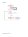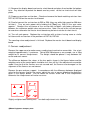
1
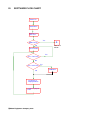
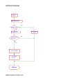
Adam Equipment
ADK PRECISION BALANCES
SERVICE MANUAL
ADAM EQUIPMENT CO. LTD.
P.N. 3278, Rev. B3, July 2007
@Adam
Equipment Company 2007
1
@Adam
Equipment Company 2007
2
ADK SERIES
SERVICE MANUAL
ELECTRONIC INDUSTRIAL BALANCE
TABLE OF CONTENTS
I.
II.
III.
IV.
V.
VI.
GENERAL DESCRIPTION
WORKING PRINCIPLE
SOFTWARE FLOW CHART
BASIC OPERATIONS AND PERFORMANCE TEST
TRIAL RUN & TEST
REPAIR
I.
GENERAL DESCRIPTION
The ADK balances include modern microprocessor control of the weighing process using
a rugged and sensitive mechanical design. In addition, its built-in underhook system can
also be used in dry specific gravity weighing. A bi-directional RS-232 interface is available
to connect with external equipment.
Technical Data
Model
Max. Capacity (kg)
Readability d=
Repeatability (S.D.)
Linearity (±)
Pan size
Weight
Overall Dimensions
Temperature
Power supply
ADK 10
10
0.1g
0.1g
0.2g
ADK 20
20
0.1g
0.1g
0.2g
340 x 300mm
18 kg
314 x 460 x 164mm
5ºC - 30ºC
230 / 115 VAC
Note: The manual should be read with the operation manual as a reference.
II.
WORKING PRINCIPLE
1.
Working Principle
These electronic balances rely on electromagnetic force restoration. The basic principle is
to generate a force by applying a current through a coil immersed in a magnet field. This
force is used to balance a force due to the sample weight placed on the balance. The
weighing system consists of a two-stage lever system and a photo-electric device used to
monitor the movement of the force coil. The two-stage lever system makes it possible to
realise a high capacity balance within a limited volume. The photo-electric device consists
of a fixed light source, a photo-electric detector and a moveable optical grating connected
to the force coil.
During operation the sample is placed onto the pan, a displacement will be made by the
optical grating attached to the coil and thus the photo-electric device will sense an electric
current which is correlated to the position of the grating. The signal is power amplified by
a pre-amplifier and a regulation circuit and a current increase is fed back to the force coil
which increases the electromagnetic force towards the direction opposite the displacement
direction. In this way the coil brings the photoelectric device back to the balanced position
where the weight of sample gets balanced with the electromagnetic force. The current of
the force coil is turned into numerical signal via an A/D converter which is then sent to the
microprocessor for data treatment. Final result will be displayed and printed out if the RS232 interface is active.
@Adam Equipment Company 2007
2
2.
Rear Panel Switch and Display PCB Dip-switch functions
The rear panel has a toggle switch with 2 functions when in test mode. In one position the
display indicates the balance zero-point value and in the other position the display
indicates the value of the dip-switches on the display circuit board.
PROCEDURE
To view the zero weight value or the switch setting values hold the [Tare] key down at the
same time the balance is turned on until the display shows the message confirming the
model capacity (C20000). Press [Tare] and the display will show either the zero weight
value (approximately 350) or the value of the dip-switches on the display PCB, (default
401112). Move the switch on the rear panel to toggle between these displays.
Turn the balance off and then on again to return to normal weighing.
Modification of ZERO ValueThe zero weight value is normally 300 to 400. If the value is outside of this range it will be
necessary to determine the cause and correct the error as described in section V.1.
Modification of Dip Switch settingsThe default value is “401112”.
This value is determined by the position of the 8 switches on the display PCB. The
functions of the 8-digit dial switch are as follows:
Segment
Function
1
2
Averaging
Time
3
Display
Rate
4
5
6
Auto-Print
7
Stability
Band
Width
.
AVERAGING TIME
Set switches 1 and 2 to set the averaging time. Default is 4 seconds.
SEGMENT
1
2
On
On
On
Off
Off
On
Off
Off
@Adam Equipment Company 2007
3
Averaging Time
1 Sec.
2 Sec.
4 Sec.
6 Sec.
8
DISPLAY RATE
Set switches 3 and 4 to set the Display Rate. Default is “01” corresponding to On-Off.
On=0 and Off=1.
SEGMENT
3
On
On
Off
Off
4
On
Off
On
Off
Display Rate
Big Change
Small Change
1/8 Sec. ¼ sec.
¼ Sec. ½ sec.
¼ Sec.
½ Sec.
AUTO PRINT
Leave these switches in the Off-Off position. This function is not normally used.
STABLE BAND WIDTH
Set switches 7 and 8 to set the averaging time The width of the band used to determine
stability. The default value is 2 digits.
SEGMENT
7
8
On
On
On
Off
Off
On
Off
Off
Stable Band Width
±1 digit
±2 digit
±4 digit
±8 digit
This dip-switch can also be set by users in accordance with their own requirements and
then the set value may be different. Please note that there is a 6-digit dial switch on the
master circuit board. Do not change its set status.
@Adam Equipment Company 2007
4
III.
SOFTWARE FLOW CHART
Power On
Initialisation
Display Test
Ram Test
Yes
A
Mode Check
No
See Test
Mode
Tare Function
Yes
Press Tare Key?
No
Press CAL Key?
No
Treatment of
Displayed Date
Output Displayed
Date
@Adam Equipment Company 2007
5
Yes
Calibration
INTERRUP PROGRAM
Interrupt
Routine
Indication Section/
Digit Processing
Yes
Mode Check
No
Accumulated
Counting Value
Accumulation =
125 values
Store Counting
Value
No
Yes
Check Stability
Averaging
Process
Return
@Adam Equipment Company 2007
6
TEST MODE
A
Indicate balance
model
No
Press TARE key?
Yes
Rear Panel
switch
Position 1
Position 2
Display Dip-switch
value
@Adam Equipment Company 2007
7
Display A/D
Count value
IV.
BASIC OPERATION AND PERFORMANCE TEST
The balance should be placed in a suitable environment to ensure normal operation and
accurate weighing:
Place the balance on a stable and clean working table.
Keep the working table away from vibration and air flow interruption.
Avoid direct sunlight on the balance.
Keep the balance far away from air conditioning or other thermal source such as central
heaters.
Keep the balance far away from magnetic matter and equipment which may possibly
involve a magnetic field such as x-ray or welders.
Do not put the balance to high temperature condition for long duration.
Do not use the balance in any area with a risk of explosion.
The optimum working temperature of the balance is 20°C±5°C at a relative humidity of 50
- 60%.
Position the balance as required. Adjust the levelling feet. Put the pan and the pan
support on the balance. Turn on main power. Preheat for one hour before doing the
basic operation or performance test.
PROCEDURE
Press the [Tare] key to zero the balance before weighing. Wait for an indication of 0
which indicate that the zero point of the balance has been stabilised.
SPAN CALIBRATION
Span calibration may be done at any time. Prepare a standard weight equal to the
maximum capacity before calibration. The weight should be of OIML Class F2 or better
for best accuracy.
Press the [Cal] key, an indication of “CAL 0.0g” will be displayed. Gently put the
calibration weight on the pan, there will be a value of the weight displayed. For example,
with model ADK - 20, “C20001.0” will be displayed. Wait until the indication is stabile.
Then press the [Cal] key. There will be an indication of “CAL END” and the span
calibration weight. The calibration is finished. Remove the weight from the balance.
Check the span calibration. Zero the balance and put the weight on the pan and see if the
indication is correct. Repeat the procedure one or two times if any error is found.
In case of a “CAL NO” indication being shown during the span calibration, it is necessary
to see if there is a big difference between indication and nominal value of the weight. If
there is a big difference, use the span calibration pot to make the indication to be close to
the nominal value of the weight as possible. Then calibrate with the [Cal] key as follows:To adjust the span pot: Remove the plastic cap of the pot on the right side of the balance
near the display.
@Adam Equipment Company 2007
8
Zero the balance and wait for stability, Put the span calibration weight on the pan.
Adjust the pot with a small screw driver to match the indication to he nominal value. If the
indication is less, turn the pot clockwise.
Again calibrate the balance with the [Cal] key. Replace the plastic cap after adjustment.
If “CAL NO” still appears, problem may be arising from an incorrect zero value for the A/D
converter.
PERFORMANCE CHECKS:
Off Center Loading (Corners) check:
Carry out the check on the four diagonal points of the pan using a weight of approximately
½ maximum. The values should agree within ±2 divisions (4d range between Max and
min readings).
Linearity check:
Select five weighing values within the range from zero to the maximum capacity.
weights should agree with the nominal values of the test weights within ±2 divisions.
The
Repeatability check:
Repeatedly weigh the span calibration weight for at least five times. The results should
agree with each other within 2 divisions.
If there are any errors noted during the performance test this may lead to a conclusion if
the balance needs a readjustment or repair. Generally errors found in linearity and off
center loading test can be corrected through readjustment.
Poor repeatability and poor stability, abnormal indications or abnormal operations are
malfunctions which need to be corrected by repair.
@Adam Equipment Company 2007
9
V.
TRIAL RUN & TEST
1.
Re-adjustment of zero value
Setting of the zero value influences the readability and capacity in display. A too small
zero value setting will result in the display showing a “-P “ indication whereas a too big
one will result in a “+E “ indication at full capacity.
To set the zero value:
Turn the main power off.
Press the [Tare] key, turn on main power on. The model of balance - C20000.0 will be
displayed for one or two seconds after all the segments lighting up. Press the [Tare] key
again. The zero value will be displayed.
Normal Zero values are from 250 to 350. Any zero value out of this range may be
corrected by adjusting the balance weight position as described below:
(1) Turn off the main power. Remove the pan and pan support. Remove the upper case
by unfastening the four fixing screws.
(2) Now the display board, master circuit board, power board, transformer and the whole
sensor mechanism are visible.
(3) Lift up the bottom case. You can see five M5 inner hexagonal screws connecting the
sensor to the bottom case. Unfasten the screws, remove and put the sensor and the
bottom case on a clean and stable table.
(4) Turn over the sensor and gently put it on the table, you will see the lower flexible
bearing assembly and the counter-balance weight (see figure 2).
(5) If the zero value is too large (>350), unfasten the locking screws and move the
counter-balance weight away from the core of the balance. In case of a too small zero
value move the counter-balance towards the core. Fasten the screws after readjustment.
(6) Turn back the sensor as normal. Put the pan and pan support on the balance. Check
the zero counting value again. Repeat the readjustment if the zero counting value is still
unsatisfactory until a satisfactory one is achieved.
Now the readjustment of zero counting value is finished. Turn off main power, replace the
sensor in the bottom case and fasten the five screws.
Place the pan and pan support on the balance. Press [Tare] and then turn on main power
and wait until the zero value is displayed. Put the maximum capacity weight on the pan.
Note the displayed value. The difference between maximum and zero values should be
3200±5 for model ADK-20 and 1660±5 for model ADK-10.
If the differences are not as given above, readjust as follows:
Turn off the power.
@Adam Equipment Company 2007
10
(1) Remove the display board and master circuit board and place them beside the bottom
case. Pay attention to protect the boards and any metal so that no short-circuit will take
place.
(2) Prepare a precision resistor box. Check and remove the black matching resistors from
R37-38, R57-60 on the master circuit board.
(3) Parallel connect the resistor box to R35 or R36 (they are white high precision 500 ohm
resistors). Turn on main power while holding the [Tare] key. Wait till the zero value
appears. Readjust the resistance of the resistor box to obtain satisfactory differences
between the maximum weight value and zero value. Note: Do not let the resistor box go
to zero ohms otherwise the master circuit board may be burnt out due to short circuit.
(4) Turn off main power. Replace the resistor box with resistors having same or similar
resistance with resistor box in the positions of R37-38, R57-60.
The counting value readjustment is finished. Replace the master circuit board and display
board.
2. Corners readjustment
Remove the upper case to make corners readjustment mechanism accessible. Use a test
weight of approximately ½ maximum. Taking ADK-20 balance as an example, use a 10kg
weight for its corners readjustment. The weight should be placed ½ way between the
center and each corner.
The difference between the values at the four points shown in the figures below and the
weighing value at the central point should be less than ±0.2g. If the adjustments cannot be
made it may be that the flexures are not secured well, the flexures are damaged or the
alignment of the flexures are not correct.
Remove the pan and pan support. In accordance with the difference between displayed
value for the corners and for the centre, adjust the nuts at corner following the directions
given in the figures below. Do not rotate the central screw rod in the readjustment
otherwise the readjustment will make no sense.
Front
Slightly untighten both locking nuts. Turn both adjustment nuts clockwise.
@Adam Equipment Company 2007
11
Front
Slightly untighten the locking nut on the left. Turn the adjustment nut clockwise. Turn the
adjustment nut on the right anticlockwise then slightly tighten the locking nut on the right.
Front
Turn the adjustment nut on the left anticlockwise and then slightly tighten the locking nut.
Turn the adjustment nut on the right clockwise after slightly untightening the locking nut on
the right.
Front
Turn both nuts anti-clockwise. Then slightly tighten the locking nuts.
@Adam Equipment Company 2007
12
3. Linearity readjustment
The linearity of the scale can be seen by placing 4 to 6 weights of approximately equal
value on the balance. The results of each weighing should agree with the nominal value
of the weights within ±2d.
A balance having a poor linearity may be compensated to a tolerance of ±0.2g by
readjusting the linearity potential as follows:
(1) Turn on main power and allow the balance to warm up. Remove the upper case of the
balance. Put the pan and pan support on the balance.
(2) Carry out a span calibration with a maximum capacity weight. Remove the weight. Put
a ½ maximum weight on the pan. Record the indication.
(3) Remove the ½ maximum weight and the pan. Four adjustable pots can be seen on
the right side of the master circuit board, among them R15 (200K) is a linearity potential.
Turn the pot clockwise if the indication was less than the actual weight and turn it
anticlockwise if the indication was greater than the actual. The pot will be used to bring
the ½ maximum indication as close as possible to the actual value.
(4) Put the pan on the balance. Zero the balance. Make a span calibration. Again put a
½ maximum weight on the pan to see if the readjustment is effective. If the tolerance is
still unsatisfactory, repeat procedure (3) until a satisfactory result is achieved.
(5) Verify the adjustment through the complete weighing range. If necessary carry out
mini-readjustment as described above until each test point (at least five points) in the
range of from zero to capacity is acceptable.
@Adam Equipment Company 2007
13
VI. REPAIR
Those balances which have failed to carry out normal operation or whose performance
fails to meet requirements after repeated readjustment should be repaired.
The ADK series of balance has a steady and stable mechanical structure so that
malfunctions of balance are generally caused by electric systems or damage to the
flexures. After any repair some characteristics such as temperature compensations, zero
counting value and off center-loading could be changed. Any balance being repaired
should be compensated and monitored to check their performance for a period of time
before putting them into normal use.
Troubleshooting and repair of common malfunctions:
1. No indication after power on.
Check and replace the fuse as necessary.
Check if there is a poor contact in power switch.
Check if the connection between power cord and power switch is broken or in poor
contact.
Check the power voltage of the indication board with an voltmeter:
Voltage of pin 2 of J3 : Vcl2 - +5V ±0.2V
Voltage of pin 3 of J3: VEE - -27V ±2V
Voltage between pin 6 and pin 7: 3.9VAC ±0.2V
Normal voltages always suggest a malfunction in the indication board.
B
B
B
B
B
B
B
B
If the above measurement shows abnormal voltage or partly abnormal it is required
to check the voltage of power board and the input and output voltage of the
transformer. If the voltage of the transformer is correct, the malfunction is with the
power board, or vice versa.
Check if the capacitors C1 - C4 on the calibration board are damaged.
B
B
B
B
2. No indication in some segments.
Check for a poor contact at cable plug J3 of the indication board.
Any breakage of V1 - V4
I.C. packages on the indication board may lead to
indication loss of segments.
Breakage in V15 - V17, V6, V12, V11 I.C. package may lead to master board
malfunctions.
B
B
B
B
B
B
B
B
B
B
B
B
B
B
B
B
3. “Error” indication frequently appears or indicates randomly
Master board malfunction most possibly, trouble in digital circuits.
4. Balance does not tare when TARE key is pressed.
TARE key is broken
A wrong setting in the 7-digit dial switch of the indication board
Indication board malfunction
@Adam Equipment Company 2007
14
5. “-E” indication keeps unchanged.
Master board malfunctions due to breakage in Q1, Q2, Q4, V2, V3, V4 of the
analogue circuit or breakage in V7, V3, V13, V14 I.C. packages of the digital circuit.
There is friction between magnet and coil or between limit stop and limit nut.
Return the balance to the manufacturer to solve the problem.
B
B
B
B
B
B
B
B
B
B
B
B
B
B
B
B
B
B
B
B
6. “-P” indication keeps unchanged.
Zero counting value is set too low. Readjust it.
Pan support is placed incorrectly. Make all the four feet of the pan support align to
its base.
Breakage in Q1, Q2, Q3, Q4, V1, V3, V4 of the analogue may lead to master board
malfunctions
Vertical Flexure is broken.
B
B
B
B
B
B
B
B
B
B
B
B
B
B
Replace the damaged vertical flexure as follows:
(1) Remove the sensor mechanism from bottom case, remove the cable connecting
master board from the sensor and place the sensor on the work table.
(2) It can be seen from the rear of the sensor that there is a flexure on the gravity beam
connecting the machine core. Unscrew the locking screw on the upper end of the flexure.
(3) Unscrew the screws connecting the horizontal flexures on the upper and lower flexible
bearing assemblies to the gravity beam. Remove the gravity beam and its support.
(4) Unscrew the lower screw of the vertical flexure. Replace the broken flexure with a new
one.
(5) Replace the lower screws of the flexure. Check the flexure on the table with a square
ruler to ensure it is in a vertical condition.
(6) Connect the gravity beam and its support as a whole to the upper and lower flexure
beam bearing assemblies. Do not tighten all screws at this time. Place the sensor on the
table. Check the gravity beam with a square ruler to keep it vertical and then tighten the
screws of the upper and lower flexible bearing assemblies.
(7) Replace and tighten the upper connecting screw of the vertical flexure.
Now the replacement of the spring is finished.
(8) Check the alignment of all the parts, the position of the stop plates and check all
screws are tight.
@Adam Equipment Company 2007
15
7. “0.0” indication is unchanged even when the balance is loaded.
Check if the 12-core calibration cable is in poor contact or broken.
U2 on calibration board is damaged (see figure 1 for the position).
B
B
8. Poor stability and poor repeatability.
Master board malfunctions such as breakages in Q1, Q5, Q6, V4 and C18.
Magnet of the machine core is contaminated by dirt. Disassembly and clean the
magnet. (Note: this should be done by returning the balance to the manufacturer).
B
B
B
B
B
B
B
B
B
B
9. Incorrect indications.
Balance is not calibrated correctly. Recalibrate it.
Malfunctions in master board digital circuit
10. Corners calibration cannot be carried out.
Flexures on the horizontal bearing assemblies are broken or influenced by stress
during installation.
Check and retighten untightened screws in machine core.
These are the common troubles, their possible reasons and methods of repair of ADK
series balance. Of course, it is impossible to include all the types of troubles and their
miscellaneous reasons in this manual.
Some troubles such as the replacement of flexures, disassemble and assemble of the
machine core, cleaning of the magnet should be repaired by experienced serviceman or
return the balance to the manufacturer for repair.
Electric circuit boards are available from Adam Equipment for damaged circuit boards.
If it is necessary to replace the master circuit board, follow these guides. Use a ohmmeter
to measure the resistance of the pots of R22 and R51, record the results for later use.
B
B
B
B
Check the resistance of resistor R23 (2.2K). Remove it for later use if its resistance is
different from that specified in the circuit diagram. If you have difficulty with the
readjustment of counting value remove the matched black precision resistors on R37 - R38,
R57 - R60 and replace them after the replacement of master circuit board and then reset
pots R22 and R51 to the same values as was used on he old circuit board.
B
B
B
B
B
B
B
B
B
B
B
@Adam Equipment Company 2007
16
B
B
B
Manufacturer’s Declaration of Conformity
This product has been manufactured in accordance with the harmonised European standards,
following the provisions of the below stated directives:
Electro Magnetic Compatibility Directive 89/336/EEC
Low Voltage Directive 73/23/EEC
Adam Equipment Co. Ltd.
Bond Avenue, Denbigh East
Milton Keynes, MK1 1SW
United Kingdom
FCC COMPLIANCE
This equipment has been tested and found to comply with the limits for a Class A digital device,
pursuant to Part 15 of the FCC Rules. These limits are designed to provide reasonable protection
against harmful interference when the equipment is operated in a commercial environment. The
equipment generates, uses, and can radiate radio frequency energy and, if not installed and used in
accordance with the instruction manual, may cause harmful interference to radio communications.
Operation of this equipment in a residential area is likely to cause harmful interference in which case
the user will be required to correct the interference at his own expense.
Shielded interconnect cables must be employed with this equipment to insure compliance with the
pertinent RF emission limits governing this device.
Changes or modifications not expressly approved by Adam Equipment could void the user's authority
to operate the equipment.
WEEE COMPLIANCE
Any Electrical or Electronic Equipment (EEE) component or assembly of parts intended to be
incorporated into EEE devices as defined by European Directive 2002/95/EEC must be recycled or
disposed using techniques that do not introduce hazardous substances harmful to our health or the
environment as listed in Directive 2002/95/EC or amending legislation. Battery disposal in Landfill
Sites is more regulated since July 2002 by regulation 9 of the Landfill (England and Wales)
Regulations 2002 and Hazardous Waste Regulations 2005. Battery recycling has become topical
and the Waste Electrical and Electronic Equipment (WEEE) Regulations are set to impose targets
for recycling.
T
T
@Adam Equipment Company 2007
ADAM EQUIPMENT is an ISO 9001:2000 certified global organisation with more than 30 years
experience in the production and sale of electronic weighing equipment. Products are sold through
a world wide distributor network supported from our company locations in the UK, USA, SOUTH
AFRICA and AUSTRALIA.
ADAM’s products are predominantly designed for the Laboratory, Educational, Medical and
Industrial Segments. The product range is as follows:
-Analytical and Precision Laboratory Balances
-Counting Scales for Industrial and Warehouse applications
-Digital Weighing/Check-weighing Scales
-High performance Platform Scales with extensive software
features including parts counting, percent weighing etc.
-Crane scales for heavy-duty industrial weighing
-Digital Electronic Scales for Medical use
-Retail Scales for Price computing
Adam Equipment Co. Ltd.
Bond Avenue
Milton Keynes
MK1 1SW
UK
Adam Equipment Inc.
26, Commerce Drive
Danbury, CT
06810
USA
Adam Equipment S.A. (Pty) Ltd.
7 Megawatt Road,
Spartan EXT 22, Kempton Park,
Johannesburg
Republic of South Africa
Adam Equipment (S.E. ASIA)
Pty Ltd.
2/71 Tacoma Circuit
Canning Vale, Perth
Western Australia
Tel:+44 (0)1908 274545
Fax: +44 (0)1908 641339
Tel: +1 203 790 4774
Fax: +1 203 792 3406
Tel: +27 (0)11 974 9745
Fax: +27 (0)11 392 2587
Tel: +61 (0) 8 6461 6236
Fax: +61 (0) 8 9456 4462
E-mail:
[email protected]
HTU
UTH
E-mail:
[email protected]
HTU
E-mail:
[email protected]
HTU
UTH
E-mail:
[email protected]
UTH
HTU
© Copyright by Adam Equipment Co. Ltd. All rights reserved. No part of this publication
may be reprinted or translated in any form or by any means without the prior permission of
Adam Equipment.
Adam Equipment reserves the right to make changes to the technology, features,
specifications and design of the equipment without notice.
All information contained within this publication is to the best of our knowledge timely,
complete and accurate when issued. However, we are not responsible for
misinterpretations which may result from the reading of this material.
The latest version of this publication can be found on our Website.
Visit us at www.adamequipment.com
HTU
@Adam Equipment Company 2007
UTH
UTH