1
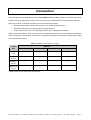
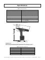
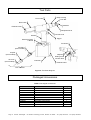
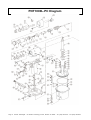
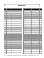
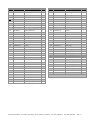
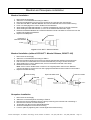
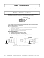
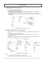
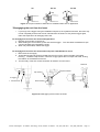
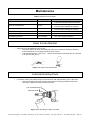
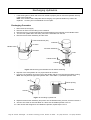
POP ™ NUT Tool PNT1000L-PC Maintenance Manual Contents Introduction ............................................................................................................................................... 3 Safety Instructions .................................................................................................................................... 4 Specifications............................................................................................................................................ 5 Tool Parts .............................................................................................................................................. 6 Packaged Accessories .......................................................................................................................... 6 PNT1000L-PC Diagram............................................................................................................................ 8 Parts List................................................................................................................................................. 10 Tool Setup............................................................................................................................................... 12 Mandrel and Nosepiece installation .................................................................................................... 13 Basic Tool Operation............................................................................................................................... 14 Mandrel & Nosepiece Adjustment ....................................................................................................... 14 Setting Force Valve Spring Selection.................................................................................................. 15 Tool Operation..................................................................................................................................... 16 Setting Force Adjustment........................................................................................................................ 18 Adjustment for Standard POP NUTs™ ............................................................................................... 18 Adjustment for ST & Thin Wall POP NUTs™ ...................................................................................... 18 Adjustment of Setting Force................................................................................................................ 18 Maintenance ........................................................................................................................................... 19 Clean & Lube Mandrel ........................................................................................................................ 19 Lubricate Rotating Parts...................................................................................................................... 19 Recharging Hydraulics ........................................................................................................................ 20 Troubleshooting ...................................................................................................................................... 22 Safety Data ............................................................................................................................................. 24 EC Declaration of Conformity ................................................................................................................. 26 Page 2 Emhart Teknologies - 50 Shelton Technology Center, Shelton CT 06484 - Tel. (203) 924-9341 - Fax (800) 225-5614 Introduction The PNT1000L-PC is a lightweight tool for installing POP® brand POP NUT™ blind rivet nuts and other blind threaded inserts by adjusting the setting force to the insert being installed rather than stroke like traditional blind rivet nut tools. Controlling the setting force has the following benefits: • No stroke adjustment is needed for the same nut in multiple application grips. • Eliminated application & nut damage due to “double stroking”. • Proper set achieved even with a small gap between the nut flange and Nosepiece. Table 1 lists the POP NUT™ blind rivet nuts that can be fastened using this tool. The Nosepiece and Mandrel must be changed to fit some sizes of POP NUT™. (See Table 5, Mandrel and Nosepiece Requirements table in the Specification section) Table 1: POP NUT™ blind rivet nut range Thread Size Material Aluminum M6X1.0 ¼-20 Steel Steel RLT Stainless M8X1.25 5/16-18 M10X1.5 3/8-16 M12X1.75 1/2-13 * * * Need to set tool at 0.55 MPa [80 psi] Minimum. Emhart Teknologies - 50 Shelton Technology Center, Shelton CT 06484 - Tel. (203) 924-9341 - Fax (800) 225-5614 Page 3 Safety Instructions TO INSURE PROPER FUNCTIONING AND SAFE OPERATION READ THIS MANUAL CAREFULLY BEFORE SETTING UP OR OPERATING THE POP NUT SERIES TOOLS DEFINITIONS: • CAUTION! – Failure to observe this precaution could result in physical damage or minor injury. • WARNING! – Failure to observe this precaution could result in physical damage, serious injury or even death. CAUTION! 1. DO NOT use this tool in a manner other than that recommended by Emhart Teknologies. 2. DO NOT modify the tool in any way. Modification will void any applicable warranties and could result in damage to the tool or physical injury to the user. 3. Disconnect air supply when adjusting, servicing or removing any part of the tool. 4. Trained personnel must perform tool repair and/or maintenance at prescribed intervals. 5. Only use genuine Emhart Teknologies parts for tool maintenance and repair. 6. Do not operate the tool with the Nose Housing removed. 7. Keep fingers away from the front of the tool when connecting the air supply or using the tool. 8. Do not attempt to turn the Mandrel when the air supply is connected. 9. Keep hair, fingers and loose clothing away from moving parts of the tool. 10. Do not direct tool exhaust towards anyone. The tool uses lubricated air and may eject oil mist or debris. 11. Do not use organic solvents to clean the tool, this may damage the tool. 12. Wash hands thoroughly if exposed to hydraulic fluid or lubricant. WARNING! 1. DO NOT exceed the maximum recommended air pressure of 0.6 MPa (87 psi / 6.0 bar). 2. DO NOT point the tool at anyone when in use. 3. Always wear safety rated eye protection when using or when near a tool in use. 4. Always wear safety rated hearing protection when using or when near a tool in use. 5. Inspect the tool and connections for damage, worn or loose parts before connecting to the air supply. If damaged, stop use immediately and have the tool repaired or replaced. 6. This tool is not designed for use in explosive atmospheres. Page 4 Emhart Teknologies - 50 Shelton Technology Center, Shelton CT 06484 - Tel. (203) 924-9341 - Fax (800) 225-5614 Specifications Table 2: Tool Specifications Feature Specification Weight 2.77 kg (6.11 lbs) Overall length 315 mm (12.4 in) Overall height 295 mm (11.6 in) Tool Stroke 1.3 – 10.5 mm (0.05 – 0.413 in) Pulling Force 24.3 kN @ 5.0 bar ( 5463 lbf @ 72.5 psi) Air Supply 0.5 – 0.6Mpa (5 – 6 bar) (72.5 – 87 psi) Hydraulic Oil See Table 3, Specified Hydraulic Oils Setting capacity See Table 1, POP NUT™ blind rivet nut range LAeq,T = 80.3 dB(A), LWA = 88 dB(A), LPeak = 106.8 dB(C) 2 2 0.40 m/s , Time to 2.5 m/s > 24hrs (EAV) Tool Noise Level* Tool Vibration Level *Emhart recommends the use of hearing protection when operating this tool (71) 315 (38) φ28 φ31.5 295 106 Figure 1: Tool Dimensions (mm) Hydraulic oil Use only Emhart Teknologies specified hydraulic lubrication oils as shown in Table 3. Use of any other oil could reduce the tool performance or even damage the tool. Table 3: Specified Hydraulic Oils Company name Mobile Shell Idemitsu Cosmo Esso Nisseki Mitsubishi Product name Mobile DTE26 Shell Telus Oil C68 Daphne Hydro 68A Cosmo Olpas 68 Telesso 68 FBK RO68 Diamond Lube RO68 (N) Emhart Teknologies - 50 Shelton Technology Center, Shelton CT 06484 - Tel. (203) 924-9341 - Fax (800) 225-5614 Page 5 Tool Parts Nose Housing Front Case Lock Nut Rear Case Mandrel Exhaust Holes Nosepiece/Anvil Handle Control Knob Trigger Swivel Air Fitting ¼ NPTF Fill Screw Air Fitting (Not Included) Coupler (Not Included) Adjuster Setting Force Control Valve Air Hose (Not Included) Chamber Exhaust Holes Not included Figure 2: Tool Parts Diagram Packaged Accessories Table 4: Packaged Accessories Part No. PNT1000L-PC-T PNT600-132 PNT600-133 PNT600-136 DPN239-139 DPN907-006 DPN277-185 FG2245 FG2268 FG2222 Page 6 Item PNT1000L-PC POP NUT™ Tool Hook Hex wrench 1.5 mm Hex wrench 3 mm Hex wrench 4 mm Cap screw M4 X 20 POP NUT™ Mandrel Release Operating Instructions Maintenance Manual Warranty Card Qty 1 1 1 1 1 1 1 1 1 1 Emhart Teknologies - 50 Shelton Technology Center, Shelton CT 06484 - Tel. (203) 924-9341 - Fax (800) 225-5614 Table 5: Mandrel and Nosepiece requirements Mandrel Adapter Flat Nosepiece Thick Wall I.D. (Std & ST) Mandrel M8X1.0 Thread size POP NUT Thread size Part No. I.D. M6X1.0 PNT1000-02-6 φ6.1 M8X1.25 PNT1000-02-8 φ8.1 M10X1.5 PNT1000-02-10 φ10.1 M12X1.75 PNT1000-02-12 φ12.1 1/4-20 PNT1000-02-420 φ 6.5 5/16-18 PNT1000-02-8 φ8.1 3/8-16 PNT1000-02-10 φ10.1 1/2-13 PNT1000-02-813 φ12.8 Piloted Nosepiece Thin Wall Part No. PNT1000-58 - PNT1000-58 - Thread size PNT600-01-6 M6X1.0 PNT600-01-8 M8X1.25 PNT1000-01-10A M10X1.5 PNT1000-01-12A M12X1.75 PNT600-01-420 1/4-20 PNT600-01-518R 5/16-18 PNT1000-01-616R 3/8-16 PNT1000-01-813 1/2-13 Mandrel Adapter I.D. (TK,TL,TH) Part No. Mandrel M8X1.0 Thread size POP NUT Thread size Part No. I.D. M6X1.0 PNT1000-02-6P φ6.1 M8X1.25 PNT1000-02-8P φ8.1 M10X1.5 PNT1000-02-10P φ10.1 M12X1.75 PNT1000-02-12P φ12.1 1/4-20 PNT1000-02-420P φ6.5 5/16-18 PNT1000-02-8P φ8.1 3/8-16 PNT1000-02-10P φ10.1 1/2-13 PNT1000-02-813P φ12.8 Part No. PNT1000-58 - PNT1000-58 - Part No. Thread size PNT600-01-6P M6X1.0 PNT600-01-8P M8X1.25 PNT1000-01-10P M10X1.5 PNT1000-01-12P M12X1.75 PNT600-01-420 1/4-20 PNT600-01-518 5/16-18 PNT1000-01-616 3/8-16 PNT1000-01-813 1/2-13 * Refer to the Tool Setup section for details of Nosepiece and Mandrel installation. Emhart Teknologies - 50 Shelton Technology Center, Shelton CT 06484 - Tel. (203) 924-9341 - Fax (800) 225-5614 Page 7 PNT1000L-PC Diagram Page 8 Emhart Teknologies - 50 Shelton Technology Center, Shelton CT 06484 - Tel. (203) 924-9341 - Fax (800) 225-5614 Emhart Teknologies - 50 Shelton Technology Center, Shelton CT 06484 - Tel. (203) 924-9341 - Fax (800) 225-5614 Page 9 Parts List Item Part No. Description Qty Item Part No. Description 1 PNT600-01-8 Mandrel M8 1 2 3 PNT1000-02-8 Nose Piece M8 PNT1000-03 Lock Nut 4 PNT1000-04 5 48 PNT600-74 EXT Valve Case 2 1 49 DPN901-012 Spring 2 1 50 DPN900-051 O-Ring 2 Nose Housing 1 51 PNT600-77 EXT Valve Rod 2 PNT1000-05 Lock Pin 1 52 DPN900-052 O-Ring 1 6 PNT1000-06 Lock Pin Pusher 1 55 PNT1000-33 SV/HL Tube 1 7 DPN900-046 O-Ring 1 56 PNT1000-34 HU/HL Tube 1 8 PNT1000-07 Lock Pin Holder 1 59 DPN900-053 O-Ring 6 9 DPN901-013 Spring 1 60 DPN902-001 Retaining Ring 1 10 PNT1000-08 Spin Pull Head 1 61 PNT1000-38 S Valve Rod 1 11 PNT1000-09 Spin Pull Head Case 1 62 DPN277-071 Flat Head Cap Screw 1 12 PNT1000-10 Bit 1 63 DPN277-011 Trigger 1 15 DPN277-322 Front Case 1 64 PNT1000-39 SV/HU Tube 2 16 PNT1000-14 Mast Housing 1 65 DPN907-012 Socket Head Cap Screw 1 17 PNT1000-15 Housing Lock 1 66 DPN239-047 Fill Screw 1 18 DPN901-018 Return Spring 1 67 DPN900-033 O-Ring 3 19 PNT1000-17 Rod Seal Receiver 1 68 PNT1000-40A T Valve Rear Case 1 20 DPN908-015 Scraper 1 69 PNT1000-41 T Valve Center Case 1 21 DPN908-016 BU-Ring 1 70 PNT1000-42 T Valve Rod 1 22 DPN908-019 Rod Seal 1 71 PNT1000-43 T Valve Front Case 1 25 DPN908-014 Piston Seal 1 72 DPN900-013 O-Ring 6 26 DPN908-017 BU-Ring 1 73 DPN900-014 O-Ring 1 27 DPN900-047 O-Ring 1 74 PNT600-91 T Valve Front Piece 1 28 DPN277-187 Handle Upper 1 75 PNT1000-44 T Valve Lock 1 29 PNT600-20 Start Bar 1 76 DPN901-014 Spring 1 30 PNT1000-21 Rear Case 1 77 DPN900-011 O-Ring 2 31 DPN907-007 Socket Head Cap Screw 2 78 DPN900-017 O-Ring 8 32 DPN907-006 Socket Head Cap Screw 1 79 PNT1000-45 T Valve Cap 1 33 PNT1000-22 End Cap 1 80 DPN277-323 T Valve Push Rod 1 34 DPN900-048 O-Ring 12 81 DPN277-304 Cylinder 1 35 PNT1000-23 HU/EC Tube 2 82 DPN277-324 Control Knob 1 36 PNT1000-24A End Cap Tube 2 83 DPN905-004 Socket Set Screw 1 37 DPN907-008 Socket Head Cap Screw 7 84 PNT1000-59 Cap Screw 1 38 DPN900-049 O-Ring 1 85 DPN905-005 Socket Set Screw 3 39 DPN277-189 Handle 1 86 DPN907-005 Socket Head Cap Screw 1 40 PNT1000-26A Sleeve 1 87 DPN907-009 Socket Head Cap Screw with Flange 4 41 DPN908-020 Rod Seal 1 88 PNT1000-49A Plug 1 42 DPN908-018 BU-Ring 1 89 DPN900-054 O-Ring 1 43 DPN277-188 Handle Lower 1 90 DPN900-006 O-Ring 2 44 DPN900-050 O-Ring 1 91 PNT1000-50A Valve Lower 1 45 PNT1000-28 Ram Seal Receiver 1 94 PNT1000-54 Valve Stopper 2 46 DPN277-180 Chamber 1 95 PNT1000-55A R Joint 1 47 DPN902-005 E Retaining Ring 2 96 PNT1000-56A R Joint Adapter 1 Page 10 Emhart Teknologies - 50 Shelton Technology Center, Shelton CT 06484 - Tel. (203) 924-9341 - Fax (800) 225-5614 Qty Item Part No. Description Qty Item Part No. Description 97 PNT1000-57 R Joint Spacer 1 98 PNT1000-58 Mandrel Adapter M6,M8 133 PNT600-98B 139 DPN277-184 140 PNT1000-11 141 Qty 110 PNT600-110 Casing 1 1 111 PNT600-111 Ball Bearing 1 M Valve End 1 112 PNT600-112 Rear Plate 1 Spring Lock Washer 1 113 PNT600-113 Rotor 1 Joint Assembly 1set 114 PNT600-114 Blade 4 PNT1000-18 Hydraulic Piston Assembly 1set 115 PNT600-115 Spring Pin 1 142 FAN277-194 Air Piston Assembly 1set 116 PNT600-116 Cylinder 1 143 PNT1000-35 S Valve Assembly 1set 117 PNT600-117 Front Plate 1 144 FAN277-195 Valve Upper Assembly 1set 118 PNT600-118 Ball Bearing 1 145 PNT600-34 Truss Head Screw 1 119 PNT600-119 Spacer 1 146 DPN277-309 Fitting 2 120 PNT600-120 Sun Gear 1 149 DPN277-327 Air Tube 1 121 PNT600-121 Planet Gear 6 151 FAN277-311 Setting Force Control Valve 1set 122 PNT600-122 Needle Pin 6 152 DPN277-306 Adjuster 1 123 PNT600-123 Gear Cage & Gear 1 153 DPN901-023 Valve Spring 1 124 PNT600-124 Spacer 1 155 DPN277-305 Valve 1 125 PNT600-125 Internal Gear 1 156 DPN900-015 O-Ring 1 126 PNT600-127 Gear Cage 1 157 DPN905-006 Socket Set Screw 1 127 PNT600-128 Spacer 1 158 DPN277-307 Valve Case 200 PNT600-200 Air Motor 49 DPN901-012 73 1 128 PNT600-129 Ball Bearing 1 1set 129 DPN902-003 Retaining Ring 1 Spring 1 130 DPN902-004 Retaining Ring 1 DPN900-014 O-Ring 2 90 DPN900-006 O-Ring 2 32 DPN907-006 Socket Head Cap Screw 1 99 DPN900-042 O-Ring 1 134 PNT600-132 Hook 1 100 DPN277-177 Flat Head Screw 1 135 PNT600-133 HS Screw Key, 1.5mm 1 101 PNT600-101A Motor Case End Plate 1 136 PNT600-136 HS Screw Key, 3mm 1 102 DPN900-043 O-Ring 1 137 DPN239-139 HS Screw Key, 4mm 1 103 PNT600-103 M Valve Rod 1 138 DPN277-185 POP NUT Mandrel Release 1 104 PNT600-104 Motor Case End 1 147 PNT1000-01-10A Mandrel, M10 1 105 PNT600-105 Washer 1 148 PNT1000-02-10 Nose Piece, M10 1 106 DPN900-044 O-Ring 1 107 PNT600-107 O-Ring Holder 1 108 DPN900-045 O-Ring 1 109 DPN902-002 Retaining Ring 1 Accessories *See Table 5 for additional Mandrels and Nosepieces Emhart Teknologies - 50 Shelton Technology Center, Shelton CT 06484 - Tel. (203) 924-9341 - Fax (800) 225-5614 Page 11 Tool Setup Initial Setup 1. Check that the correct Nosepiece and Mandrel are fitted for the POP NUT™. See the Basic Tool Operation section for proper tool adjustment. 2. Connect an air fitting to the Swivel Air Fitting of the tool. The Swivel Air Fitting is a 1/4 NPTF thread. 3. Connect an Air Hose to the tool. 4. Connect an air filter, regulator and lubricator in the air line between the air supply and Air Hose connecting to the tool, within 3m [6 ft ] of the tool. 5. Adjust the air pressure supply and oil drip volume of the lubricator • Air Pressure: 0.5-0.6 MPa. (72.5-87 psi) • Oil drip volume: 1-2 drops/ 20 nuts fastened Figure 3: Tool Setup Note: Refer to the instruction manual for the Lubricator used for the proper adjustment method and lubrication oils to use relating to air motors. WARNING! Use an air hose with a rating of 1.0 MPa (145 psi / 10 bar) or greater maximum ordinary operating pressure. Also make sure the hose material is suitable for the operating environment (i.e. oil proof, wear and abrasion resistance etc.). For details, refer to your hose manufacturer's catalog. Page 12 Emhart Teknologies - 50 Shelton Technology Center, Shelton CT 06484 - Tel. (203) 924-9341 - Fax (800) 225-5614 Mandrel and Nosepiece installation Mandrel Installation 1. 2. 3. 4. 5. 6. 7. 8. Disconnect the Air Supply Select the correct Mandrel according to Table 5. Remove the Nosepiece from the tool by loosening the Lock Nut and unscrewing it. Insert the POP NUT™ Mandrel Release tool over the Mandrel and into the Nose Housing. Push in to disengage the Lock Pin Holder from the Mandrel. While holding the Mandrel Release in, unscrew the Mandrel by turning it counter-clockwise. While holding the Mandrel Release in, screw in the desired Mandrel until it stops. Release the Mandrel Release and rotate the Mandrel counter-clockwise to ensure the Lock Pin Holder has engaged the Mandrel. 9. Replace the Nosepiece. Mandrel POP NUT™ Mandrel Release PUSH Figure 4: POP NUT™ Mandrel Release Mandrel Installation (without POP NUT™ Mandrel Release, DPN277-185) 1. 2. 3. 4. 5. 6. Disconnect the Air Supply Select the correct Mandrel according to Table 5. Remove the Nose Housing from the tool to expose the Mandrel and Spin Pull Head Case. Pull the Lock Pin Holder back and unscrew the Mandrel by turning it counter-clockwise. While holding the Lock Pin Holder back, screw in the desired mandrel until it stops. Release the Lock Pin Holder. Note: If the Lock Pin Holder does not return to its original position then turn the Mandrel counter-clockwise to ensure the Lock Pin engages the Mandrel and the holder moves forward. 7. Replace the Nose Housing. Nose Housing Mandrel Spin Pull Head Case Lock Pin Holder Mandrel PULL Figure 5: Mandrel Installation Nosepiece Installation 1. 2. 3. 4. 5. 6. 7. Disconnect the Air Supply Select the correct Nosepiece according to Table 5. Remove the current Nosepiece from the tool by loosening the Lock Nut and unscrewing it. Remove the Lock Nut from the Nosepiece Thread the Lock Nut onto the desired Nosepiece Screw the Nosepiece into the Nose Housing Lock it in place by tightening the Lock Nut against the Nose Housing Emhart Teknologies - 50 Shelton Technology Center, Shelton CT 06484 - Tel. (203) 924-9341 - Fax (800) 225-5614 Page 13 Basic Tool Operation Before setting POP NUTs™ with this tool, refer to the Safety Instructions and Tool Setup sections of this manual to ensure safe and reliable tool operation. Mandrel & Nosepiece Adjustment 1. Verify that the correct Mandrel and Nosepiece are fitted to the tool for the desired POP NUT™ (See Mandrel and Nosepiece Requirements table in the Specifications section). Nosepiece/Anvil Lock Nut Figure 6: Nosepiece and Lock Nut 2. Loosen the lock nut on the tool and thread the Nosepiece all the way into the Nose Housing. 3. Thread the desired POP NUT™ onto the tool. Open End POP NUTs™ a. Thread the insert onto the mandrel until the Mandrel extends beyond the insert by approximately 1 full thread b. Unthread the Nosepiece until it is touching the flange of the insert c. Tighten the lock nut against the Nose Housing. Closed End POP NUTs™ a. b. c. d. Thread the insert onto the mandrel until it stops Unthread the insert on full turn (one thread pitch) Unthread the Nosepiece until it is touching the flange of the insert Tighten the lock nut against the Nose Housing. Open End Closed End One Thread One Thread Figure 7: Proper Mandrel and Nosepiece adjustment Page 14 Emhart Teknologies - 50 Shelton Technology Center, Shelton CT 06484 - Tel. (203) 924-9341 - Fax (800) 225-5614 Setting Force Valve Spring Selection • • There is one type of spring used with the PNT1000L-PC tool that covers the range of inserts indicated. Review the table below Valve Spring part number. Table 6: Setting Force Valve Spring for Standard & Thick Wall inserts Thread Size Thick Wall (Std & ST) M6 1/4-20 M8 5/16-18 M10 3/8-16 M12 1/2-13 Material Aluminum Steel RLT Stainless - DPN901-023 DPN901-023 DPN901-023 DPN901-023 DPN901-023 DPN901-023 DPN901-023 DPN901-023 DPN901-023 - DPN901-023* - DPN901-023 - - * Need to set tool at 0.55Mpa Minimum. Table 7: Setting Force Valve Spring for Thin Wall inserts (TK, TL, TH) Thin Wall (TK, TL, TH) Thread Size M6 1/4-20 M8 5/16-18 M10 3/8-16 M12 1/2-13 Steel DPN901-023 DPN901-023 DPN901-023 DPN901-023 20 mm [0.79 in] DPN901-023: Figure 8: Valve Spring Emhart Teknologies - 50 Shelton Technology Center, Shelton CT 06484 - Tel. (203) 924-9341 - Fax (800) 225-5614 Page 15 Tool Operation Loading the POP NUT™ onto the tool 1. Connect the air supply to the tool. 2. Thread the insert 1/4 turn onto the Mandrel. 3. Press the insert against the Mandrel as indicated and the Mandrel will spin, automatically threading the insert onto the Mandrel. 4. Keep pushing the insert onto the Mandrel until the Mandrel stops spinning. If the insert is not fully threaded, the setting stroke will be shortened by the gap between the head of the insert and the Nosepiece. OK Gap Not OK Figure 9: Loading the POP NUT™ onto tool Installing the POP NUT™ into the work piece 1. With the POP NUT™ mounted on the Mandrel, insert it perpendicularly into the hole of the work piece 2. Pull the trigger and hold it to install the insert 3. Keep trigger depressed until the Mandrel reverses direction and completely unthreads the Mandrel from the insert. 4. Lightly pull the tool away from the work piece as Mandrel is reversing to disengage it from the insert. 5. Once the tool is disengaged from the insert, release the trigger.* LIGHTLY PULL Trigger PULL HOLD RELEASE Work piece Figure 10: Setting the POP NUT™ Note: • • Fit the flange of the insert flat against the work piece. Do not tilt the tool. The tool must be perpendicular to the work piece. Page 16 Emhart Teknologies - 50 Shelton Technology Center, Shelton CT 06484 - Tel. (203) 924-9341 - Fax (800) 225-5614 OK Not OK Not OK Gap Figure 11: Proper insertion of POP NUT™ threaded inserts into an application *Disengaging the tool from the insert • If you let go of the trigger during the installation sequence, the hydraulics will reset, the insert may not set completely and the tool will not unthread from the insert. Do not pull the trigger again, follow the steps below to disengage the insert. To disengage the tool from the insert and application: 1. Depress and hold the Control Knob 2. While holding the Control Knob, press and hold the trigger. counter-clockwise and unthread the insert. 3. When fully unthreaded, release the trigger. This will cause the Mandrel to spin To disengage the tool from the insert and work piece if the Mandrel is stuck: 1. Disconnect the air supply 2. Thread the M4 x20 Cap screw provided with the tool, into the hole in the side of the Nose Housing. Thread the Cap screw in until if fits snugly against the inner Spin Pull Head, locking the rotatioin of the Mandrel to the tool. 3. Turn the body of the tool counter-clockwise to detach it from the insert. ROTATE Cap Screw Spin Pull Head 2. Trigger 1. Control Knob Nose Housing Figure 12: Disengaging the tool from the insert Emhart Teknologies - 50 Shelton Technology Center, Shelton CT 06484 - Tel. (203) 924-9341 - Fax (800) 225-5614 Page 17 Setting Force Adjustment Verify the proper Valve Spring is selected – See “Setting Force Valve Spring Selection“ Adjust the setting force of the tool according to insert size and thickness of work piece as indicated in the instructions below. Test 5 pieces before beginning production work to ensure proper setting of the POP NUT™. Proper setting force is critical: o Low setting Force results in insufficient stroke and clamping of the insert, leading to a Spin Out failure in the application o High setting force results in excess stroke and possible insert threads stripping and Mandrel damage • • • • Adjustment of Setting Force The following is the procedure for adjusting the Setting Force: 1. Loosen Socket Set Screw on Setting Force Control Valve. 2. Turn the Adjuster using a flat blade screwdriver as needed. a. Adjust Setting force by 1/4 turn increments to prevent stripping or damaging of insert threads. 3. Tighten Socket Set Screw on Setting Force Control Valve. DESIRED EFFECT ACTION Increase Setting Force (Increases Stroke) Rotate Adjuster Clockwise Decrease Setting Force (Decreases Stroke) Rotate Adjuster Counter-Clockwise Setting Force Control Valve Socket Set Screw Adjuster Figure 13: Adjustment of Setting Force Note: • • The stoke may increase or decrease due to changes in air pressure [~0.1 mm (0.004 in) per 0.1 MPa (15 psi)] Multiple work piece thicknesses o When using the POP NUT™ tool to set the same insert in multiple work piece thicknesses, adjust the setting force to accommodate the thinnest work piece. WARNING! Adjust Fastening Load Control Valve by 1/4 rotations. If the Adjuster is rotated clockwise by a large amount to increase the setting force it may cause stripping or sticking of Mandrel and/or POP NUT™ threads. Page 18 Emhart Teknologies - 50 Shelton Technology Center, Shelton CT 06484 - Tel. (203) 924-9341 - Fax (800) 225-5614 Maintenance Table 8: Maintenance Schedule Frequency Item Details • • • • • • See “Tool Setup” Lubricates internal seals and Air Motor Replace if worn/damaged Prevents insert damage or jamming. Replace if worn/damaged Prevents insert damage or jamming. Inspect Control Nut, T Valve Push Rod. 1000 sets Mandrel breakage • • Prevents loss of Mandrel rotation force. Replace if bent or broken Recharge hydraulics Loss of Stroke • See “Recharging Hydraulics” Lubricate Air 1-2 drops/20 sets Clean & Lube Mandrel 50 sets Inspect Nosepiece 50 sets Lubricate rotating parts. Clean & Lube Mandrel • Clean and Lube the Mandrel every 50 sets. o Over time, debris can stick to the Mandrel reducing its lubrication making it difficult to mount POP NUTs™ or causing premature wear or jams. o Lube the Mandrel with 1 drop of oil. Use the same oil that is used with the Air Lubricator or an ISO VG 32 type oil. Figure 14: Clean and Lube Mandrel Lubricate Rotating Parts • Lubricate the Spin Pull Head and Spin Pull Head Case after approximately every 1000 sets. o Lack of lubrication will cause increase internal friction causing premature wear and reducing the Mandrel rotation speed and torque Spin Pull Head Case Spin Pull Head Figure 15: Lubricating the Spin Pull Head Emhart Teknologies - 50 Shelton Technology Center, Shelton CT 06484 - Tel. (203) 924-9341 - Fax (800) 225-5614 Page 19 Recharging Hydraulics • If the stroke gets too short and the tool is unable to properly set an insert the Hydraulic Oil may need to be recharged. Note: If the stroke is still inadequate after recharging, the Hydraulic Seals may need to be replaced. Contact your local distributor for tool repair. Recharging Procedure 1. 2. 3. 4. 5. Disconnect the air supply Remove Air Tube from the fitting in the Chamber Remove the four (4) truss head machine screws attaching the Chamber to the Handle Lower Turn the tool upside down and slowly remove the Chamber from the tool Remove the Air Piston Assembly and the Tube Truss Head Screw (X 4) Chamber Air Tube Handle Lower Chamber Air Piston Assembly Tube Handle Lower Handle Figure 16: Removing the Chamber and Air Piston Assembly 6. Dispose of the old hydraulic oil in a proper waste oil container 7. Pour the new hydraulic oil into the bore of the handle until the oil is level with the Back-up Ring Note: Use only Emhart approved Hydraulic Oils – See Table 3, “Specified Hydraulic Oils” Oil Back-up Ring Penta Seal Handle Figure 17: Re-filling Hydraulic Oil 8. Replace the Air Piston Assembly and push it into the Handle slowly, 5 times, and then remove it 9. Check to see if the oil level has fallen or if there are air bubbles present in the oil 10. If the oil level has dropped or air bubbles are present, repeat steps 7 thru 9 Page 20 Emhart Teknologies - 50 Shelton Technology Center, Shelton CT 06484 - Tel. (203) 924-9341 - Fax (800) 225-5614 Air Piston Assembly Tube Insertion Hole Tube Air Piston Assembly Handle Lower Tube Insertion Hole Tube Figure 18: Recharging and purging air bubbles 11. After replacement of the hydraulic oil, line up the Air Piston Assembly and the Tube Insertion Hole in the Handle Lower and push the Tube into place. 12. Pass the Tube into the tube insertion holes in the Air Piston Assembly and the Handle Lower 13. Replace the Chamber and the four (4) truss head machine screws and tighten 14. Place the tool on its side so that the Fill Screw is uppermost. 15. Use a flat bladed screwdriver to unscrew the fill screw to let any excess oil and air (bubbles) escape. 16. Once the hydraulic oil stops coming out, tighten the Fill Screw Figure 19: Purging excess oil Emhart Teknologies - 50 Shelton Technology Center, Shelton CT 06484 - Tel. (203) 924-9341 - Fax (800) 225-5614 Page 21 Troubleshooting If you are unable to fix the tool after reviewing this manual and the troubleshooting section, contact your distributor or Emhart Teknologies for repair. Problem Cannot thread the POP NUT™ onto Mandrel Cause Incorrect Mandrel and Nosepiece Mandrel threads are damaged. No forward or reverse rotation of the Mandrel. (Slow rotation) The Mandrel cannot unthread from the insert Metal chip are jammed in Mandrel’s threads. Low air pressure. Insufficient Lubricant. Insufficient Lubricant in the rotating parts. After installation, the tool is still threaded into the insert and work piiece The insert threads have been damaged due to high setting force Mandrel threads are damaged. Unthreading sequence stopped during automatic reverse Trigger was released while detaching the tool (before unthreading was complete) Action Change to the correct parts for the POP Nut you are using. Replace the Mandrel Clean and lube the Mandrel Section Specifications, Table 5 Tool Setup, Mandrel and Nosepiece installation Maintenance Adjust the air supply to the Tool Setup correct pressure range Adjust the Lubricator drip rate. Tool Setup Lubricate the rotating parts Maintenance Disengage the tool from the workpiece using the Control Knob Disengage the tooll from the work piece Tool Operation Adjust the setting force correctly Replace the Mandrel Setting Force Adjustment Tool Setup, Mandrel and Nosepiece installation Tool Operation Disengage the tool from the workpiece using the Control Knob Tool Operation Review the proper operating procedure Adjust the air supply to the correct pressure range Basic Tool Operation Recharge the hydraulic oil Maintenance The tool automatically reverse rotates Too much hydraulic oil or air is Recharge the hydraulic oil mixed in hydraulic oil Maintenance The tool does not reverse rotate automatically Low air pressure Adjust the air supply to the correct pressure range Tool Setup Too little hydraulic oil or air is mixed in hydraulic oil. Recharge the hydraulic oil Maintenance The insert is not fully set, stroke is incomplete Low air pressure. Too little hydraulic oil. Tool Setup Page 22 Emhart Teknologies - 50 Shelton Technology Center, Shelton CT 06484 - Tel. (203) 924-9341 - Fax (800) 225-5614 Problem The Mandrel is damaged, and/or broken Cause Life of the Mandrel Action Replace the Mandrel The setting force is excessive Adjust the setting force correctly Replace the damaged parts Tool is not perpendicular to the work piece during installation Review the proper operating procedure Replace the damaged parts Tool cannot be adjusted to achieve a proper installation Too little hydraulic oil Recharge the hydraulic oil Too much hydraulic oil or air is Recharge the hydraulic oil mixed in hydraulic oil Section Tool Setup, Mandrel and Nosepiece installation Setting Force Adjustment Tool Setup, Mandrel and Nosepiece installation Basic Tool Operation Tool Setup, Mandrel and Nosepiece installation Maintenance Maintenance Emhart Teknologies - 50 Shelton Technology Center, Shelton CT 06484 - Tel. (203) 924-9341 - Fax (800) 225-5614 Page 23 Safety Data Environment: SEAL LUBE (P/N: PSA075508P) WASTE DISPOSAL: Assure conformity with applicable disposal regulations. ® LUBRIPLATE 130-AA Dispose of absorbed material at an approved waste disposal facility or site. Manufactured by: Fiske Brothers Refining Co. SPILLAGE: Phone: (419) 691-2491 Scrape up grease, wash remainder with suitable Emergency: (800) 255-3924 petroleum solvent or add absorbent. ® ALVANIA EP Grease 1 Handling/ Storage: Keep containers closed when not in use. Do not handle Prod Code: 71124 or store near heat, sparks, flame or strong oxidants. Manufactured by: ® Shell Oil Products Lubriplate is a registered trademark of Fiske Brothers Phone: (877) 276-7285 Refining Company. MSDS#: 57072E-5 First Aid: SKIN: Please refer to the actual MSDS for complete safety Remove any contaminated clothing and wash with soap and warm water. If injected by high pressure under and handling information. These can be obtained from the point of purchase. skin, regardless of the appearance of its size, contact a physician IMMEDIATELY. Delay may cause loss of affected part of body. INGESTION: Call a physician immediately. Do not induce vomiting. EYES: Flush with clear water for 15 minutes or until irritation subsides. If irritation persists, consult a physician. Fire: FLASH POINT: COC- 400°F Cool exposed containers with water. Use foam, dry chemical, carbon dioxide or water spray. Page 24 Emhart Teknologies - 50 Shelton Technology Center, Shelton CT 06484 - Tel. (203) 924-9341 - Fax (800) 225-5614 Do not induce vomiting. In general, no treatment is HYDRAULIC OIL (P/N: PRG540-130) necessary unless large quantities of product are ingested. However, get medical attention. MOBIL DTE 26 EYES: Manufactured By: Flush with water. If irritation occurs, get medical ExxonMobil Corporation attention. Emergency Phone: (609) 737-4411 MSDS Fax on Demand: Fire: (613) 228-1467 FLASH POINT: 390 MSDS # 602649-00 F/198.9 C Material will float and can be re-ignited on the surface of Shell TELLUS 68 water. Use water fog, ‘alcohol foam’, dry chemical or carbon dioxide (CO2) to extinguish flames. Do not use a Manufactured By: direct stream of water. SOPUS Products Health Information: (877) 504-9351 Environment: MSDS Assistance: SPILLAGE: (877) 276-7285 Soak up residue with an absorbent such as clay, sand or MSDS # 402288L-0 other suitable material. Place in a non-leaking container Distributed By: and seal tightly for proper disposal. Emhart Teknologies Phone: (203) 924-9341 Handling: Wash with soap and water before eating, drinking, First Aid: smoking, applying cosmetics or using toilet. Properly SKIN: dispose of leather articles such as shoes or belts that Remove contaminated clothing and shoes and wipe cannot be decontaminated. Use in a well ventilated excess from skin. Flush skin with water, then wash with area. soap and water. If irritation occurs, get medical attention. Storage: Store in a cool, dry place with adequate ventilation. INGESTION: Keep away from open flames and high temperatures. Emhart Teknologies - 50 Shelton Technology Center, Shelton CT 06484 - Tel. (203) 924-9341 - Fax (800) 225-5614 Page 25 EC Declaration of Conformity We, Emhart Teknologies Tucker Fasteners Limited Birmingham B42 1BP United Kingdom. Declare that: PNT1000L-PC Conforms to the following standards: EN 292 part 1 and part 2 ISO 3744 ISO prEN 792 part 1 EN ISO 4871 ISO prEN 15744 EN 28662 - 1 EN 12096 Following the provisions of the Machine Directive 98/37/EEC which replaces Directive 89/392/EEC and it’s amending Directives 91/368/EEC, 93/44/EEC and 93/68/EEC. Signed: ____________________________________ Eymard Chitty, Vice President, R&D Birmingham June, 2008 Page 26 Emhart Teknologies - 50 Shelton Technology Center, Shelton CT 06484 - Tel. (203) 924-9341 - Fax (800) 225-5614 Emhart Teknologies - 50 Shelton Technology Center, Shelton CT 06484 - Tel. (203) 924-9341 - Fax (800) 225-5614 Page 27 Page 28 Emhart Teknologies - 50 Shelton Technology Center, Shelton CT 06484 - Tel. (203) 924-9341 - Fax (800) 225-5614