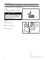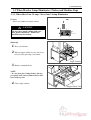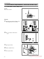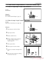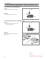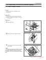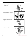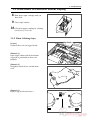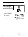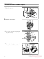
1
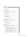
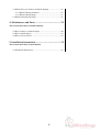
Standard PS-P61
Punch Stapler
Instruction Manual
Provided By
http://www.MyBinding.com
http://www.MyBindingBlog.com
PUNCH STAPLE
PS-P61
Important Information
- This manual is designed to help you to install, operate and maintain Punch Staple PSP61. Read, understand and keep this manual in a safe and convenient place.
- Do not operate PS-P61 until you read and understand the instructions in this manual.
- Horizon International Inc. shall not be liable for incidental consequential damages resulting from : improper or inadequate maintenance by customer; unauthorized modification or
misuse; operation outside of the environmental specifications for the product.
- Horizon International Inc. pursues a policy of continuing improvement in design and
performance of the product. Therefore, the product design and specifications are subject to
change without prior notice and without our legal obligation.
- All rights are reserved. No part of the manual may be photocopied, reproduced or translated to another language without the prior written consent of Horizon International Inc.
UM201013-09
070720/PSP61/09E/DV
I
Safety Precautions
- The signal word WARNING indicates a potentially hazardous situation which, if not
avoided, could result in death or serious injury.
- The signal word CAUTION indicates a potentially hazardous situation which, if not
avoided, may result in damage on machines. It may also be used to alert against unsafe
practices.
- Read and understand all safety instructions with signal word such as WARNING and
CAUTION. If safety instructions are ignored, personal injury may result.
- Horizon International Inc. cannot anticipate every possible situation that might involve
a potential hazard. The instructions in this manual and warning labels on the machine are
therefore not all inclusive.
- All equipment shall be locked out or tagged out to protect against accidental or inadvertent operation when such operation could cause injury to personnel. Do not attempt to
operate any switch, valve, or other energy isolating device where it is locked or tagged out.
- Do not operate the machines when any covers are removed.
- Some of the drawings in this manual show the machine uncovered for explaining the
detail or inside of machine.
II
Contents
Important Information .....................................................................I
Safety Precautions ...........................................................................II
1. Before You Begin ..................................................... 1
This section explain parts and their function of PS-P61.
1-1 Specifications ............................................................................ 2
1-2 Accessories ...............................................................................3
1-3 Accessories (Option) ................................................................. 4
1-4 Consumption Parts ....................................................................5
1-5 Machine Descriptions ...............................................................6
1-5-1 Machine Descriptions ...................................................... 6
1-5-2 Operation Panel Descriptions .......................................... 7
2. How to Operate ........................................................ 9
This section instructs how to set up and operate PS-P61.
2-1 Operation Procedure ................................................................. 10
2-2 To Staple Custom Size Sheets ..................................................14
2-3 Installation of Punch Unit (Option) .......................................... 15
3. Troubleshooting ....................................................... 19
This section shows remedies for simple malfunctions.
3-1 When Monitor Lamp Illuminates / Flashes and Machine Stops ......... 20
3-1-1 When Sheet Jam 1 Lamp Illuminates .............................. 20
3-1-2 When Sheet Jam 2 Lamp / Sheet Jam 3 Lamp Illuminates ....... 21
3-1-3 When Punch Trouble Lamp Flashes ...............................22
3-1-4 When No Staple/Staple Trouble Lamp Illuminates ........23
3-1-5 When No Staple / Staple Trouble Lamp Flashes ............23
3-1-6 When Door Lamp Illuminates ......................................... 24
3-1-7 When Receiving Tray Lamp Illuminates ........................24
III
3-2 When Sheets Are Delivered without Stapling ..........................25
3-2-1 When Collating Continues ..............................................25
3-2-2 When Collating Stops ......................................................27
3-3 When Circuit Breaker Trips ......................................................28
4. Maintenance and Parts ........................................... 29
This section shows how to maintain PS-P61.
4-1 How to Remove Jammed Staples .............................................30
4-2 How to Refill Staples ................................................................32
4-3 How to Clean Sensors ...............................................................34
5. Installation Instructions .......................................... 35
This section shows how to install PS-P61
5-1 Installation Instructions .............................................................35
IV
1. Before You Begin
1. Before You Begin
This section explain parts and their function of PS-P61.
1-1 Specifications ......................................................................................... 2
1-2 Accessories ............................................................................................. 3
1-3 Accessories (Option) .............................................................................. 4
1-4 Consumption Parts ................................................................................ 5
1-5 Machine Descriptions ............................................................................ 6
(1)
1. Before You Begin
1-1 Specifications
Functions
Top Stapling, Angled Corner Stapling, Straight Corner Stapling, Other
Side Corner Stapling, Two Hole Punching (option)
Max. W 300 x L 432 mm
Min. W 182 x L 257 mm
Sheet Size
Top Stapling : A4 / 8.5" x 11"/ 8.5" x 14"
Angled Corner Stapling : A3 / A4 / 11" x 17" / 8.5" x 11"/ 8.5" x 14"
Straight Corner Stapling : A3 / A4 / 11" x 17" / 8.5" x 11"/ 8.5" x 14"
Other Side Corner Stapling : A4 / 8.5" x 11"/ 8.5" x 14"
Two Hole Punching (option) : A4 / 8.5" x 11"/ 8.5" x 14"
Sheet Weight Range
Normal Paper 53 to 127 gsm (Up to 104 gsm on Punching)
Stitch Thickness
Side or Corner Stapling : Max. 10 sheets (Normal Paper 127 gsm)
Optional Punch Capability : Max. 10 sheets (Normal Paper 104 gsm)
Stitch Distance
Staple Distance : 148 mm (A4), 8.14" (8.5" x 14"), 5.13" (11" x 8.5")
Corner Staple Angle : 0 degree or 30 degree selectable
Stapling Wire
No.510 Cartridge Type (5,000 staples/cartridge)
Error Detector / Indicator
Sheet Jam, No Staple, Stapler Error, Cover Open, Sheets Full on Delivery
Tray
Production Speed
Side Stapling : Max. 12 sets / min.
Corner Stapling : Max. 25 sets / min.
Voltage/Frequency
Single Phase 115V, 60 Hz
Single Phase 230V, 50 Hz
Rated Current
230V, 50 Hz : 0.8 A
Heat Out Put
400 kJ (90 kcal)
Machine Dimensions
1,115 (W) x 562 (D) x 580 (H) mm (with Delivery Tray)
(43.9" x 22.2" x 22.9")
Machine Weight
74 kg (163.2 lb)
Options
Punch Unit
The machine design and specifications are subject to change without any notice.
(2)
1. Before You Begin
1-2 Accessories
Sheet Guide
Power Cord (4-007736-00)
1 unit
1 pc
Collator Lock Bolts
2 pcs
Plastic Mounts
2 pcs
Receiving Sheet Guides (M901253-10)
Allen Wrench 3 mm
SB Screws
2 pcs
1 pc
2 pcs
(3)
1. Before You Begin
1-3 Accessories (Option)
Punch Unit (A903222-00)
1 pc
Guide (M041593-11)
Box (M041594-20)
1 pc
Screw
(4)
1 pc
2 pcs
1. Before You Begin
1-4 Consumption Parts
Staple Cartridge (No. 500)
1 pc
(5)
1. Before You Begin
1-5 Machine Descriptions
1-5-1 Machine Descriptions
Punch Unit
This unit punches two holes.
Transport Unit
This unit transports collated
sheets to staple section of
PS-P61.
Staple Unit
This unit staples sheets.
It has two staple angle
positions.
Receiving Tray
Stapled/ Punched sheets
are delivered in this tray.
Operation Panel
Jog Guide Scale
This scale shows positions
of jog guide.
Counter
This counter shows total
number of books made.
(For maintenance)
Bottom cover
Tray for punch chip is housed in this
cover.
(6)
Jog Guide
This guide jogs sheets.
Staple Cabinet
Sheets are jogged, and
stapled/ punched here.
1. Before You Begin
1-5 Machine Descriptions
1-5-2 Operation Panel Descriptions
Monitor Lamp
This lamp flashes when
troubles happen.
Jog Button
This button is used to select jog
time, 1 time or 2 times. Standard
setting is 1.
1
14"
2
8.5"
A4
A4
11"
11"
A3
17"
Jog Guide Knob
This knob is used to adjust jog
guide position. Push and turn it.
Stapling Mode Button
This button is used to select stapling
modes, corner stapling (angled/straight/
other side) or side stapling.
A3
Eject Button
This button is used to eject
sheets staying in machine.
Also, used to reset punch or/
and staple.
Punch Button
This button is used to punch mode,
punch ON or OFF.
(7)
1. Before You Begin
(8)
2. How to Operate
2. How to Operate
This section instructs how to set up and operate PS-P61.
2-1 Operation Procedure ........................................................................... 10
2-2 To Staple Custom Size Sheets ............................................................ 14
2-3 Installation of Punch Unit (Option) ................................................... 15
(9)
2. How to Operate
2-1 Operation Procedure
1. Plug power cord of collator into outlet.
2. Turn on power switch of collator.
3. Pile sheets on collator.
01PSP61A03
NOTE
- Pile sheets on the bottom bin to be used
then pile sheets on the upper bin.
- Pile sheets with their face down.
- Refer to collator operation manual to
operate collator.
P10
P1
- Pile sheets as shown in the right drawing.
B5
A4
B4
A3
01PSP61A05
(10)
2. How to Operate
2-1 Operation Procedure
4. Select the left collating direction with
QC-S10
the collating direction button of the
collator (QC-S10/ QC-S100).
QC-S100
5. Push and turn jog guide knobs and
Jog Guide Knob
position jog guides according to sheet
size.
B5
1
B4
2
NOTE
- Set jog guide at the position you hear click
when knobs are turned for regular size
sheets (A3, B4, A4, B5).
- Refer to "2-2 To Staple Custom Size
Sheets" (page 12).
A4
A4
A3
B4
A3
6. Press punch button and select ON
when punch unit (option) is installed
and used.
NOTE
Top stapling and other side corner stapling
cannot be performed when punch unit (Option) is installed. Refer to "2-3 Installation
of Punch Unit (Option)"( page 13).
7. Select staple mode with stapling mode
button.
NOTE
Top stapling and other side corner stapling
on A3 or custom size sheets cannot be performed.
(11)
2. How to Operate
2-1 Operation Procedure
8. Open staple cabinet.
Staple Cabinet
Jog Guide
9. Check whether sheet guide is positioned
properly with arrow marks of jog guide.
17"
A3
400
B4
B5
20
"
8.5
14" 350
0
300
A4
A4
11"
B5
0
25
B4
"
11
0
30 A3
10. Adjust punch unit to sheet size by pulling and sliding punch position knob on
punching.
17"
A3
400
B4
B5
14" 350
0
20
"
8.5
25
B4
300
A4
A4
11"
B5
0
11"
0
30 A3
B4
NOTE
Punch unit can be set at only B4, A4 and B5
positions.
A4
B5
Punch Position
Knob
11. Close staple cabinet.
12. Set receiving tray and receiving tray
Receiving Tray
guide according to sheet size.
NOTE
Set receiving sheet guide wider than sheet
size to prevent sheets from hitting guides.
(12)
Receiving Tray Guide
2. How to Operate
2-1 Operation Procedure
13. Press check button twice.
Press the check button once to set bins to
feed position and then press the check
button again. One set of sheets will be
collated on the receiving tray. Pressing
the check button is to memorize the sheet
thickness and the number of used bins.
QC-S10
QC-S100
NOTE
Check up delivered sheets.
14. Press start button to start collating.
QC-S10
QC-S100
15. When all of set sheets are finished
QC-S10
collating, collating stops.
NOTE
Press stop button of collator when you want
to stop collating.
Stop Button
QC-S100
16. When your job is completed, turn off
power switch and pull out power cord
from outlet.
(13)
2. How to Operate
2-2 To Staple Custom Size Sheets
This section show how to set up parts to
staple custom size sheets.
NOTE
Only angled and straight corner staplings
can be performed when custom size sheets
are used.
1. Measure sheet size.
01PSP61A14
2. Open Staple cabinet.
Staple Cabinet
Jog Guide
3. Push and turn jog guide knobs to position arrow marks to sheet size.
17"
A3
400
B4
B5
0
20
"
8.5
A4
14" 350
300
A4
0
25
B4
4. Close staple cabinet.
11"
0
30 A3
Jog Guide Knob
5. Select staple angle with stapling mode
button.
NOTE
Only angled and straight corner staplings
can be selected.
6. Now set up is completed. Refer to "2-1
Operation Procedure", 12 to 16 (page 10
and 11).
(14)
11"
B5
2. How to Operate
2-3 Installation of Punch Unit (Option)
This section shows how to install punch unit
(Option) to punch sheets.
WARNING
Turn off power switch and unplug
power cord before installing punch
unit.
NOTE
- B4, A4 and B5 sheets can be punched.
- Top stapling and other side corner stapling
cannot be performed when punch unit is
installed.
01PSP61A26
1. Turn off power switch.
2. Open rear cover.
Rear Cover
3. Install punch unit by inserting punch
position knob into slot of punch position
plate.
Punch Unit
4. Connect connector of punch unit.
5. Close rear cover.
Connector
(15)
2. How to Operate
2-3 Installation of Punch Unit (Option)
6. Open staple cabinet.
Staple Cabinet
7. Set punch unit with punch position knob
according to sheet size.
17"
A3
400
B4
B5
14" 350
0
20
"
8.5
300
A4
A4
11"
B5
0
25
B4
NOTE
- Punch unit can be set only on B4, A4, B5
position.
- Follow the reverse procedure of installation when punch unit is removed.
11"
0
30 A3
B4
A4
B5
Punch Position Knob
8. Remove lower rear cover.
Rear Cover
9. Fix guide with two screws.
Guide
(16)
Screws
2. How to Operate
2-3 Installation of Punch Unit (Option)
10. Place box on guide.
Box
11. Install rear cover with screws.
Rear Cover
(17)
2. How to Operate
(18)
3. Troubleshooting
3. Troubleshooting
This section shows remedies for simple malfunctions.
3-1 When Monitor Lamp Illuminates / Flashes and Machine Stops .... 16
3-2 When Sheets Are Delivered without Stapling .................................. 21
3-3 When Circuit Breaker Trips .............................................................. 24
(19)
3. Troubleshooting
3-1 When Monitor Lamp Illuminates / Flashes and Machine Stops
3-1-1 When Sheet Jam 1 Lamp Illuminates
[Cause]
Sheets are jammed in transport unit or
transport unit is open.
CAUTION
While sheet jam 1 lamp is flashing, do
not open staple cabinet until jammed
sheets are removed. Otherwise, machine may be broken.
[Remedy]
1. Open transport unit.
2. Remove jammed sheets.
3. Close transport unit.
Transport Unit
(20)
3. Troubleshooting
3-1 When Monitor Lamp Illuminates / Flashes and Machine Stops
3-1-2 When Sheet Jam 2 Lamp / Sheet Jam 3 Lamp Illuminates
[Cause]
Sheets are jammed in staple cabinet.
CAUTION
Do not close staple cabinet with support guide unit raised. Otherwise,
machine may be broken.
[Remedy]
1. Press eject button.
2. Pull out staple cabinet in case sheets are
not ejected by pressing eject button.
Staple Cabinet
3. Remove jammed sheets.
NOTE
- In case sheet jam 3 lamp flashes, lift support guide unit, remove jammed sheets and
lower delivery unit.
4. Close staple cabinet.
Support Guide Unit
(21)
3. Troubleshooting
3-1 When Monitor Lamp Illuminates / Flashes and Machine Stops
3-1-3 When Punch Trouble Lamp Flashes
[Cause]
Punch unit is locked.
[Remedy]
1. Turn off power switch of collator , then
turn on again after a few seconds.
01PSP61A22
2. Press eject button. Punch unit is
reset.
3. Open staple cabinet.
4. Remove jammed sheets.
5. Close staple cabinet.
Staple Cabinet
(22)
3. Troubleshooting
3-1 When Monitor Lamp Illuminates / Flashes and Machine Stops
3-1-4 When No Staple/Staple Trouble Lamp Illuminates
[Cause]
Out of staples.
[Remedy]
Refill staples.
See "4-2 How to Refill Staples" (page 32).
3-1-5 When No Staple / Staple Trouble Lamp Flashes
[Cause]
Staple unit is locked because of staple jam.
[Remedy]
1. Turn off power switch of collator.
2. Open staple cabinet.
3. Remove jammed sheets.
4. Remove jammed staples referring to
"4-1 How to Remove Jammed
Staples"(page 30).
5. Close staple cabinet.
Staple Cabinet
6. Turn on power switch of collator.
7. Depress eject button, and staple unit is
reset.
8. Check for proper stapling by collating
several sets (7 to 8 sets).
(23)
3. Troubleshooting
3-1 When Monitor Lamp Illuminates / Flashes and Machine Stops
3-1-6 When Door Lamp Illuminates
[Cause]
Staple cabinet or rear cover is open.
[Remedy]
Close staple cabinet or rear cover.
01PSP61A27(E)
3-1-7 When Receiving Tray Lamp Illuminates
[Cause]
Receiving tray is full, or sheets are not
delivered completely.
[Remedy]
Remove sheets from receiving tray, or
delivery area.
(24)
3. Troubleshooting
3-2 When Sheets Are Delivered without Stapling
3-2-1 When Collating Continues
[Cause]
Staples are not fed to stapling section
of staple unit.
[Remedy 1]
Set unnecessary sheets on bin, and check
for proper stapling by collating several sets
(7 to 8 sets).
[Remedy 2]
1. Open staple unit.
Staple Cabinet
2. Pull up and release staple cartridge.
3. Clean staple feed roller with alcoholic
soaked cloth.
Staple Cartridge
Staple Feed
Roller
NOTE
- If oil stains the staple feed roller, the staple
sheet slips while being delivered, and misstitching occurs. Do not lubricate the stapler
unit.
(25)
3. Troubleshooting
3-2 When Sheets Are Delivered without Stapling
4. Lift the face plate holder and pull up the
face plate to the top.
Face Plate Holder
Face Plate
5. Remove jammed staples, or restore the
sheet staples inside the sheet holder.
Sheet Staple
6. Remove the jammed staples from the
staple unit.
7. Push down the face plate until you hear
a click.
Face Plate
(26)
3. Troubleshooting
3-2 When Sheets Are Delivered without Stapling
8. Push down staple cartridge until you
hear click.
9. Close staple cabinet.
10. Check for proper stapling by collating
several sets (7 to 8 sets).
3-2-2 When Collating Stops
Jog Guide
[Cause]
Collated sheets are not jogged neatly.
17"
A3
400
B4
B5
0
20
"
8.5
[Remedy 1]
Open staple cabinet and check whether
jog guide is positioned to sheets size
properly.
14" 350
300
A4
A4
11"
B5
0
25
B4
"
11
0
30 A3
[Remedy 2]
Straighten curled sheets, and fan them
well.
[Remedy 3]
Depress jog switch and select 2.
Jog Time
01PSP61A32
1
2
B4
A4
A3
01PSP61A33(E)
(27)
3. Troubleshooting
3-3 When Circuit Breaker Trips
CAUTION
In case circuit breaker trips again
immediately after resetting, turn off
power switch, and call for your local
dealer to avoid serious damage to your
PS-P61.
1. Turn off power switch of collator.
2. Check inside of SPF-9 for obvious
01PSP61A34
problems such as jammed sheets. If
there is a problem, remove the cause.
3. Reset circuit breaker a few minutes after
turning off power switch.
- Push two left breakers to reset.
- Push up two right breakers to reset.
Breakers(Left) Breakers(Right)
01PSP61A35
(28)
4. Maintenance and Parts
4. Maintenance and Parts
This section shows how to maintain PS-P61.
4-1 How to Remove Jammed Staples ....................................................... 30
4-2 How to Refill Staples ........................................................................... 32
4-3 How to Clean Sensors ......................................................................... 34
(29)
4. Maintenance and Parts
4-1 How to Remove Jammed Staples
1. Open the staple unit.
Staple Cartridge
Staple Unit
2. Pull up the staple cartridge.
3. Lift the face plate holder and pull up the
Face Plate Holder
face plate to the top.
Face Plate
4. Remove jammed staples, or restore the
sheet staples inside the sheet holder.
(30)
Sheet Staple
4. Maintenance and Parts
4-1 How to Remove Jammed Staples
5. Remove the jammed staples from the
staple unit.
6. Push down the face plate until you hear
a click.
Face Plate
7. Install staple cartridge in staple unit and
push it until you hear a click.
8. Close the staple unit.
(31)
4. Maintenance and Parts
4-2 How to Refill Staples
1. Open the staple unit.
Staple Cartridge
Staple Unit
2. Pull up the staple cartridge.
3. Press the button and pull out the sheet
holder.
Button
Sheet Holder
4. Insert staple refill to the back end
Arrow
of case.
NOTE
- Set staple refill so that the arrow direction
of staple refill matches to that of case.
(32)
Staple
Refill
4. Maintenance and Parts
4-2 How to Refill Staples
5. Lift the sheet holder tab.
Tab
6. Pull out the tab backward with the band.
7. Install staple cartridge in staple unit and
push it until you hear a click.
8. Close the staple unit.
(33)
4. Maintenance and Parts
4-3 How to Clean Sensors
If paper dust collects on sheet jam sensors,
sheet jam lamp will stay illuminated or
sheets are delivered without stapling though
they are jogged neatly.
1. Open staple unit.
2. Clean two sensors with clean cloth.
Staple Unit
B4
14" 350
Sensors
300
A4
11"
B5
3. Close staple unit.
(34)
5. Installation Instructions
5. Installation Instructions
This section shows how to install PS-P61.
5-1 Installation Instructions ...................................................................... 34
(35)
5. Installation Instructions
5-1 Installation Instructions
WARNING
- Place the collator on a flat and steady
area. Otherwise the collator may be
topped.
- When collator is laid on its side or on
PS-P61, more than three persons are
needed.
Collator : QC-S10 weight is 61 kg (135
lb).QC-S100 weight is 69 kg (152 lb).
- Be sure to push the bottom of transport door side of the collator when
moving the collator and the PS-P61.
Do not push the bin side. It may cause
fall over the collator.
1. Lay collator with transport unit door
down.
The Side of Transport Unit Door
2. Install two lock bolts with spanner.
Lock Bolts
(36)
5. Installation Instructions
5-1 Installation Instructions
3. Remove two rubber mounts with allen
wrench and install two plastic mounts at
the same position. The plastic mounts is
fixed with the fix screws of rubber
mounts.
Plastic Mounts
Install plastic mount
inside of hole.
Rubber Mounts
NOTE
Install the operation side of two plastic
mounts into the inside of holes.
Install plastic mount
inside of hole.
4. Install collator on PS-P61 so that plastic
mounts are placed into dents of PS-P61.
Plastic
Mounts
5. Remove two fix plates. (4 fix screws
each.)
Fix Screw
Fix Plates
6. Open rear cover.
Rear Cover
(37)
5. Installation Instructions
5-1 Install Instructions
7. Open staple cabinet.
Staple Cabinet
8. Fix collator and PS-P61 with two fix
screws.
9. Close staple cabinet.
Rear Cover
10. Remove two spacers.
Spacers
11. Remove lock bolt.
Lock Bolts
(38)
5. Installation Instructions
5-1 Install Instructions
12. Remove both side covers of transport
unit. (One fix screw each)
Transport Unit
Side Covers
13. Install transport unit with four fix
Lock
Bolts
screws.
NOTE
Insert cord of transport unit into PS-P61.
Transport
Unit
14. Connect cord of transport unit.
CAUTION
NK cramp
Through the
Throug
the
NK
cord
here
- Connect the cord through
cramp shown to the right. Otherwise, a
jam may occur because the cord is
caught when the stitch unit is drawn
forth or fit in.
NK cramp
Pass the cord
through here
15. Install side cover of transport unit. (One
fix screw each)
16. Close rear cover.
(39)
5. Installation Instructions
5-1 Install Instructions
17. Connect connector cable to collator.
Connector Cable
- Connect the connector cable to collator
QC-P66.
Power Cord
- Remove the left receptacle cover on the
drive side of the collator QC-S10 or QCS100 and then connect the connector
cable to collator.
QC-S10/
QC-S100
18. Plug power cord on collator into outlet
of PS-P61.
(40)