1
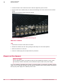
M-2750 Sensor Product Guide
Revision B
McAfee® Network Security Platform
COPYRIGHT
Copyright © 2013 McAfee, Inc. Do not copy without permission.
TRADEMARK ATTRIBUTIONS
McAfee, the McAfee logo, McAfee Active Protection, McAfee DeepSAFE, ePolicy Orchestrator, McAfee ePO, McAfee EMM, Foundscore, Foundstone, Policy
Lab, McAfee QuickClean, Safe Eyes, McAfee SECURE, SecureOS, McAfee Shredder, SiteAdvisor, McAfee Stinger, McAfee Total Protection, TrustedSource,
VirusScan, WaveSecure are trademarks or registered trademarks of McAfee, Inc. or its subsidiaries in the United States and other countries. Other
names and brands may be claimed as the property of others.
Product and feature names and descriptions are subject to change without notice. Please visit mcafee.com for the most current products and features.
LICENSE INFORMATION
License Agreement
NOTICE TO ALL USERS: CAREFULLY READ THE APPROPRIATE LEGAL AGREEMENT CORRESPONDING TO THE LICENSE YOU PURCHASED, WHICH SETS
FORTH THE GENERAL TERMS AND CONDITIONS FOR THE USE OF THE LICENSED SOFTWARE. IF YOU DO NOT KNOW WHICH TYPE OF LICENSE YOU
HAVE ACQUIRED, PLEASE CONSULT THE SALES AND OTHER RELATED LICENSE GRANT OR PURCHASE ORDER DOCUMENTS THAT ACCOMPANY YOUR
SOFTWARE PACKAGING OR THAT YOU HAVE RECEIVED SEPARATELY AS PART OF THE PURCHASE (AS A BOOKLET, A FILE ON THE PRODUCT CD, OR A
FILE AVAILABLE ON THE WEBSITE FROM WHICH YOU DOWNLOADED THE SOFTWARE PACKAGE). IF YOU DO NOT AGREE TO ALL OF THE TERMS SET
FORTH IN THE AGREEMENT, DO NOT INSTALL THE SOFTWARE. IF APPLICABLE, YOU MAY RETURN THE PRODUCT TO MCAFEE OR THE PLACE OF
PURCHASE FOR A FULL REFUND.
2
McAfee® Network Security Platform
M-2750 Sensor Product Guide
Contents
1
2
Preface
5
About this guide . . . . . . . . . . . . . . . . . . . . . . . . . . . . . . . . . .
Audience . . . . . . . . . . . . . . . . . . . . . . . . . . . . . . . . . .
Conventions . . . . . . . . . . . . . . . . . . . . . . . . . . . . . . . . .
What's in this guide . . . . . . . . . . . . . . . . . . . . . . . . . . . . . .
Find product documentation . . . . . . . . . . . . . . . . . . . . . . . . . . . . . .
5
5
5
6
6
Introducing Network Security Sensors
7
About the M-2750 Sensor . . . . . . . . . . . . . . . . . . . . . . . . . . . . . . .
M-2750 physical description . . . . . . . . . . . . . . . . . . . . . . . . . . . . . .
Ports on the Sensor . . . . . . . . . . . . . . . . . . . . . . . . . . . . . .
Front and back panel LEDs . . . . . . . . . . . . . . . . . . . . . . . . . . .
7
7
8
9
Before you install
13
Usage restrictions . . . . . . . . . . . . . . . . . . . . . . . . . . . . . . . . .
Safety measures . . . . . . . . . . . . . . . . . . . . . . . . . . . . . . . . . .
Working with fiber-optic ports . . . . . . . . . . . . . . . . . . . . . . . . . . . . .
Contents of the Sensor box . . . . . . . . . . . . . . . . . . . . . . . . . . . . . .
Unpack the Sensor . . . . . . . . . . . . . . . . . . . . . . . . . . . . . . . . .
3
Setting up the Sensor
17
Setup overview . . . . . . . . . . . . . . . . . . . . . . . . . . . . . . . . . .
Position the Sensor . . . . . . . . . . . . . . . . . . . . . . . . . . . . . . . . .
Install the rails and ears on the chassis and rack . . . . . . . . . . . . . . . . . .
Mount the Sensor on a rack . . . . . . . . . . . . . . . . . . . . . . . . . .
Remove a Sensor from the rack . . . . . . . . . . . . . . . . . . . . . . . . .
Redundant power supply . . . . . . . . . . . . . . . . . . . . . . . . . . . . . . .
Install the power supply . . . . . . . . . . . . . . . . . . . . . . . . . . . .
Remove the power supply . . . . . . . . . . . . . . . . . . . . . . . . . . .
Cable the Sensor . . . . . . . . . . . . . . . . . . . . . . . . . . . . . . . . . .
Small form-factor pluggable modules . . . . . . . . . . . . . . . . . . . . . . . . . .
SFP module . . . . . . . . . . . . . . . . . . . . . . . . . . . . . . . . .
Power on the Sensor . . . . . . . . . . . . . . . . . . . . . . . . . . . . . . . .
Power off the Sensor . . . . . . . . . . . . . . . . . . . . . . . . . . . . . . . .
4
Attaching cables to the Sensor
Cable
Cable
Cable
Cable
Cable
17
17
18
18
19
19
19
20
20
21
21
22
23
25
the Console port . . . . . . . . . . . . . . . . . . . . . . . . . . . . . . .
the Auxiliary port . . . . . . . . . . . . . . . . . . . . . . . . . . . . . . .
the fail-open port . . . . . . . . . . . . . . . . . . . . . . . . . . . . . . .
the Management port . . . . . . . . . . . . . . . . . . . . . . . . . . . . .
the Monitoring ports . . . . . . . . . . . . . . . . . . . . . . . . . . . . . .
How to use peer ports . . . . . . . . . . . . . . . . . . . . . . . . . . . . .
Default Monitoring port speed settings . . . . . . . . . . . . . . . . . . . . . .
Cable types for routers, switches, hubs, and PCs . . . . . . . . . . . . . . . . . .
Cable for in-line . . . . . . . . . . . . . . . . . . . . . . . . . . . . . . . . . .
McAfee® Network Security Platform
13
13
14
14
15
25
26
26
26
27
27
27
28
28
M-2750 Sensor Product Guide
3
Contents
Connect the cables for tap mode . . . . . . . . . . . . . . . . . . . . . . . . . . .
Connect the cables for SPAN or hub mode . . . . . . . . . . . . . . . . . . . . . . . .
Cable the failover interconnection . . . . . . . . . . . . . . . . . . . . . . . . . . .
About the fail-open hardware . . . . . . . . . . . . . . . . . . . . . . . . . . . . .
4
28
29
29
29
5
Troubleshooting the Sensor
31
A
Technical specifications
33
B
Regulatory, compliance, and safety information
35
Index
37
McAfee® Network Security Platform
M-2750 Sensor Product Guide
Preface
This guide provides the information you need to configure, use, and maintain your McAfee product.
Contents
About this guide
Find product documentation
About this guide
This information describes the guide's target audience, the typographical conventions and icons used
in this guide, and how the guide is organized.
Audience
McAfee documentation is carefully researched and written for the target audience.
The information in this guide is intended primarily for:
•
Administrators — People who implement and enforce the company's security program.
•
Users — People who use the computer where the software is running and can access some or all of
its features.
Conventions
This guide uses these typographical conventions and icons.
Book title, term,
emphasis
Title of a book, chapter, or topic; a new term; emphasis.
Bold
Text that is strongly emphasized.
User input, code,
message
Commands and other text that the user types; a code sample; a displayed
message.
Interface text
Words from the product interface like options, menus, buttons, and dialog
boxes.
Hypertext blue
A link to a topic or to an external website.
Note: Additional information, like an alternate method of accessing an
option.
Tip: Suggestions and recommendations.
Important/Caution: Valuable advice to protect your computer system,
software installation, network, business, or data.
Warning: Critical advice to prevent bodily harm when using a hardware
product.
McAfee® Network Security Platform
M-2750 Sensor Product Guide
5
Preface
Find product documentation
What's in this guide
This guide contains information necessary to setup your M-2750 Sensor model. This information
includes guiding you through preconfiguring, cabling, and troubleshooting your Sensor.
Find product documentation
McAfee provides the information you need during each phase of product implementation, from
installation to daily use and troubleshooting. After a product is released, information about the product
is entered into the McAfee online KnowledgeBase.
Task
1
Go to the McAfee Technical Support ServicePortal at http://mysupport.mcafee.com.
2
Under Self Service, access the type of information you need:
To access...
Do this...
User documentation
1 Click Product Documentation.
2 Select a product, then select a version.
3 Select a product document.
KnowledgeBase
• Click Search the KnowledgeBase for answers to your product questions.
• Click Browse the KnowledgeBase for articles listed by product and version.
6
McAfee® Network Security Platform
M-2750 Sensor Product Guide
1
Introducing Network Security Sensors
This section describes the McAfee® Network Security Sensors at a high-level and also describes the
McAfee® M-2750 Network Security Sensor (Sensor) in detail.
Sensors are high-performance, scalable, and flexible content processing appliances built for the
accurate detection and prevention of intrusions, misuse, distributed denial of service (DDoS) attacks,
and network access control(NAC) of hosts. When deployed at key access points, a Sensor provides
real-time traffic monitoring to detect malicious activity, and respond to the malicious activity as
configured by the administrator.
After the Sensor is deployed and communication established, Sensors are configured and managed
using the McAfee Network Security Manager (Manager) server.
The process of configuring a Sensor and establishing communication with the Manager is described in
the later chapters of this guide. The Manager server is described in detail in the McAfee Network
Security Platform Manager Administration Guide.
Contents
About the M-2750 Sensor
M-2750 physical description
About the M-2750 Sensor
The M-2750 Sensor provides effective network access control (NAC) of hosts.
NAC hosts involves regulating access to network resources based on host Operational Status level
(Standard/ DHCP NAC), identity of the user logged into the host (IBAC) or both, and OOB NAC (L2,
L3 ). The Sensor also provides the Hybrid NAC functionality where a host is first subjected to
DHCP-NAC and then Standard NAC at different ports of the same Sensor. For more information on the
NAC functionality and configurations of the Manager, see McAfee® Network Security Platform NAC
Administration Guide.
Throughout this guide, the terms 'Sensor' and 'M-2750' refer to the M-2750 Sensor in general.
M-2750 physical description
The high-port density M-2750 Sensor, designed for high bandwidth links, is equipped with twenty Fast
Ethernet ports (or interfaces). This Sensor can monitor ten 1 Gbps Ethernet segments in full-duplex
mode (tap or in-line), and twenty segments in half-duplex mode (monitoring SPAN ports or hubs). An
M-2750 can monitor upto 600 Mbps of aggregate traffic.
McAfee® Network Security Platform
M-2750 Sensor Product Guide
7
1
Introducing Network Security Sensors
M-2750 physical description
Ports on the Sensor
M-2750 Sensor is a 2RU (2 rack unit) and is equipped with the following components:
Figure 1-1 M-2750 Sensor front panel
Item
Description
1
RJ-45 10/100/1000 Management port (1)
2
RS-232C Console port (1)
3
RS-232C Auxiliary port (1)
4
RJ-11 Fail-Open Control ports (10)
5
SFP One Gigabit Ethernet Monitoring ports (20)
6
External Compact Flash port (1)
7
Front panel LEDs (4)
Figure 1-2 M-2750 Sensor back panel
8
Item
Description
8
Power supply A (included)
9
Power supply B (optional; sold separately)
10
Back panel LEDs (5)
1
One RJ-45 10/100/1000 Management port, which is used for communication with the
Manager server. You can assign an IP address to this port during installation.
2
One RS-232C Console port, which is used to set up and configure the Sensor using the CLI.
3
One RS-232C Auxiliary port, which may be used to dial in remotely to set up and configure the
Sensor.
4
Ten RJ-11 Fail-Open Control ports, designed for use the Optical Fail-Open Bypass kit. The ports
are marked X1, X2, X3, X4, X5, X6, X7, X8, X9, and X10, and are used in conjunction with ports
1A/1B, 2A/2B, 3A/3B, 4A/4B, 5A/5B, 6A/6B, 7A/7B, 8A/8B, 9A/9B, and 10A/10B, respectively.
McAfee® Network Security Platform
M-2750 Sensor Product Guide
Introducing Network Security Sensors
M-2750 physical description
5
1
Twenty small form-factor pluggable (SFP) 1 Gigabit Monitoring ports, which enable you to
monitor ten Ethernet segments In-Line.
If you choose to run in failover mode, port 10A is used to interconnect with a standby M-2750
Sensor.
The gigabit ports of the M-2750 running in in-line mode fail-close, meaning that if the Sensor fails, it
will interrupt/block data flow. Refer to the Gigabit Fail-Open Bypass Kit Guide for more information.
6
One External Compact Flash port. This port is used only for flash recovery purposes. That is,
this port is used in troubleshooting situations where the Sensor's internal flash is corrupted and
you need to reboot the Sensor through the external compact flash. For more information, see the
on-line KnowledgeBase at http://mysupport.mcafee.com/Eservice/. Click Search the KnowledgeBase.
7
Front panel LEDs. The LEDs which indicate the Sensor's general operational status. For more
information, see Front and back panel LEDs.
8
Primary Power Supplies—PWR A (included). Power supply A is included with each Sensor. The
supply uses a standard IEC port (IEC320-C13). McAfee provides a standard; 2m NEMA 5-15P (US)
power cable (3 wire). International customers must procure a country-appropriate power cable.
9
Power Supplies—PWR B (optional, purchased separately). Power supply B is a hot-swappable,
redundant power supply. This power supply also uses a standard IEC320-C13 port, and you can
use the McAfee-provided cable or acquire one that meets your specific needs.
10 Back panel LEDs. The LEDs which indicate the Sensor's fan and power supply operational status.
For more information, see Front and back panel LEDs.
See also
Front and back panel LEDs on page 9
Front and back panel LEDs
Figure 1-3 Front panel LEDs
Figure 1-4 Back panel LEDs
Region in the image LEDs represented here
1
Sys, Temp, Flash, Fan
2
Power A
McAfee® Network Security Platform
M-2750 Sensor Product Guide
9
1
Introducing Network Security Sensors
M-2750 physical description
Region in the image LEDs represented here
3
Back panel fan LEDs
4
Management Port Speed, Management Port Link, Response Port Speed,
Response Port Link
5
Gigabit Ports (SFP) Act, Gigabit Ports (SFP) Link
6
Fail-Open Control Port FO, Fail-Open Control Port Err
7
Bypass LEDs
The front panel LEDs provide status information for the health of the Sensor and the activity on its
ports. The back panel LEDs provide information regarding the Sensor fans and the power supply.
The following tables describe the front and back panel LEDs of M-2750:
LED
Status Description
Sys
Green
Sensor is operating.
Amber Sensor is booting. (It could also indicate a system failure.)
Temp Green
Inlet air temperature measured inside chassis is normal. (Chassis temperature OK.)
Amber Inlet air temperature measured inside chassis is too hot. (Chassis temperature too
hot.)
Flash Green
Fan
Activity on external compact flash.
Off
No activity on external compact flash.
Green
All three fans are operating.
Amber One or more fans have failed.
LED
Status Description
Power A
OK
Green
Power Supply A is functioning.
Amber Power Supply A is not functioning.
~AC
Green
Power Supply in AC mode.
Green
Power Supply B is functioning.
Power B (If present - Not
shown in the picture)
OK
Amber Power Supply B is not functioning.
Green
~AC
Power Supply in AC mode.
If a power supply is not present, both green and amber LEDs are off.
Fan 1
Green
Fan 1 is operating.
Amber Fan 1 is not operating.
Fan 2
Green
Fan 2 is operating.
Amber Fan 2 is not operating.
Fan 3
Green
Fan 3 is operating.
Amber Fan 3 is not operating.
10
McAfee® Network Security Platform
M-2750 Sensor Product Guide
Introducing Network Security Sensors
M-2750 physical description
LED
Status Description
Management Port Speed
Green
1
The port speed is 1000 Mbps.
Amber The port speed is 100 Mbps.
Management Port Link
Response Port Speed
Off
The port speed is 10 Mbps.
Green
The link is connected.
Off
The link is disconnected.
Green
The port speed is 1000 Mbps.
Amber The port speed is 100 Mbps.
Response Port Link
Gigabit Ports (SFP) Act
Gigabit Ports (SFP) Link
Fail-Open Control Port FO
Fail-Open Control Port Err
Off
The port speed is 10 Mbps.
Green
The link is connected.
Off
The link is disconnected.
Amber Data transferring.
Off
No data transferring.
Green
The link is connected.
Off
The link is disconnected.
Green
The Sensor is powering the fail-open kit.
Off
The Sensor is not powering the fail-open kit.
Amber The fail-open control cable is disconnected or the Sensor is
operating in bypass mode.
Off
There is no error.
Byp1, Byp2 Byp3, Byp4
In-line, Fail-open
Green
The Sensor port pair is in-line, receiving normal traffic.
In-line, Fail-close
The Sensor port pair is in-line, receiving normal traffic.
Tap or SPAN
The Sensor port receives normal traffic. Traffic is either
passing through or has been dropped.
Bypass
McAfee® Network Security Platform
OFF
The Sensor port pair is not in-line and traffic is bypassed.
M-2750 Sensor Product Guide
11
1
Introducing Network Security Sensors
M-2750 physical description
12
McAfee® Network Security Platform
M-2750 Sensor Product Guide
2
Before you install
This chapter describes the best practices for deployment of Sensors on your network. Topics include
system requirements, site planning, safety considerations for handling the Sensor, and usage
restrictions that apply to the Sensor model.
Contents
Usage restrictions
Safety measures
Working with fiber-optic ports
Contents of the Sensor box
Unpack the Sensor
Usage restrictions
The following restrictions apply to the use and operation of a Sensor:
•
You may not remove the outer shell of the Sensor. Doing so will invalidate your warranty.
•
The Sensor appliance is not a general purpose workstation.
•
McAfee prohibits the use of the Sensor appliance for anything other than operating McAfee®
Network Security Platform (formerly McAfee® IntruShield®).
•
McAfee prohibits the modification or installation of any hardware or software in the Sensor
appliance that is not part of the normal operation of McAfee Network Security Platform.
Safety measures
Please read the following warnings before you install the product. These safety measures apply to all
Sensor models unless otherwise specified.
Failure to observe these safety warnings could result in serious physical injury.
Warnings:
•
Read the installation instructions before you connect the system to its power source.
•
To remove all power from the Sensor, unplug all power cords, including the redundant power cord.
•
Only trained and qualified personnel should be allowed to install, replace, or service this
equipment.
•
Before working on an equipment that is connected to power lines, remove jewelry (including rings,
necklaces, and watches). Metal objects will heat up when connected to power and ground, and can
cause serious burns or weld the metal object to the terminals.
McAfee® Network Security Platform
M-2750 Sensor Product Guide
13
2
Before you install
Working with fiber-optic ports
•
This equipment is intended to be grounded. Ensure that the host is connected to earth ground
during normal use.
•
Do not remove the outer shell of the Sensor. Doing so will invalidate your warranty.
•
Do not operate the system unless all cards, faceplates, front covers, and rear covers are in place.
Blank faceplates and cover panels prevent exposure to hazardous voltages and currents inside the
chassis, contain electromagnetic interference (EMI) that might disrupt other equipment, and direct
the flow of cooling air through the chassis.
•
To avoid electric shock, do not connect safety extra-low voltage (SELV) circuits to
telephone-network voltage (TNV) circuits. LAN ports contain SELV circuits, and WAN ports contain
TNV circuits. Some LAN and WAN ports both use RJ-45 connectors. Use caution when connecting
cables.
•
This equipment has been tested and found to comply with the limits for a Class A digital device,
pursuant to Part 15 of the FCC Rules. These limits are designed to provide reasonable protection
against harmful interference when the equipment is operated in a commercial environment. This
equipment generates, uses, and can radiate radio frequency energy and, if not installed and used
in accordance with the instruction manual, may cause harmful interference to radio
communications.
•
Operation of this equipment in a residential area is likely to cause harmful interference in which
case users will be required to correct the interference at their own expense.
Working with fiber-optic ports
The Sensor uses fiber-optic connectors for its Monitoring ports. The connector type is a small
form-factor pluggable (SFP) fiber-optic connector that is LC-duplex compatible.
Note the following:
•
Fiber-optic SFP ports are considered Class 1 laser or Class 1 LED ports.
To avoid exposure to radiation, do not stare into the aperture of a fiber-optic port. Invisible radiation
might be emitted from the aperture of the port when no fiber cable is connected.
•
Only FDA registered, EN 60825-1 and IEC 60825-1 certified Class 1 SFP laser transceivers are
acceptable for use with the Sensor.
Contents of the Sensor box
The following accessories are shipped in the Sensor crate:
14
•
One Sensor.
•
One power supply.
•
Power cords. McAfee provides standard and international power cables.
•
One set of rack mounting rails.
•
One set of rack mounting ears.
•
One printed M-2750 Slide Rail Assembly Procedure.
•
One printed M-2750 Quick Start Guide.
•
Release Notes.
McAfee® Network Security Platform
M-2750 Sensor Product Guide
Before you install
Unpack the Sensor
2
Unpack the Sensor
Task
1
Place the Sensor box as close to the installation site as possible.
2
Position the box with the text upright.
3
Open the top flaps of the box.
4
Remove the accessory box within the Sensor box.
5
Verify you have received all parts.
These parts are listed on the packing list and in Contents of the Sensor box.
6
Remove the Slide Rail Kit.
7
Pull out the packing material surrounding the Sensor.
8
Remove the Sensor from the anti-static bag.
9
Save the box and packing materials for later use in case you need to move or ship the Sensor.
If any of the contents from the preceding list are missing or damaged, contact McAfee support.
McAfee® Network Security Platform
M-2750 Sensor Product Guide
15
2
Before you install
Unpack the Sensor
16
McAfee® Network Security Platform
M-2750 Sensor Product Guide
3
Setting up the Sensor
This chapter describes the process of setting up a Sensor to prepare it for configuration.
Contents
Setup overview
Position the Sensor
Redundant power supply
Cable the Sensor
Small form-factor pluggable modules
Power on the Sensor
Power off the Sensor
Setup overview
Setting up a Sensor involves the following steps:
Task
1
Positioning the Sensor.
2
Installing interface modules (SFP).
3
Attaching power, network, and monitoring cables.
4
Powering on the Sensor.
5
Configuring the Sensor after you have set up and powered on the Sensor.
See also
Position the Sensor on page 17
Attaching cables to the Sensor on page 3
Position the Sensor
Place the Sensor in a physically secure location, close to the switches or routers it will be monitoring.
Ideally, the Sensor should be located within a standard communications rack. Each M-2750 is a 2RU (2
rack unit). To mount the Sensor on a rack, you will attach two mounting ears and rails to the Sensor
as described in the subsequent sections.
McAfee® Network Security Platform
M-2750 Sensor Product Guide
17
3
Setting up the Sensor
Position the Sensor
Install the rails and ears on the chassis and rack
Before you begin
Before you install the rails and ears on the chassis, make sure that power is OFF. Remove
the power cable and all network interface cables from the Sensor.
Each rack-mounting rail and ear has holes that match up with holes in the chassis. You will need a
screwdriver to secure the slotted panhead screws.
Task
1
Verify that you have all the parts you will need: two three-in-one rails, two chassis ears, and
fourteen slotted panhead screws.
Each rail includes a rail that mount to the rack, a rail that slides into the mounted rail, and a rail
that is attached to the chassis.
2
Disassemble the slide rail by pulling the inner rail out and pushing the side latch in to separate.
3
Attach the inner rail to the chassis by fastening it with the screws provided.
4
Attach the ear to each side of the chassis.
5
Mount the L-shape and external rail to your rack frame.
The adjustable end of the L-shape rail is intended for placement at the back of your rack. Adjust
the rail as needed for length. You are now ready to mount the Sensor in the rack.
Mount the Sensor on a rack
McAfee recommends rack-mounting your Sensors. The rack-mounting hardware included with the
Sensors is suitable for most 19-inch equipment racks and telco-type racks. For maintenance purposes,
you should have access to the front and rear of the Sensor.
Before you mount the Sensor on the rack, make sure that power is OFF. Remove the power cable and all
network interface cables from the Sensor.
Because of the weight of the appliance, McAfee recommends that two people place the chassis into the
rail cabinet.
Insert the chassis into the rail cabinet and complete the rack-mounting of the Sensor by securing the
rack mount ears to two posts or mounting strips in the rack. The ears secure the Sensor to two rack
posts. Be sure to fasten the ears securely to the rack.
You can also mid-mount the Sensor (optional). For details, refer to the corresponding Sensor McAfee
Network Security Platform Quick Start Guide.
18
McAfee® Network Security Platform
M-2750 Sensor Product Guide
Setting up the Sensor
Redundant power supply
3
Remove a Sensor from the rack
Because of the weight of the appliance, McAfee recommends that two people remove the chassis from
the rail cabinet. When removing the chassis from the rack, pull chassis forward until you hear the
innermost rails snap in place. On each side of the rails, press in the release button as pictured below
and continue pulling the chassis.
Figure 3-1 Rail release latch for the Sensor
Redundant power supply
A basic configuration of the Sensor includes one hot swappable supply. You may install a second
hot-swappable power supply (purchased separately from McAfee) for redundancy. Each of these
modules has one handle for insertion or extraction from the unit as well as a release latch.
Figure 3-2 Inserting the power supply for the Sensor
Install the power supply
Task
1
Unpack the power supply from its shipping carton.
2
Remove the faceplate panel covering the power supply slot.
The faceplate panel should remain in place unless a power supply is in the power supply slot. Do not
operate the Sensor without the faceplate panel in place.
McAfee® Network Security Platform
M-2750 Sensor Product Guide
19
3
Setting up the Sensor
Cable the Sensor
3
Place the power supply in the slot with the cable outlet facing front and on the left side of the
faceplate.
Figure 3-3 Power supply units of the Sensor
4
Slide in the power supply until it makes contact with the backplane, then push firmly to mate the
connectors solidly with the backplane.
For true redundant operation with the optional redundant power supply, McAfee recommends that
you plug each supply into a different power circuit. For optimal protection, use uninterruptable
power sources.
Remove the power supply
Note that the power supplies are hot-swappable. To avoid data interruption, do not power off both
power supplies on an in-line Sensor, else the Sensor shuts down and all data traffic stops. Power off
only the power supply you are replacing.
Task
1
Unplug the power cable from its power source and remove the power cable from the power supply.
2
Put on an antistatic wrist or ankle strap.
3
Attach the strap to a bare metal surface of the chassis.
4
Push the release latch inward toward the handle.
5
Squeeze the handle of the power supply and pull it out.
6
Use faceplate panels to protect unused slots from dust and reduce electromagnetic radiation.
7
Replace the mounting bracket.
To remove all power from the Sensor, unplug all power cords.
Cable the Sensor
Follow the steps outlined in Attaching Cables to the Sensor to connect cables to the monitoring,
response, console, and management ports on your Sensor.
See also
Attaching cables to the Sensor on page 3
20
McAfee® Network Security Platform
M-2750 Sensor Product Guide
Setting up the Sensor
Small form-factor pluggable modules
3
Small form-factor pluggable modules
The Sensor uses two types of small form-factor pluggable modules as shown in the following table.
Type
Performance
SFP
10/100/1000 Mbps (copper)
1 Gbps (fiber optic)
Each module is a hot-swappable input/output device that plugs into an LC-type Gigabit Ethernet port,
linking the module port with a copper or fiber-optic network. SFP optical interfaces are less than half
the size of GBIC interfaces.
To ensure compatibility, McAfee supports only those SFP modules purchased through McAfee or from a
McAfee-approved vendor. For a list of approved vendors, see the on-line KnowledgeBase at http://
mysupport.mcafee.com/Eservice/. Click Search the KnowledgeBase.
These installation instructions provide information for installing an SFP module that uses a bail-clasp
for securing the module in place in the Sensor. Your module may be slightly different. Check the
module manufacturer's installation instructions for more details.
For ease of installation, insert the module in the Sensor while it is powered down and before placing it
on a rack.
To prevent eye damage, do not stare into open laser apertures.
SFP module
The SFP module is a hot-swappable, protocol-independent, compact, optical receiver, which allows for
greater port density than the standard GBIC. This module operates at varying speeds for up to 1
Gigabit per second on Gigabit Ethernet. The SFP module operates in single mode and multimode.
Additionally, this module transmits on an 850-nanometer wavelength on short reach (SR) and
1310-nanometer wavelength on long reach (LR).
Figure 3-4 SFP module for the Sensor
Install a module
This section provides the steps to install an SFP module with a bail clasp.
Task
1
Remove the module from its protective packaging.
2
Ensure the module is the correct model for your network.
McAfee® Network Security Platform
M-2750 Sensor Product Guide
21
3
Setting up the Sensor
Power on the Sensor
3
Locate the label on the module and ensure that the alignment groove is down.
4
Grip the sides of the module with your thumb and forefinger and insert module into the module
socket.
Modules are keyed to prevent incorrect insertion.
Figure 3-5 SFP module in the Sensor Monitoring port
Remove a module
Task
1
Disconnect the network cable from the module.
2
Release the module from the slot by pulling the bail-clasp out of its locked position.
3
Slide the module out of the slot.
4
Insert the module plug into the optical bore for protection.
Power on the Sensor
Before you begin
Do not attempt to power on the Sensor until you have installed the Sensor in a rack, made
all necessary network connections, and connected the power cable to the power supply.
If you are installing a redundant power supply, you should install it as described in Installing a power
supply. For true redundant operation with the optional redundant power supply, McAfee recommends
that you plug each supply into a different power circuit.
22
McAfee® Network Security Platform
M-2750 Sensor Product Guide
Setting up the Sensor
Power off the Sensor
3
Task
1
Connect the power cable to the Sensor power supply.
2
Connect the power cable to a power source.
The Sensor has no power switch. It powers on as soon as one of its power cable is connected to a
power source.
Power off the Sensor
McAfee recommends that you use the shutdown CLI command to halt the Sensor before powering it
down. For more information on CLI commands, see McAfee Network Security Platform CLI Guide.
McAfee® Network Security Platform
M-2750 Sensor Product Guide
23
3
Setting up the Sensor
Power off the Sensor
24
McAfee® Network Security Platform
M-2750 Sensor Product Guide
4
Attaching cables to the Sensor
Follow the steps outlined in this chapter to connect cables to the various ports on your Sensor.
Contents
Cable the Console port
Cable the Auxiliary port
Cable the fail-open port
Cable the Management port
Cable the Monitoring ports
Cable for in-line
Connect the cables for tap mode
Connect the cables for SPAN or hub mode
Cable the failover interconnection
About the fail-open hardware
Cable the Console port
The Console port on the Sensor is used for setup and configuration of the Sensor.
Task
1
For console connections, plug the DB9 Console cable supplied by McAfee into the Console port on
the Sensor.
This port is labeled as Console on the Sensor front panel.
2
Connect the other end of the Console port cable directly to a COM port of the PC or terminal server
you will use to configure the Sensor, for example, a PC running correctly configured Windows
HyperTerminal software.
You must connect directly to the console for initial configuration.
Required settings for HyperTerminal are:
3
Name
Setting
Baud rate
38400
Number of bits
8
Parity
None
Stop bits
1
Flow Control
None
Power on the Sensor.
McAfee® Network Security Platform
M-2750 Sensor Product Guide
25
4
Attaching cables to the Sensor
Cable the Auxiliary port
Cable the Auxiliary port
The Auxiliary port is used for modem access to the Sensor for setup and configuration.
You cannot use a modem the first time you configure a Sensor.
Task
1
For modem connections, plug a straight-through modem cable into the Auxiliary port on the
Sensor.
This port is labeled as Aux on the Sensor front panel.
2
Connect a modem to the Aux port.
3
Connect a telephone line to the modem.
Required settings for the Aux port are:
Name
Setting
Baud rate
38400
Number of bits
8
Parity
None
Stop bits
1
Flow Control
None
Cable the fail-open port
Fail-open functionality for the GE Monitoring ports is accomplished using the standard Gigabit
Fail-open Bypass Kit, sold separately. McAfee recommends deploying active fail-open kits for
protection of mission critical networks. Both copper and optical versions are available. For more
information, see the documentation that accompanies the Kit.
Cable the Management port
The Management port is used for communication with the Manager server.
Task
1
Plug a Cat-5e Ethernet cable into the Management port.
This port is labeled as Mgmt on the front panel of the Sensor.
2
Connect the other end of the cable to the network device, such as a hub, a switch, or a router that
in turn connects to the Manager server.
To isolate and protect your management traffic, McAfee strongly recommends using a separate,
dedicated management subnet to interconnect the Sensors and the Manager.
26
McAfee® Network Security Platform
M-2750 Sensor Product Guide
4
Attaching cables to the Sensor
Cable the Monitoring ports
Cable the Monitoring ports
Connect to the network devices you will be monitoring through the Sensor Monitoring ports. You can
deploy Sensors in the following operating modes:
•
In-line mode (fail-closed)
•
SPAN or Hub mode
•
In-line mode (fail-open)
•
Failover
•
External tap mode
How to use peer ports
All full-duplex Sensor deployment modes require the use of two peer monitoring ports on the Sensor.
On the Sensors, the numbered ports are wired in pairs to accommodate the traffic.
The following SFP Gigabit Ethernet ports are coupled and must be used together:
Port Pairs
Transceiver Type
1A and 1B
SFP
2A and 2B
SFP
3A and 3B
SFP
4A and 4B
SFP
5A and 5B
SFP
6A and 6B
SFP
7A and 7B
SFP
8A and 8B
SFP
9A and 9B
SFP
10A and 10B
SFP
You cannot configure, for example, 1A and 2A to work together as a pair.
Figure 4-1 Using peer ports
Default Monitoring port speed settings
Be sure that the switch/router ports connected to the Sensor Monitoring ports match the Sensor
configuration.
Table 4-1 Default Monitoring port speed settings
Monitoring Ports
Operating Mode
Speed/Duplex Setting
SFP ports for copper
In-line fail-close (port pair)
Auto-negotiation is on.
SFP ports for fiber-optic
In-line fail-close (port pair)
Auto-negotiation is on.
McAfee® Network Security Platform
M-2750 Sensor Product Guide
27
4
Attaching cables to the Sensor
Cable for in-line
Cable types for routers, switches, hubs, and PCs
This section describes the types of cables that you require to connect the Sensor to other network
devices:
•
Use a crossover Ethernet RJ-45 cable to connect a router port to the 10/100/1000 copper SFP
Monitoring ports.
•
Use a straight-through Ethernet RJ-45 cable to connect a switch/hub port to 10/100/1000 copper
SFP Monitoring ports.
•
Use a crossover Ethernet RJ-45 cable to connect a router port to PC to the Sensor Management
port.
You should also use a crossover Ethernet RJ-45 cable to connect a PC to the Sensor monitoring port.
Cable for in-line
The Gigabit Ethernet ports fail-close, meaning they stop the flow of traffic if the Sensor fails. To allow
traffic to flow uninterrupted, you must use special hardware and cable the Sensor for fail-open
functionality. For instructions, see the section later in this chapter.
This section provides the steps to connect the Sensor's Gigabit Ethernet ports so they fail-close.
Task
1
Plug the cable appropriate for use with your Gigabit Ethernet into one of the Monitoring ports, for
example, 1A.
2
Plug another cable into the peer of the port used in Step 1.
3
Connect the other end of each cable to the network devices that you want to monitor.
For example, if you plan to monitor traffic between a switch and a router, connect the cable
connected to 1A to the switch and the one connected to 1B to the router.
See also
Cable types for routers, switches, hubs, and PCs on page 28
How to use peer ports on page 27
Connect the cables for tap mode
To deploy the Sensor in tap mode, you must use a Sensor's Gigabit Ethernet Monitoring port pair with
a third-party external tap.
For a list of McAfee-approved third party vendors, see the KnowledgeBase at http://
mysupport.mcafee.com/Eservice/. Click the link Search the KnowledgeBase and locate the relevant
KnowledgeBase article.
Task
28
1
Plug the cable appropriate for use with your Gigabit Ethernet into one of the Monitoring ports, for
example, 1A.
2
Plug another cable into the peer of the port used in Step 1.
McAfee® Network Security Platform
M-2750 Sensor Product Guide
Attaching cables to the Sensor
Connect the cables for SPAN or hub mode
3
Connect the other end of each cable to the tap.
4
Connect the network devices that you want to monitor to the tap.
4
Connect the cables for SPAN or hub mode
For the Sensor, monitoring in SPAN or hub mode occurs in in-line fail-open mode. When you monitor in
SPAN or hub mode, you use only single ports.
To connect an Sensor to a SPAN port or hub, plug an LC fiber-optic or 45 cable into one of the modules
and connect the other end of the cable to the SPAN port or the hub.
Cable the failover interconnection
Failover requires connecting two identical M-2750 Sensors (same model, same software) using an
interconnection cable or cables. Gigabit ports 10A is the failover interconnection port on the M-2750
Sensor. A failover cable is the only additional hardware required to support failover communication
between two M-2750 Sensors.
Task
1
Plug the cable appropriate for use with your SFP module into port 10A of the active Sensor.
2
Connect the other end of the cable to port 10A of the standby Sensor.
Figure 4-2 M-2750 failover pair
About the fail-open hardware
The standard Gigabit Fail-Open Kit (sold separately) minimizes the potential risks of in-line Sensor
failure on critical network links. Both copper and optical versions of the Kit are available for 1 Gigabit
ports.
McAfee® Network Security Platform
M-2750 Sensor Product Guide
29
4
Attaching cables to the Sensor
About the fail-open hardware
The Monitoring ports on M-2750 fail-close; thus, if the Sensor is deployed in-line, a hardware failure
results in network downtime. Fail-open operation for the Monitoring ports requires the use of the
optional external Bypass Switch provided in the Kit.
With the Bypass Switch in place, normal Sensor operation supplies power to the switch through a
control cable. While the Sensor is operating, the switch is "on" and routes all traffic directly through
the Sensor. When the Sensor fails, the switch automatically shifts to a bypass state: in-line traffic
continues to flow through the network link, but is no longer routed through the Sensor. Once the
Sensor resumes normal operation, the switch returns to the "on" state, once again enabling in-line
monitoring.
Note that Sensor outage breaks the link connecting the devices on either side of the Sensor for a brief
moment and requires the renegotiation of the network link between the two peer devices connected to
the Sensor. Depending on the network equipment, this disruption introduced by the renegotiation of the
link layer between the two peer devices may range from a couple of seconds to more than a minute
with certain vendors' devices.
A very brief link disruption may also occur while the links between the Sensor and each of the peer
devices are renegotiated to place the Sensor back in in-line mode. This outage, again, varies depending
on the device, and can range from a few seconds to more than a minute.
Installation and troubleshooting instructions for the Kit can be found in the Guide that accompanies
the kit. For example, for more information on the Optical kit, see the standard Gigabit Optical
Fail-Open Bypass Kit Guide.
30
McAfee® Network Security Platform
M-2750 Sensor Product Guide
5
Troubleshooting the Sensor
This section provides the solution to some of the common installation problems.
Problem
Possible Cause
Solution
LED is off.
The control cable has been
disconnected.
Check the control cable and ensure it is
properly connected to both the Sensor and
the Bypass Switch.
LED is off.
The Sensor is powered off.
Restore Sensor power.
LED is off.
The Sensor port cable is
disconnected.
Check the Sensor cable connections.
Sensor is operational, but Network device cables have Check the cables and ensure they are
is not monitoring traffic.
been disconnected.
properly connected to both the network
devices and the Bypass Switch.
Sensor is operational, but The Sensor ports have not
is not monitoring traffic.
been enabled in the
Manager.
The Sensor will not monitor traffic on the
ports unless the ports are enabled in the
Manager. Ports are disabled in a Sensor
failure; they must be re-enabled for Sensor
monitoring to resume.
Network or link
problems.
Improper cabling or port
configuration.
Ensure that the transmit and receive cables
are properly connected to the Bypass
Switch.
Runts or giants errors on
switch and routers.
Improper cabling or port
configuration.
Ensure that the transmit and receive cables
are properly connected to the Bypass
Switch.
The system fault "Switch
absent" appears in the
Manager Operational
Status window.
The control cable has been
disconnected.
Check the control cable and ensure it is
properly connected to both the Sensor and
the Bypass Switch.
McAfee® Network Security Platform
M-2750 Sensor Product Guide
31
5
Troubleshooting the Sensor
32
McAfee® Network Security Platform
M-2750 Sensor Product Guide
A
Technical specifications
The following table lists the specifications for each M-2750 Sensor.
Sensor Specifics
Description
Dimensions
Without mounting ears/rails/cable management:
• width: 15.88 in. (40.34 cm)
• height: 3.38 in. (8.59 cm)
• depth: 24.50 in. (62.23 cm)
Dimensions do not include cables or power cords.
Weight
40 lbs (18.14 kg)
Voltage Range
100-240V AC
Frequency
50/60Hz
Vibration, operating
Sinusoidal: 3 to 500 Hz @ 0.15 gpk
Random: 2.5 to 200 Hz @ 0.33 g
Vibration, non-operating
Sinusoidal: 10 to 500 Hz @ 0.8 gpk
Random: 2.5 to 200 Hz @ 1.05 g
Power requirements
450W
Ambient Temperature Range
(Non-condensing)
Operating
0C(32F) to 40C(104F)
Non-operating
-40C(-40F) to 70C(158F)
Relative Humidity (Non-condensing)
Operating
5%-90% non-condensing
Non-operating
5% to 95% non-condensing
System Heat Dissipation
AC (max): 535W, 1825 BTU/hr
Airflow
200 lfm (1 m/s)
Altitude
Sea level to 10000 ft (3048 m)
McAfee® Network Security Platform
M-2750 Sensor Product Guide
33
A
Technical specifications
34
McAfee® Network Security Platform
M-2750 Sensor Product Guide
B
Regulatory, compliance, and safety
information
The Sensor meets the following standards:
Sensor regulatory, safety, and compliance
Regulatory:
Products with the CE Marking are compliant with the 89/336/EEC and
73/23/EEC directives, which include the safety and EMC standards listed.
Safety certification:
EN 55024: 1998 + A1:2001 + A2: 2003 - Immunity:
• EN-61000-4-2: ESD Immunity
• EN-61000-4-3: Radiated Immunity
• EN-61000-4-4 EFT/B Immunity
• EN-61000-4-5: Surge Protection
• EN-61000-4-6: Conducted Immunity
EN-61000-4-11: Voltage Interruption/Dips (N/A for DC)
CISPR/KN22 :
• KN-61000-4-2: ESD Immunity
• KN-61000-4-3: Radiated Immunity
• KN-61000-4-4 EFT/B Immunity
• KN-61000-4-5: Surge Protection
• KN-61000-4-6: Conducted Immunity
• KN-61000-4-11: Voltage Interruption/Dips (N/A for DC)
Electromagnetic
compliance
(emissions):
FCC Part 15 Class A/Industry Canada ICES-003 Issue 4, February 7, 2004 Class
A
VCCI V-1/93.11, V-2/97.04, V-4/97 Class A
AS/NZS CISPR22: 2004 Class A
CNS 13438: May 1997
SS IEC CISPR22: 1993, Singapore IDA Class A
EN 55024: 1998 + A1:2001 + A2: 2003 - Emissions:
• Radiated Emissions
• Conducted Emissions
• EN 61000-3-2: 2000 Harmonic Current Emissions
• EN 61000-3-3: 1995 + A1: 2001 Voltage Fluctuation/Flicker
CISPR/KN22:
McAfee® Network Security Platform
M-2750 Sensor Product Guide
35
B
Regulatory, compliance, and safety information
Sensor regulatory, safety, and compliance
• Radiated Emissions
• Conducted Emissions
36
McAfee® Network Security Platform
M-2750 Sensor Product Guide
Index
A
M
about this guide 5
auxiliary port 26
management port 26
McAfee ServicePortal, accessing 6
C
P
cabling a failover pair 29, 33
cabling for monitoring ports 27
Cabling for SPAN 29
Cabling for TAP mode 28
chasis 19, 22
conventions and icons used in this guide 5
peer ports 27, 28
D
documentation
audience for this guide 5
product-specific, finding 6
typographical conventions and icons 5
R
rack unit 17
S
Safety 35
Sensor front panel 8, 13, 25
ServicePortal, finding product documentation 6
SFP module 21–23, 25
Slide Rail Kit 15, 17
T
F
fail open port 26
Fibre Optic ports 14
Technical Support, finding product information 6
three-in-one rails 18
G
Gigabit Fail-Open Kit 29, 31
H
hot swappable power supply 19, 20
McAfee® Network Security Platform
M-2750 Sensor Product Guide
37
700-3593B00