1
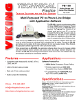
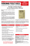
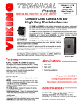
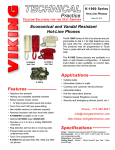
TECHNICAL
Practice
Practice
TELECOM SOLUTIONS
FOR THE
PB-100
Polling Bridge and
Phone Line Interface
2 1 S T C E N T U RY
August 14, 2013
Multi-Purposed PC to Phone Line Bridge
with Application Software
The PB-100 is used to provide status polling
of Viking 1600A Series Emergency Phones
or remote programming of AES-2000 Entry
Systems. The PB-100 can connect to an
unused serial port on your PC or use the
included RS-232 to USB converter cable to
connected to a USB port. A CD is provided
with these two applications along with software for programming other Viking products.
When used to poll 1600A Series Emergency Phones, the application software allows the user
to set up a list of phones to call along with a scheduled time for calling. Through the PB-100,
each phone can be called, its ID code verified and it’s mic and speaker tested. When finished,
the application software logs the time of the call and the results.
When programming an AES-2000, the application software allows the user to manage multiple
units with resident’s phone numbers and access codes. By using a standard telephone connected to the PB-100, the recording of each tenant’s name can be done. The software also supports delayed uploading the downloaded statistics.
Features
Applications
• Compatible with Windows XP, Vista and Win7
Software Provided For:
• USB to RS-232 cable provided
• Audio out jack for monitoring
• 1600A Series Emergency Phone Polling
• Remote programming of AES-2000
Accessible Entry System (DOD# 202)
• PC programming of K-2000-DVA Multi
Input Voice Dialer (DOD# 303)
Specifications
Phone...715.386.8861
[email protected]
h t t p : / / w w w. v i k i n g e l e c t r o n i c s . c o m
Power: 120V AC/12V DC 500mA, UL listed adapter provided
Dimensions: 127mm x 127mm x 25mm (5" x 5" x 1.5")
Weight: 1.36 kg (3 lbs.)
Environmental: 0°C to 32°C (32°F to 90°F) with 5% to 95% noncondensing humidity
P.C. Interface: 9-pin RS-232 or USB port (cable included)
Software/Hardware Requirements:
• IBM Compatible personal computer with an available serial port
CD drive, and Windows compatible sound card
• Windows: 95 or 98 (with OLE32 updates), NT 4.0 (service
pack 6 or higher ), 2000 (service pack 2 or higher), or XP
• 5MB of hard drive space
• 8MB of free physical RAM
Wa r r a n t y
IF YOU HAVE A PROBLEM WITH A VIKING PRODUCT, PLEASE CONTACT: VIKING TECHNICAL SUPPORT AT (715) 386-8666
Our Technical Support Department is available for assistance Monday 8am - 4pm and Tuesday through Friday 8am - 5pm central time. So that we can give you better service, before you call please:
1. Know the model number, the serial number and what software version you have (see serial label).
2. Have your Technical Practice in front of you.
3. It is best if you are on site.
RETURNING PRODUCT FOR REPAIR
RETURNING PRODUCT FOR EXCHANGE
The following procedure is for equipment that needs repair:
1. Customer must contact Viking's Technical Support Department at 715-386-8666 to obtain a Return Authorization (RA)
number. The customer MUST have a complete description of the problem, with all pertinent information regarding the
defect, such as options set, conditions, symptoms, methods to duplicate problem, frequency of failure, etc.
2. Packing: Return equipment in original box or in proper packing so that damage will not occur while in transit. Static
sensitive equipment such as a circuit board should be in an anti-static bag, sandwiched between foam and individually boxed. All equipment should be wrapped to avoid packing material lodging in or sticking to the equipment. Include
ALL parts of the equipment. C.O.D. or freight collect shipments cannot be accepted. Ship cartons prepaid to:
Viking Electronics, 1531 Industrial Street, Hudson, WI 54016
3. Return shipping address: Be sure to include your return shipping address inside the box. We cannot ship to a PO Box.
4. RA number on carton: In large printing, write the R.A. number on the outside of each carton being returned.
The following procedure is for equipment that has failed out-of-box (within 10 days of purchase):
1. Customer must contact Viking’s Technical Support at 715-386-8666 to determine possible causes for the problem. The
customer MUST be able to step through recommended tests for diagnosis.
2. If the Technical Support Product Specialist determines that the equipment is defective based on the customer's input
and troubleshooting, a Return Authorization (R.A.) number will be issued. This number is valid for fourteen (14)
calendar days from the date of issue.
3. After obtaining the R.A. number, return the approved equipment to your distributor, referencing the R.A. number. Your
distributor will then replace the product over the counter at no charge. The distributor will then return the product to
Viking using the same R.A. number.
4. The distributor will NOT exchange this product without first obtaining the R.A. number from you. If you haven't
followed the steps listed in 1, 2 and 3, be aware that you will have to pay a restocking charge.
LIMITED WARRANTY
Viking warrants its products to be free from defects in the workmanship or materials, under normal use and service, for a period of one year from the date of purchase from any authorized Viking distributor or 18 months from the date manufactured, which ever is greater. If at any time during the warranty period, the product is deemed defective or malfunctions, return the product to Viking Electronics, Inc., 1531 Industrial Street, Hudson, WI., 54016. Customer must contact Viking's
Technical Support Department at 715-386-8666 to obtain a Return Authorization (R.A.) number.
This warranty does not cover any damage to the product due to lightning, over voltage, under voltage, accident, misuse, abuse, negligence or any damage caused by use of the product by the purchaser or others. This warranty does not cover
non-EWP products that have been exposed to wet or corrosive environments.
NO OTHER WARRANTIES. VIKING MAKES NO WARRANTIES RELATING TO ITS PRODUCTS OTHER THAN AS DESCRIBED ABOVE AND DISCLAIMS ANY EXPRESS OR IMPLIED WARRANTIES OR MERCHANTABILITY OR FITNESS FOR ANY PARTICULAR PURPOSE.
EXCLUSION OF CONSEQUENTIAL DAMAGES. VIKING SHALL NOT, UNDER ANY CIRCUMSTANCES, BE LIABLE TO PURCHASER, OR ANY OTHER PARTY, FOR CONSEQUENTIAL, INCIDENTAL, SPECIAL OR EXEMPLARY DAMAGES ARISING OUT OF OR RELATED TO THE SALE OR USE OF THE PRODUCT SOLD HEREUNDER.
EXCLUSIVE REMEDY AND LIMITATION OF LIABILITY. WHETHER IN AN ACTION BASED ON CONTRACT, TORT (INCLUDING NEGLIGENCE OR STRICT LIABILITY) OR ANY OTHER LEGAL THEORY, ANY LIABILITY OF VIKING SHALL
BE LIMITED TO REPAIR OR REPLACEMENT OF THE PRODUCT, OR AT VIKING'S OPTION, REFUND OF THE PURCHASE PRICE AS THE EXCLUSIVE REMEDY AND ANY LIABILITY OF VIKING SHALL BE SO LIMITED.
IT IS EXPRESSLY UNDERSTOOD AND AGREED THAT EACH AND EVERY PROVISION OF THIS AGREEMENT WHICH PROVIDES FOR DISCLAIMER OF WARRANTIES, EXCLUSION OF CONSEQUENTIAL DAMAGES, AND EXCLUSIVE REMEDY AND LIMITATION OF LIABILITY, ARE SEVERABLE FROM ANY OTHER PROVISION AND EACH PROVISION IS A SEPARABLE AND INDEPENDENT ELEMENT OF RISK ALLOCATION AND IS INTENDED TO BE ENFORCED
AS SUCH.
Hardware Installation
The PB-100 comes complete with a telco cord, USB to RS-232 converter cable, audio cables and a 12V DC power adapter.
Step 1. Using the telco cord, connect a phone line to the rear panel jack labeled “LINE”. If the PB-100 is to be used to make
AES-2000 audio recordings. A standard phone can be plugged into the “PHONE” jack.
Step 2. Connect one end of a 9 pin serial cable (not included) into the jack labeled “SERIAL DATA” and the other end into an open
serial port of the PC. If a serial port or serial cable is not available, use the included RS-232 to USB cable to connect to a
USB port.
Step 3. If audio is to be used through the PB-100, connect the “Audio In” or “Mic In” of the sound card to the “AUDIO OUT” port
of the PB-100.
Step 4. Plug the 12V DC power adapter (included) into the rear panel power jack.
120V AC
Rear View of PB-100
PHONE
SERIAL DATA
(RS-232)
AUDIO AUDIO
IN
OUT
LINE
USE ONLY LISTED
CLASS 2 POWER
SOURCE 12VDC
O.5A MAX
12V DC
Adapter
(included)
OR
Serial
Port
USB
Port
RS-232 Cable
(not included)
USB to RS-232 Cable
(included)
Mic
In
2
1/8" Audio Cable (included)
Phone Line
Telephone for
voice recording
AES-2000
Software and Installation
A. About the Software
The CD that is included with the PB-100 contains several different applications. The following is a brief description of the programs.
1. 1600A Series Polling Software
This software will automatically test the functionality of 1600A Series emergency telephones on a repeating schedule. It can
use up to (10) PB-100’s at once to dial each phone and test it for ID codes and microphone/speaker function, keeping a timestamped log of all results. The software can also be used to automatically program units in the field.
2. AES-2000 Programming Software
The AES-2000 Accessible Entry System can be programmed remotely using the PB-100 and the AES-2000 Programming
Software. Both data and audio can be uploaded to the AES-2000 including names, phone numbers, audio queues and other
required programming variables. For more information, see DOD# 202.
3. Smart Terminal Diagnostic Software
Smart Terminal is diagnostic program that allows the user to send and receive data directly to a COM port of your PC. ASCII,
Hex and Decimal data can be entered, decoded and sent out the selected ports. Two separate display areas allow the user to
view data coming in on either port. This utility is useful for troubleshooting the connection between the PB-100 and your PC. If
an “H” followed by Enter is received by the PB-100, it will send back a “K” and a carriage return. Do this to assure you have the
correct com port configured for the PB-100.
4. K-2000-DVA Programming Software
The K-2000-DVA Multi-Input Voice Dialer can be programmed using the included software. All phone numbers and calling
parameters can be easily updated. The K-2000-DVA does not require the use of a PB-100, but rather connects directly to your
PC using the included serial cable or the USB to RS-232 converter cable. Audio recordings are not supported by the PC software, see DOD# 303.
5. Entry Logger Software
Entry logger software provides transaction logging for the ES-1, K-1900-3 and C-4000 Entry Controller systems. Compatible
with any Windows based PC running Windows 98 or higher, the software adds time and date stamps to each transaction, and
allows user printing, record saving, and complete search capabilities. The Entry Logger software uses the Log Bus that is on
each of these products and a serial port on the PC. The logging software does not require a PB-100.
6. C-4000 Programming Software
View, modify and save programmed telephone numbers and programming parameters for the C-4000 Entry Controller using a
serial cable connection. Compatible with any Windows based PC running Windows 98 or higher. The C-4000 is programmed
without the use of the PB-100.
7. K-6000-DVA Programming Software
The K-6000-DVA Automated Voice Message Delivery System is programmed using the included software. The K-6000-DVA
does not use the PB-100 for programming, but rather connects directly to a PC using a spare serial port or to a USB port using
the included conversion cable. The software can handle up to 1000 names per unit and it can maintain a database for up to 8
units. Recordings on the K-6000-DVA can only be made through the phone line and not loaded directly from the PC.
8. SLP-4 Programming Software
The SLP-4 Single Line Paging Controller with CD quality audio comes with pre-recorded audio sounds but if a custom sound
is required, the included software can be used to load the wave file. The SLP-4 does not use the PB-100 for loading the wave
files, instead it connects directly to a PC using the USB port.
9. CTG-2 Programming Software
The CTG-2 Advanced Clock Controlled Tone / Message Generator is programmed using the included software. The CTG-2
does not use the PB-100 for programming, instead it connects directly to a PC using a USB port. The software creates and
maintains a database for the CTG-2 that includes up to 1000 events as well as the names and locations of any wave files used.
Audio wave files can be directly transferred from the PC to the CTG-2 using the CTG-2 Programming Software.
10. Wake Up Caller Software
This software allows a small hotel or motel to use the PB-100 to make scheduled wake up calls to any phone number. Set up
alarms to repeat on certain days, announce the time and play a message.
3
B. System Requirements
1. Hardware Requirements
•
•
•
•
•
•
•
IBM Compatible personal computer with: Windows XP (service pack 2 or higher), Vista, or Win7
PB-100 hardware
Available RS-232 serial port or USB port
Male sub-D 9 pin cable or USB to RS-232 converter cable (provided with PB-100 hardware)
Windows compatible sound card
5MB minimum free hard drive space for each installation
8MB of free physical RAM for each Viking application running
2. Software Requirements
• Internet Explorer or Netscape Navigator Version 4 or newer to navigate CD contents.
• Adobe Acrobat Reader® version 4.x or newer to view Product and Software Documentation.
C. Installing Software
Step 1. Connect the hardware as shown in “Hardware Installation”.
Step 2. Insert the Viking master CD to start the program.
Step 3. Follow the instructions on the CD.
Note: If you have disabled the “Auto-Run” feature on your computer and the CD does not automatically start, double
click the setup.htm file in the root directory of your CD drive.
D. Un-Installing Software
Step 1. Go to “Control Panel”, then select “Add/Remove Programs”.
Step 2. Select the Viking software you want to remove.
Step 3. Click “Remove”.
Programming
ON
1234
OFF
VIKING©
POLLING BRIDGE
MODEL PB-100
STATUS
RESET
1 2 3 4
VIKING ELECTRONICS, HUDSON WI 54016
Switch
ON/OFF
1
OFF
Description
1600A Series PB-500 mode enabled
1
ON
1600A Series PB-500 mode disabled
2
OFF
AES-2000 programming disabled
2
ON
AES-2000 programming enabled
3
OFF
1600A Series mic/speaker test disabled
3
ON
1600A Series mic/speaker test enabled
4
OFF
Audio attenuation disabled
4
ON
Audio attenuation enabled
A. 1600A Series Polling
For polling 1600A Series products, set Dip switches 1 and 3 to ON, 2 and 4 to OFF.
B. AES-2000 Programming
Using the PB-100 is the only way to program the AES-2000. The PB-100 provides the modem for data transmission as well as a
phone connection for recording the audio directory. Dip Switches 1 and 2 must be in the ON position 3 and 4 OFF. On some phone
lines, there may be excessive noise and the AES-2000 may have trouble receiving the data from the PB-100. If this happens, set
Dip Switch 4 to the ON position to attenuate the unwanted noise.
Product Support Line...715.386.8666
Fax Back Line...715.386.4345
Due to the dynamic nature of the product design, the information contained in this document is subject to change without notice. Viking Electronics, and its affiliates and/or subsidiaries
assume no responsibility for errors and omissions contained in this information. Revisions of this document or new editions of it may be issued to incorporate such changes.
4
DOD# 232
Printed in the U.S.A.
ZF301600 Rev C