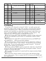
1
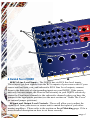
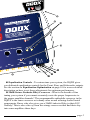
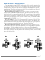
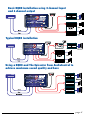
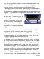
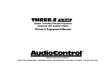
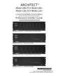
Six Channel Pre-amp Processor with Signal Delay, Equalization and
Selectable Electronic Crossover
The DQDX is your gateway to amazing sound from any aftermarket audio
system. It is a compact, six channel,
high-performance signal processor with
independent multi-channel equalization and signal delay to custom tune
the system plus a selectable electronic
crossover for precise system set-up.
In short; the DQDX can “Make
Good Sound Great”!
Key Features of The DQDX
Here are some of the unique features of the AudioControl DQDX:
• User-friendly Signal Delay to control the acoustical alignment between the
left and right channels plus the front and subwoofer channels
• Individual equalization controls for the front, rear and subwoofer channels
for simple yet precise system tuning
• Fully adjustable 24dB/Octave Linkwitz-Riley electronic crossover
• PFM (Program Frequency Match) Subsonic Filter
• Six channels of RCA line level inputs
• ACR-3 Dash Control Remote allows for control of the subwoofer level
plus processing bypass
• Discrete Input and Output level controls with clipping indicators
• Remote turn on output provides a 12-volt trigger to turn on
your amplifier
• Built in Pink Noise for easy Signal Delay and Equalizer tuning
and system set-up
• Bulletproof 5 year warranty
(when installed by an authorized AudioControl dealer)
®
Making Good Sound Great®
®
page 1
Quick Install Guide
If you are a seasoned audio enthusiast and are chomping at the bit to begin
your experience with the DQDX, we offer some Quick Install Guidelines below to help maximize your experience. Please refer to the system diagrams on
page 8 as good guidelines.
1 Physically mount the DQDX in a location that keeps it away from beverage spills, food crumbs, and curious fingers. You will want to select a location
that allows you access to the top panel controls.
2 The DQDX needs to be installed in the signal path between your source
unit (or as some may call it, “Your Radio”) and an after-market amplifier(s)..
Note: If your source unit has front, rear, and subwoofer RCA Line Level outputs, connect them to the corresponding inputs on your DQDX. If your source
unit has only front and rear inputs fear not! Just connect these to the front
and rear inputs on the DQDX and switch the “Sub to Front” jumper to the ON
position. There is a more detailed of the jumpers located under the cover in
the section titled “Under The Cover” (Duh!). Changing this jumper to ON will
route the low pass signal (as defined by your crossover selection) to the Sub
outputs of the DQDX.
3 Use RCA connecting cables to connect the RCA outputs of the DQDX to
your after market amplifier(s). If this is not obvious to you, quickly pack up
your DQDX and run to your nearest authorized AudioControl dealer to have
them perform the installation. You will thank us later.
4 Connect +12 volt power, ground and turn-on wires as needed.
Don’t forget the fuse!
5 Connect your amplifier trigger input to the 12-volt trigger output of the
DQDX.
6 VERY IMPORTANT! Make sure the input gain control on your aftermarket amplifier(s) are all the way down (usually counter clockwise).
7 Turn on the system and level match your DQDX to your source unit and
amplifiers.
8 Select the correct crossover point on your DQDX to create a Hi-Pass for
the front and rear outputs and a Low-Pass for your subwoofer output, if you
are not using the crossover on your source unit. We would always recommend
turning the crossovers OFF on your source unit and using the sweet crossover
in the DQDX.
9 On the chassis of the DQDX, set Signal Delay Mode to Set-Up.
0 Using the Dash Control, adjust the signal delay between the Left and Right
channels for optimum sound.
Tap the ACR-3 Dash Control and adjust the signal delay between the front
and subwoofer outputs.
page 2
On the chassis, change Signal Delay Mode back to Normal.
Set the equalization controls for the front, rear, and subwoofer channels.
While your ears are a good reference point, we recommend using an audio
analyzer whenever possible. To engage the pink noise output of the DQDX for
help setting up the equalizer, press and hold the ACR-3 remote knob down for
about four seconds. This will switch the outputs of the DQDX from music to
Pink Noise. When you are done setting up the Equalizer you can just press and
hold the remote again for 4 seconds and it will turn the Pink Noise output off.
Sit back and enjoy the sound
If you have made it to this point and you don’t have any questions, then
“Congratulations”! With that said we certainly encourage you to set aside
some time to grab a beverage or two and read through this entire manual, since
there is a tremendous amount of useful information. Plus we took the time to
write it so it would make us feel a whole lot better.
We now interrupt your reading of this manual to highlight a very important
feature of all AudioControl Autosound products…
Our Bulletproof Warranty
AudioControl Autosound products are designed and assembled at our factory
in the Pacific Northwest, just outside of a little town called Seattle, Washington. By nature, our products are rather sophisticated so we spend a good deal of
time training our dealers and their installation team. We do this so you will get
the best possible results from your AudioControl components.
To reinforce this point, if you have an Authorized AudioControl dealer install
your DQDX, we will extend the normal one-year warranty to a full FIVE years
parts and labor. Complete details of this warranty are listed at the end of this
manual and on our website at www.audiocontrol.com.
We now return you to your regularly
scheduled reading.
page 3
➍
➎
➌
➋
A Guided Tour of DQDX
➊
1 RCA Line-Level Inputs - The DQDX has six RCA line level inputs.
These inputs get their signals from the RCA outputs of your source unit. If your
source unit has front, rear, and subwoofer RCA Line Level outputs, connect
them to the three sets of corresponding inputs on your DQDX. If the source
unit only has one output, the Front to Sub circuitry in your DQDX selectively
routes the Front input channels to the subwoofer channels when you have the
jumper in the appropriate position (see the next section on “Under The Cover”
on internal jumper positions).
2 Input and Output Level Controls - These will allow you to adjust the
signal level from your stereo or source unit to match the input of your aftermarket amplifiers. Please refer to the section on Level Matching page 13 for a
more detailed description on how to set these correctly.
page 4
➓
➒
➑
➐
➏
3 Equalization Controls - To custom tune your system, the DQDX gives
you dedicated equalization controls for the Front, Rear, and Subwoofer outputs.
See the section on Equalization Optimization on page 10 for a more detailed
description on how to set these adjustments for optimum performance.
4 24dB/Octave Linkwitz Riley Crossover - What is the benefit of fine
tuning your system if you cannot accurately route the proper frequencies to
the proper amplifier channels? The programmable audiophile crossover in the
DQDX is the same crossover as in many other award winning AudioControl
components. Know who else gives you a 24dB Linkwitz-Riley in their EQ?
Nobody! This is also a far cry from the wimpy crossovers that find their way
into some amplifiers these days.
page 5
5 Signal Delay Mode - This allows the user to put the DQDX into Set-Up
mode and adjust the signal delay settings using the dash control. See page 9 for
details on setting this up.
6 Ground - Connect to a good, verified chassis ground (the battery is the best
possible location.) Since factory ground wires typically have multiple devices
connected to them and could cause ‘Noise’ in the audio system, we would recommend to NOT use factory ground wires or locations.
7 +12V Power - Connect to a good source of 12-Volt power. Be sure to use
a fused connection that does not exceed 2 Amp. Doing so may damage your
DQDX.
8 Remote In - This is the ‘on’ and ‘off’ selector for your DQDX. Connect this
wire directly to your source unit 12Volt trigger wire. If your source unit is not
equipped with a 12 Volt trigger wire then find a reliable source in the vehicle that
comes on when the key is in the ‘On’ position and turns off when the key is in
the ‘Off’ position.
9 Remote Out - Connect the 12 Volt turn on lead for your aftermarket amplifiers directly to this connection and not to any other. This is critical to eliminate
any ‘clicks’ or ‘pops’ during power up and power down cycles.
0 Maximized Indicators - These brightly colored LED’s indicate when the
signal level coming into and going out of your new DQDX is just below clipping. When properly level matched with your source unit these LED’s should
just barely ‘flicker’ occasionally when your system is playing at its maximum
volume level. Please refer to the section on Level Matching, page 13 for a more
detailed step by step process (trust us…. This one is important!)
Power - If you have connected all of your power wires correctly, this light
should be bright red when your system is on and ready to go!
Remote Level Control (ACR-3 Included) - In the Set-Up mode, this control is used for setting up the signal delays. In Normal mode, it will give the user
Subwoofer level control. Additionally, if you press and hold the remote down
for 4 seconds, the outputs of the DQDX will turn from music to Pink Noise.
This will assist in the proper setting of the EQ and Delay. When the DQDX is in
Normal mode, pressing the remote momentarily will defeat all processing on the
DQDX (Equalizer and Signal Delay). This is very helpful during set-up to make
sure the changes you make to the EQ and Delay made the difference you were
looking for.
Pre-Amp Outputs - These RCA plugs should be connected directly to your
amplifier inputs. Do not connect any speakers directly to your DQDX and definitely do not connect to any home appliances like your coffee maker or toaster!
Parallel Outputs - The DQDX is equipped with a unique circuit that allows for the Front input signal to feed the Subwoofer outputs. See page 12.
page 6
Under the Covers - Internal Jumpers
You can optimize your DQDX using most of the controls mounted on
the top of the chassis. However, we recognize there are situations where
advanced users may have the need to configure the DQDX for specific
applications. Therefore we have provided a few setting that are located
under the chassis top for limited access.
1 Input Balancing Jumper: For many systems you can leave this
jumper in the UNBALANCED position. In other systems, the source
unit may look for a ground through the RCA connection to the amplifier
and create a ground loop, which in turn can cause a whine (not the type
that comes in a bottle) in your system. In that event, you should set this
jumper to BALANCED.
2 PFM Jumper: The PFM (Programmable Frequency Match) Filter
controls the cutoff frequency of the subwoofer output. The PFM is the
bottom limit for the low pass output and will help protect your speakers
from a symptom commonly known as “Speaker Explodus”.
3 Ground Isolation Selector: Alternator noise may appear in a system because the source unit and amplifier(s) are using different grounding schemes. To help in this situation, we have provided alternative
grounding connections. Make sure your system is turned OFF before you
move these jumpers. We ship them in the isolated position, which usually
gives the best results.
➊
➋
➌
page 7
Basic DQDX installation using 4 channel input
and 6 channel output
Typical DQDX installation
Using a DQDX and The Epicenter from AudioControl to
achieve maximum sound quality and bass
page 8
Great Features of the DQDX
Signal Delay Operation
Because of speaker placement limitations and seating positions in a
car, the driver of the vehicle is in an incorrect acoustic alignment with the
speakers. The following steps will guide you in delaying the appropriate
speakers for just a few milliseconds, so the DQDX is able to allow the
different signals to arrive at the same time putting the driver in perfect
acoustical alignment.
1 For best performance and ease of set-up, go to our website at
www.audiocontrol.com and download the Signal Delay Set-Up App for
your Apple iPhone or iPad. It’s FREE and will help take all the guesswork out of setting up the delay. However, if you do not have access to
an iPhone or iPad, don’t worry, you can easily set up the delay just by
using your own two ears.
2 After you have made all your power and ground connections, select
your crossover point on the DQDX and set your input and output levels
correctly. Turn the Signal Delay knob on the chassis all the way to the
right to go into Set-Up Mode. You will notice that when you are in SetUp mode the Orange light on the chassis turns on and the blue light will
blink on the ACR-3 dash remote.
3 You will need to make sure that all your delay settings are at zero.
Start with the Left to Right setting (the Red light on the remote will be
solid) and turn the knob completely CLOCKWISE until you no longer
hear any Mute Clicks. Once you have verified your Left to Right is set to
zero you want to now set your Sub to Front delay at zero. Simply push
the dash remote to switch from Left to Right to Sub to Front. At this time
the blue light will continue to blink and the red light will turn off. Again,
turn the knob CLOCKWISE until you no longer hear any Mute Clicks.
You have now set all of the delay in the DQDX to zero.
4 Now you are going to want to choose your source material to listen
to while setting the delay. Choose a song that has very strong vocals
and limited instruments (we are thinking more Adele than 9 Inch Nails
on this one). This will make it much easier to “move” the image from
down at your left knee where it currently exists, up to the center of the
dash where it needs to be. Don’t laugh here but talk radio is also a great
source to set the delay because you really are able to ‘visualize’ the person’s voice moving as you adjust the delay.
page 9
5 Left / Right Delay Push on the dash remote until the blue LED
is blinking and the red LED is solid. With the source material playing,
slowly turn the dash control knob COUNTER CLOCKWISE. Each detent in the remote represents an amount of time (in milliseconds) that you
are delaying the Left Front Speaker. We have added a small Mute Click
along with the detent on the remote to help you determine your amount
of delay. Keep in mind that if you think you have gone too far you can
always start over. Just turn the knob all the way clockwise to start back at
zero and slowly turn counter clockwise until you reach your desired result. For reference in most vehicles out there today this will be between
three to five clicks.
6 Front/Subwoofer Delay Once you have dialed in your Left / Right
delay, it’s time to set up the sub. Push on the dash remote to switch
delay modes and verify that the blue light continues to blink but the red
light is off. Exactly like you did setting up the front left speaker, start by
slowly turning the knob counter clockwise to add delay to both of the
front speakers. You will notice with each Mute Click of the remote the
sub will move forward toward the driver. Again, if you think you have
gone too far or missed that ‘sweet spot’ you can always start over by just
turning the knob back all the way clockwise and repeat the process again.
Depending on the size of the vehicle this will usually be around 5 clicks
of the remote.
Once you have everything where you want it you are done! Easy right?
Now just go back to the Signal Delay knob on the cover of the DQDX
and turn it counter clockwise back to Normal mode (the blue light will
come on) and you are ready to move to the next step of set-up.
Equalization Optimization
When it comes to music, everyone has his or her own particular taste.
Some people want pounding bass and crisp, blood curdling highs. Others
may prefer a “flat” response (whatever the heck that is). At the end of the
day, most people just want their system to sound balanced and “just like
it did in the store” or similar to their buddy’s car. The following equalization guidelines should help you achieve your own personal audio nirvana
and if you are looking for more detailed information on setting equalizers
and small space acoustics please visit the support section of our website
at www.audiocontrol.com.
1 For optimum performance, get your hands on a good quality RTA
(real time analyzer); we happen to know someone who makes a really
page 10
good one. If you cannot locate an RTA, you probably want to have your
authorized AudioControl dealer perform the equalization adjustments
since they will have one. You can certainly adjust your DQDX using
your ears, however, using an RTA will give you the best results.
2 Begin playing pink noise through your system by pressing and holding the ACR-3 remote button down for 4 seconds. Place the microphone
for your analyzer on a microphone stand in the drivers seat and adjust the
height so it is where the drivers head would be while sitting. Take a careful look at the “curve” on your analyzer
and how one frequency combines with
the next. There is no one curve that will
satisfy every person, as we all have different tastes. How else can you explain
Liberace or rice cakes? The key is to
use your DQDX to help balance your
system from one frequency to the next
AudioControl Real Time Analyzer
and give your speakers the sparkle,
sizzle, detail or punch that the acoustics
of the car have compromised.
3 You will want to start equalizing by removing or cutting any large
bumps, peaks, or areas with too much energy at a particular frequency.
Next, boost the ranges that do not have enough energy. We strongly recommend that you cut or decrease energy before you boost.
4 Although the plethora of knobs on your DQDX can be intimidating,
fear not as they were designed to give enough control to maximize your
systems performance but not enough to get you in trouble. Here is an
explanation of the key areas you should focus on:
Sub-bass: 100 Hz and below – A car without bass is like a day without sunshine... unless you live where we do because most of the days in
the Pacific Northwest do not have sunshine. This area is one of the more
critical although it is also one of the most difficult to properly reproduce.
Most people prefer their bass frequencies to be 6 to 9 dB louder than the
rest of their system, although there are some crazy folks that prefer their
bass substantially louder. The key in this area is to have enough speakers and power to produce the amount of bass you desire but don’t use the
controls on the DQDX to try and force your speakers to produce sounds
they can’t. Too much bass boost creates a condition called “speakerus
explodus”, which is not pretty to hear or watch.
Midbass: 100 Hz to 300Hz – The phrase, “too much of a good thing”
can certainly apply to the midbass frequencies. This is the transition area
page 11
of the audio spectrum that is an octave above your sub-bass frequencies
and several octaves below your midrange. Most autosound systems have
too much midbass due to the fact that speakers mounted in the doors
or kick panels cause resonance’s or peaks in the response curve. These
peaks in the midbass can actually mask or block sounds in the all-important midrange area causing your system to sound dull or lifeless.
Midrange: 300Hz to 3Khz – Musical instruments, vocals, mid-range
percussion and many things we associate with imaging and staging happen in this area of the bandwidth. For that reason you will want to keep
this area as smooth and balanced as possible. Too much boosting can
make you feel like your listening to your system in a tile bathroom. Not
enough energy the midrange sounds empty and dry.
Treble: 3KHz and Up – If midrange is the cake, then these high or
upper frequencies are considered the frosting. Many autosound systems
start a gradual decline in this area which is why speaker placement is
very important. The DQDX only gives you a few controls in this area
because too much boosting can really make a speaker sound un-natural.
Digitally Selectable Electronic Crossover
Since component speakers (like woofers,
midrange and tweeters) are designed to reproduce certain frequencies, a crossover allows
you to match the speaker needs to the appropriate frequency range. The correct crossover
frequency greatly depends on your choice of
speakers. This section presents techniques for
improving your overall installation if you are
installing a bi-amplified system. We recommend choosing a crossover frequency based on your speaker manufacture’s specifications. Most manufactures list a recommended crossover
frequency as part of the speaker specifications. Choosing the correct
crossover point will provide increased speaker reliability and optimum
sound quality.
The DQDX comes with a 24/dB Octatve Linkwitz Riley alignment
crossover that lets you select the exact crossover point you need for your
system. The crossover frequency markings on your DQDX are for reference purposes only. The exact crossover frequency can be found on the
chart below. To get to the exact desired frequency simply start out with
the crossover selector turned all the way to the left (or counter clockwise) and count the position clicks until you get to the frequency you
want to use.
page 12
Pos
Freq
2
3
4
5
6
7
8
9
7:00 pos, full left rota50
tion
50
60
65
70
8:30 pos
75
80
85
90
10
95
11
100
1
Pos
Freq
12
125
13
14
15
16
17
18
19
20
150
175
200
250
300
400
500
defeat
21
defeat
1:00 pos
3:30 pos
5:30 pos, full
right rotation
Level Matching
If you have ever listened to a friend’s “killer” car audio system and
heard lots of hiss, clicks or pops, then you have experienced an improperly level-matched system. When a performance Autosound system is
properly level matched, you should get the maximum output from your
source unit and amplifiers without any clipping or annoying hiss. The
following steps will help guide you through the process!
1 Set your source unit’s fader and balance controls to their center position and your amplifier(s) gain control to a minimum (usually counter
clockwise).
2 Disconnect the output RCA connections between your DQDX and
your amplifier(s)… otherwise get some earplugs.
3 Start playing some relatively dynamic music and set the volume on
your source unit to about ¾ max volume. You should not hear anything
at this point. If you are hearing music, go back to step #2… If you are
hearing voices, please go see a doctor!
4 Starting with the DQDX input level controls, adjust the control knob
clockwise until the Input Maximized LED just begins to flicker. Do not
continue to turn past this point.
5 Now adjust the output level control until the output maximized light
starts to flicker.
6 Decrease the volume control on your source unit and turn off the
power to the system. Now re-connect the RCA’s between the DQDX and
your amplifier(s).
page 13
7 At his point you can adjust your amplifier gain control according to
the specifications of your amplifier manufacturer.
Parallel Outputs
The DQDX is equipped with AudioControl’s unique Front to Sub
circuit input that allows for the Front input signal to feed the Subwoofer
outputs, when you do not have a Subwoofer input signal available. This
allows your DQDX to accept front and rear inputs channels and give you
Front, Rear, and Subwoofer output channels. Refer to the Under The
Cover section to learn more on jumper selection.
Remote Level Control - ACR-3
The ACR-3 is a multi-function remote that used for making the initial
signal delay adjustments in the Set-Up mode and then providing level
control over the Subwoofer output in the Normal mode. This allows you
to balance the bass level with the rest of the system and then increase or
decrease as needed. An additional feature of the ACR-3 dash remote is
that it allows the signal processing of the DQDX (equalization and signal
delay) to be switched in and out of the audio circuit. That means that you
can hear the system with and without the processing to hear the difference that the tuning makes in the sound of your system.
Dash Control Placement And Mounting
The ACR-3 dash control may be mounted under the dash using its own
bracket or through a custom hole in the dash. It should be
within reach of the driver and in a spot where the LED is
plainly visible.
Bracket Installation
The dash control mounts with two
screws, which attach to the underside of the dashboard. Slide
under the dash and place the
dash control in its mountDash Control Assembly
ing position, mark the two
mounting holes, drill pilot holes, and secure with two screws.
Custom Installation
For that custom, finished look, the dash control can be flush mounted
directly on the dash-board (or anywhere else). Referencing the figure
above, disassemble the dash control from the mounting bracket. Start by
pushing the LED from its holder followed by removing the circuit board
page 14
and rotary control from the bracket. Drill a 9/32 hole in the dashboard for
the control along with a 1/8 hole for the lock tab and a 13/64 hole for the
LED holder. Reassemble the dash control components on the dashboard.
Block Diagram of the DQDX
Feeling lost? Here’s an internal “roadmap” to help you out. This simplified block diagram is a map of the paths your signals take inside the
DQDX. With this diagram you can follow each input through the processor. If you do have an issue with the hook-up of your DQDX and need
to call for technical assistance, please have this diagram available so we
can help you trace the problem and get your system up and running and
sounding as awesome as we know it can.
page 15
The WARRANTY
People are scared of warranties. Lots of fine print right? Well, fear
no more, this warranty is designed to make you rave about us to your
friends. It’s a warranty that looks out for you and helps you resist the
temptation to have your friend, “...who’s good with electronics”, attempt
to repair your AudioControl product.
Go ahead and read this warranty, and then take a few days to enjoy
your new DQDX before going on line to register your unit at
www.audiocontrolregistration.com.
We also look forward to your comments while you are registering your
DQDX. “Conditional” doesn’t mean anything ominous. The Federal
Trade Commission tells all manufacturers to use the term to indicate
that certain conditions have to be met before they’ll honor the warranty.
If you meet all of these conditions, we will warranty all materials and
workmanship on the DQDX for one year from the date you bought it
(five years if it is installed by an authorized United States AudioControl dealer). We will fix or replace it, at our option, during that time.
Here are the conditional conditions:
1 You have to go to www.audiocontrol.com warranty and register your
DQDX within 15 days after purchase.
2 You must keep your sales receipt for proof of purchase showing
when and from whom the unit was bought. We’re not the only ones who
require this, so it’s a good habit to get into with any major purchase.
3 Your DQDX must have originally been purchased from an authorized AudioControl dealer. You do not have to be the original owner, but
you do need a copy of the original sales slip.
4 You cannot let anybody who isn’t: (A) the AudioControl factory; (B)
somebody authorized in writing by AudioControl to service your DQDX.
If anyone other than (A) or (B) messes with your DQDX, that voids your
warranty.
5 The warranty is also void if the serial number is altered or removed,
or if the DQDX has been used improperly. Now that may sound like a
big loophole, but here is all we mean by it. Unwarranted abuse is: (A)
physical damage (don’t use the DQDX for a car jack); (B) improper
connections (120 volts into the power jack can fry the poor thing); (C)
sadistic things. This is the best product we know how to build, but if
you mount it to the front bumper of your car, something will go wrong.
If an authorized United States AudioControl dealer installs the DQDX,
the warranty is five years. Assuming you conform to 1 through 5, and it
page 16
really isn’t all that hard to do, we get the option of fixing your old unit or
replacing it with a new one.
LEGALESE SECTION
This is the only warranty given by AudioControl. This warranty gives
you specific legal rights that vary from state to state. Promises of how
well the DQDX will perform are not implied by this warranty. Other than
what we have covered in this warranty, we have no obligation, express or
implied. Also, we will not be obligated for direct or indirect consequential damage to your system caused by hooking up the DQDX. Failure to
register warranty information negates any service claims.
page 17
DQDX SPECIFICATIONS
All specifications are measured at 14.4 VDC (standard automotive voltage.) As technology advances, AudioControl reserves the right to continuously
change our specifications, like our Pacific Northwest weather although we are
working on it.
Maximum output level................................................................ 7.5Vrms
Output attenuation..................................................................... +/-12 dB
Frequency response............................................................. 10Hz-22kHz
Total harmonic distortion............................................................... 0.01%
Input Impedance...................................................................... 20 Kohms
Equalization Frequencies
Front/Rear... 125Hz, 175Hz, 250Hz, 500Hz, 1kHz, 2kHz, 8kHz
Sub Output... 31.5Hz, 40Hz, 50Hz, 63Hz, 80Hz, 100HZ 125Hz
Signal Delay
Left /Right Max Delay............................................................ 10 ms
Front/Sub Max Delay............................................................. 35 ms
Crossover Frequency....................................................... 50Hz to 500Hz
Crossover Slope........................................ 24dB /Octave Linkwitz-Riley
PFM Frequency................................................................ 20Hz or 30 Hz
Output Impedance ................................................................... 150 Ohms
Power supply........................................High headroom PWM switching
Power draw................................................................................... 350mA
Recommended fuse rating........................................................... 2 Amps
Remote trigger max output current ............................................... 1 Amp
Size..................................................................9.25”W x 5.75”D x 1.25”
Weight............................................................................................... 3 lbs
©2014 AudioControl, Inc. All rights reserved
AudioControl, Making Good Sound Great and DQDX are all trademarks of
AudioControl Inc. This manual was conceived, designed, and written on a cold
and windy day in the Pacific Northwest which is what the locals from Seattle
call “spring.”
®
Making Good Sound Great®
22410 70th Avenue West
Mountlake Terrace, WA 98043 USA
Phone 425-775-8461 • Fax 425-778-3166
www.audiocontrol.com
™
P/N 913-121-0