1
Release Note
Software Release 2.6.1
For AT-8900 Series Switches
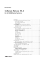
Introduction ...................................................................................................... 3
Key Hardware Features of the AT-8900 Series Switch ........................................ 4
Power Supply Units (PSUs) .......................................................................... 4
PSU LEDs on AT-8900 Switches ................................................................... 5
SFP Transceivers .......................................................................................... 5
Installing the Switch Using the Rack-mount Kit ........................................... 5
Packet Classifier ................................................................................................ 7
Configuration of Packet Matching Rules/Classifiers ..................................... 7
Configure Classifiers ................................................................................... 8
Quality of Service (QoS) .................................................................................. 10
An Overview of the QoS Mechanisms on the Switch ................................. 10
Packet Flow through the Switch ............................................................... 10
QoS Policy Configuration Rules ................................................................. 13
Destroying a QoS Element ........................................................................ 14
Classifiers ................................................................................................. 14
QoS Flow Groups ..................................................................................... 14
QoS Traffic Classes ................................................................................... 15
Default Traffic Class .................................................................................. 16
QoS Policies .............................................................................................. 16
Premarking ............................................................................................... 17
Bandwidth Metering ................................................................................ 19
Remarking ................................................................................................ 22
QoS RED Curves ....................................................................................... 24
Replacing Priorities on Egress .................................................................... 26
DiffServ Domains ............................................................................................ 28
How to Enable DiffServ QoS Functionality on the switch ........................... 30
Layer 2 Priority-based QoS .............................................................................. 32
How to Enable Layer 2 QoS Functionality on the switch ............................ 32
SET QOS QUEUE2PRIOMAP command ...................................................... 34
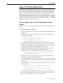
Autonegotiation of port speed and duplex mode ............................................ 34
Auto MDI/MDI-X ............................................................................................. 35
Port trunking .................................................................................................. 35
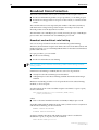
Broadcast Storm Protection ............................................................................. 36
Broadcast and multicast rate limiting ........................................................ 36
Destination lookup failure packets ............................................................ 37
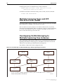
VLAN Membership of Untagged Packets ......................................................... 37
Creating VLANs .............................................................................................. 38
Creating the VLAN and Specifying the VLAN Classification ....................... 38
The Default VLAN ..................................................................................... 38
Protected VLANs ............................................................................................. 39
Multiple Spanning Trees and STP Interaction with VLANs ................................ 40
Simply connecting the world
Software Release 2.6.1
2
Overlapping VLANs Belonging to Multiple Spanning Tree Instances .................
The Ingress and Egress Rules for Layer 2 Switching ..........................................
The Ingress Rules ......................................................................................
The Egress Rules .......................................................................................
Classifier-Based Packet Filters ..........................................................................
Dynamic Port Security .....................................................................................
MAC Address Logging ....................................................................................
Changes to Proxy ARP Defaults .......................................................................
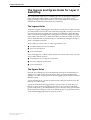
Dynamic Host Control Protocol for IPv6 ...........................................................
Configuring DHCP6 Servers ......................................................................
Configuring DHCP6 Clients ......................................................................
Setting Preference of IPv6 Dynamic Routes ......................................................
Adding an IPv6 Host with a Link-Local IP Address ............................................
Network or Broadcast Addresses Not Issued by DHCP .....................................
DHCP Compliance with RFC 2131 ..................................................................
MIB Support for DHCP Range Exhaustion Trap ................................................
Changing User Account Privilege ....................................................................
User Authentication ........................................................................................
TACACS+ .................................................................................................
S/Key ........................................................................................................
Multiple User Privilege Levels Using RADIUS ..............................................
RADIUS and TACACS Debugging .............................................................
Ping Polling of Device Reachability ..................................................................
Ping Trigger ....................................................................................................
PPPoE Client Mode on a VLAN ........................................................................
SNMP Community Names - Support for all Printable ASC11 Characters ..........
AT-8900 Series Software Release 2.6.1
C613-10391-00 REV A
40
41
41
41
42
42
43
43
44
44
45
46
47
47
48
48
48
49
49
50
51
52
53
55
56
57
Software Release 2.6.1
3
Introduction
Allied Telesyn announces the release of Software Release 2.6.1 for the AT-8900
Series switches. The AT-8900 Series Switches are a new series of high-end
Layer 3+ switches built to meet the needs of high performance network
services.
The AT-8900 Series Switches are currently represented by the AT-8948
Multi-layer Fast Ethernet Switch.
The files included in this software release are shown in the table below.
Table 1: File names for Software Release 2.6.1 on AT-8948 Switches.
Software release file
89-261.rez
CLI help file
89-261A.HLP
This release note describes the following aspects of the 2.6.1 release:
•
key hardware features of the AT-8948 switch
•
significant new software features that have been implemented in
Software Release 2.6.1 to support the AT-8900 Series switches
You should read this release note in conjunction with following documentation
for the AT-8948 switch:
•
Hardware Reference
•
Software Reference
•
Quick Install Guide
•
Quick Install Guide for the power supply unit (PSU)
•
Safety Booklet
These documents are on the Documentation and Tools CD-ROM packaged
with your switch, or you can download these documents from:
www.alliedtelesyn.co.nz/support/at8900
WARNING: Information in this release note is subject to change without notice
and does not represent a commitment on the part of Allied Telesyn
International. While every effort has been made to ensure that the information
contained within this document and the features and changes described are
accurate, Allied Telesyn International can not accept any type of liability for
errors in, or omissions arising from the use of this information.
AT-8900 Series Software Release 2.6.1
C613-10391-00 REV A
4
Release Note
Key Hardware Features of the AT-8900
Series Switch
Key hardware features of the AT-8948 Multi-layer Fast Ethernet Switch are:
•
1RU form factor
•
dual, hot-swappable, load-sharing power supply units (AC or DC
options) accessible at the rear of the switch chassis
•
front to back cooling
•
4 SFP (Small form-factor pluggable) 1000BASE-X uplink sockets
accessible on the front panel
•
48 ports with 10/100BASE-T RJ-45 connectors accessible on the front
panel
•
1 Compact Flash socket accessible on the front panel
•
1 DIMM socket for expansion of Synchronous DRAM
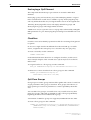
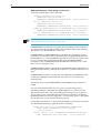
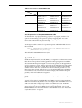
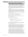
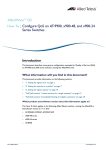
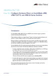
The front and rear panels of the AT-8948 switch are shown in Figure 1.
Figure 1: Front and rear panels of the AT-8948.
1
ASYN0
2
3
4
5
6
7
8
9
10
11
12
13
14
15
16
17
18
19
20
21
22
23
24
25
26
27
28
29
30
31
32
33
34
35
36
37
38
39
40
41
42
43
44
45
46
47
48
AT-8948 Enhanced Layer 3+ Switch
PSU 1
L /A
PSU 2
49
FAULT
50
CF
RESET
51
52
SFP
PORTS 49-52
L /A
LINK
ACT
SFP
ENABLED
FAULT
PWR
GOOD FAULT
L /A
D/C
PORTS 1-48
L /A
LINK 100M
ACT
LINK 10M
ACT
D/C
FULL DUP
HALF DUP
COL
FAULT
AT-PWR01
AT-FAN01
AC INPUT
100-240V
50/60Hz
3.0A
CAUTION: DISCONNECT POWER CORD PRIOR TO REMOVAL OF PSU
CAUTION: DISCONNECT ALL POWER CORDS TO DISABLE SYSTEM POWER
The AT-8948 switch is supplied with one power supply unit and one fan only
module installed as standard. To order additional power supply units, contact
your authorised Allied Telesyn distributor or reseller for more information, or
visit: www.alliedtelesyn.co.nz/support/at8900
Power Supply Units (PSUs)
The following important information applies to the AT-PWR01 power supply
units (AC only):
■
CAUTION: double pole/neutral fusing
■
The ratings of fuses FH101 and FH102 is 250 V, 5 A
This information was incorrectly omitted from the AT-8900 Series Hardware
Reference for Software Release 2.6.1.
AT-8900 Series Software Release 2.6.1
C613-10391-00 REV A
Software Release 2.6.1
5
PSU LEDs on AT-8900 Switches
When a PSU bay on the switch is empty, i.e no PSU or fan only module (FOM)
is installed, the LED for that PSU bay is lit red.
This was incorrectly specified as not lit in the AT-8900 Series Hardware Reference,
AT-8900 Series Quick Install Guide, and AT-PWR01 Quick Install Guide for
Software Release 2.6.1
SFP Transceivers
An additional SFP transceiver has been approved for use with AT-8900 Series
switches:
■
AT-MG8LX10 10km LX SFP
This information was incorrectly omitted from the AT-8900 Series Hardware
Reference for Software Release 2.6.1.
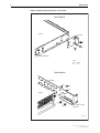
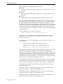
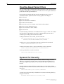
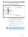
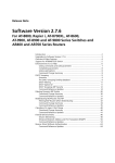
Installing the Switch Using the Rack-mount Kit
A 19 inch rack-mount kit is supplied with the AT-8948 switch. To install the
switch using the rack-mount kit:
1.
Ensure the rack has sufficient space for the switch and its associated cables.
2.
Remove the rubber feet from the switch.
3.
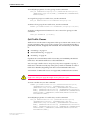
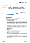
Screw the brackets to the sides of the switch using the supplied M4 screws
(see Figure 2).
4.
Fit the adjustable bracket extension onto the rear bracket but do not fully
tighten the nuts. You may need to adjust the position of the extension
bracket to correctly fit the switch into the rack (see Figure 2).
5.
Mount the switch in the rack using appropriate rack mounting screws (not
supplied).
This information was incorrectly omitted from the AT-8900 Quick Install Guide
for Software Release 2.6.1.
AT-8900 Series Software Release 2.6.1
C613-10391-00 REV A
6
Release Note
Figure 2: Fitting rack-mount brackets on the switch
Front Bracket
Switch
Bracket
A
A
A
Rear bracket
Key:
A
B
screw
nut
Rear Bracket
Bracket
A
A
A
Switch
B
B
Adjustable bracket
extension
8900RM
AT-8900 Series Software Release 2.6.1
C613-10391-00 REV A
Software Release 2.6.1
7
Packet Classifier
The Generic Packet Classifier, or Classifier, performs packet classification. The
Classifier defines packet matching rules that classify packets into data flows. A
data flow is a categorisation of packets that obey a predefined rule and are
processed in a similar manner.
After you have defined the packet matching rules in the Classifier, other
software features are used to specify what action is taken on a packet that
matches the rule.
You must create an association between the rule in the Classifier and an action
elsewhere. See “Quality of Service (QoS)” on page 10 and “Classifier-Based Packet
Filters” on page 42.
Configuration of Packet Matching Rules/Classifiers
You can create a set of packet matching rules, or classifiers. These classifiers can
identify any single packet based upon the following criteria:
AT-8900 Series Software Release 2.6.1
C613-10391-00 REV A
■
Ethernet encapsulation type
Packets are classified depending on the specific protocol type of each
frame. Different values indicate how the packet is formatted. For example,
a value of 802.2 indicates the packet is formatted according to IEEE
standards 802.2 and 802.3 with a Destination Service Access Point/Source
Service Access Point (DSAP/SSAP) value not equal to AAAA in
hexadecimal; SAP encapsulation. A value of ETHII indicates the packet is
formatted according to RFC 894; Ethernet II encapsulation.
■
Source/Destination MAC address
All frames from a specific source or destination MAC address are classified
to the same VLAN and/or priority. This classification can be used for users
on remote networks.
■
Layer 3 protocols
Frames are classified based on any value for Layer 3 protocols. The silicon
can match on all IP or IPX packets irrespective of the exact type of Ethernet
encapsulation. Layer 3 protocol and Ethernet encapsulation types are
interrelated, e.g. IPX Ethernet II encapsulated packets are different to IPX
NETWARERAW encapsulated packets.
■
Source/destination IP address
Frames are classified based on an exact match of the source or destination
IP address information within the IP header of each frame.
■
Destination IPX address
Frames are classified based on specific information contained within the
header of an IPX frame.
■
Layer 4 protocol (TCP/UDP, etc.)
Frames are classified based on specific Layer 4 TCP or UDP destination
and source port numbers contained within the header of an IP frame.
■
Layer 4 source/destination port
Frames are classified based on a specific port number or a range of port
numbers.
■
Source VLAN
Frames are classified based on the unique name of the source destination
VLAN.
8
Release Note
Configure Classifiers
To create a classifier, use the command:
CREATE CLASSIFIER=rule-id [MACDADDR={macadd|ANY}]
[MACSADDR={macadd|ANY}] [MACTYPE={L2UCAST|L2MCAST|
L2BCAST|ANY}] [VLAN={vlan-name|1..4094|ANY}]
[ETHFORMAT={802.2-TAGGED|802.2-UNTAGGED|ETHII-TAGGED|
ETHII-UNTAGGED|NETWARERAW-TAGGED|NETWARERAW-UNTAGGED|
SNAP-TAGGED|SNAP-UNTAGGED|ANY}] [PROTOCOL={protocoltype|
ANY}] [IPDADDR={ipaddmask|ANY}] [IPSADDR={ipaddmask|ANY}]
[IPDSCP={dscplist|ANY}] [IPPROTOCOL={TCP|UDP|ICMP|IGMP|
ipprotocolnum|ANY|NONTCPUDP}] [IPTOS={0..7|ANY}]
[IPXDADDR={ipxadd|ANY}] [IPXDSOCKET={NCP|SAP|RIP|NNB|
DIAG|NLSP|IPXWAN| ipxsocketnum|ANY}] [IPXSSOCKET={NCP|SAP|
RIP|NNB|DIAG|NLSP|IPXWAN|ipxsocketnum|ANY}]
[TCPDPORT={portid|ANY}] [TCPSPORT={portid|ANY}]
[UDPDPORT={portid|ANY}] [UDPSPORT={portid|ANY}]
To modify a classifier, use the command:
SET CLASSIFIER=rule-id [MACDADDR={macadd|ANY}]
[MACSADDR={macadd|ANY}] [MACTYPE={L2UCAST|L2MCAST|
L2BCAST|ANY}] [VLAN={vlan-name|1..4094|ANY}]
[ETHFORMAT={802.2-TAGGED|802.2-UNTAGGED|ETHII-TAGGED|
ETHII-UNTAGGED|NETWARERAW-TAGGED|NETWARERAW-UNTAGGED|
SNAP-TAGGED|SNAP-UNTAGGED|ANY}] [PROTOCOL={protocoltype|
ANY}] [IPDADDR={ipaddmask|ANY}] [IPSADDR={ipaddmask|ANY}]
[IPDSCP={dscplist|ANY}] [IPPROTOCOL={TCP|UDP|ICMP|IGMP|
ipprotocolnum|ANY|NONTCPUDP}] [IPTOS={0..7|ANY}]
[IPXDADDR={ipxadd|ANY}] [IPXDSOCKET={NCP|SAP|RIP|NNB|
DIAG|NLSP|IPXWAN| ipxsocketnum|ANY}] [IPXSSOCKET={NCP|SAP|
RIP|NNB|DIAG|NLSP|IPXWAN|ipxsocketnum|ANY}]
[TCPDPORT={portid|ANY}] [TCPSPORT={portid|ANY}]
[UDPDPORT={portid|ANY}] [UDPSPORT={portid|ANY}]
Note that if an ETHFORMAT parameter option is specified, the option must
include either TAGGED or UNTAGGED. For example, either ETHII-TAGGED
or ETHII-UNTAGGED, NETWARERAW-TAGGED or
NETWARERAW-UNTAGGED, etc.
The available ETHFORMAT and PROTOCOL parameter combinations and
their implementation in the Classifier are shown Table 2.
Table 2: Available ETHFORMAT and PROTOCOL parameter combinations
ETHFORMAT=
PROTOCOL=
CLASSIFIER
ASIC Chip
ETHII
[not specified]
OK
Error
ANY
OK
Error
IP
OK (1)
Ok
IPX
OK (2)
OK
protocoltype
OK
OK
[not specified]
OK (3)
OK
ANY
OK (3)
OK
IP
Error
n/a
IPX
OK (3)
OK
“IPX 802.3”
OK
OK
protocoltype
Error
n/a
NETWARERAW
AT-8900 Series Software Release 2.6.1
C613-10391-00 REV A
Software Release 2.6.1
9
Table 2: Available ETHFORMAT and PROTOCOL parameter combinations
ETHFORMAT=
PROTOCOL=
CLASSIFIER
ASIC Chip
SNAP
[not specified]
OK
Error
ANY
OK
Error
IP
OK
OK Protocol=xxxxxx0800
IPX
OK
OK Protocol=xxxxxx8137
protocoltype
OK
OK
[not specified]
OK
Error
ANY
OK
Error
IP
Error
n/a
IPX
OK (4)
OK
protocoltype
OK
OK
802.2
Key to table:
■
[not specified] = the PROTOCOL parameter is not specified on the
command line
■
(1) = equivalent to specifying PROTOCOL=0800
■
(2) = equivalent to specifying PROTOCOL=8137
■
(3) = equivalent to specifying PROTOCOL=”IPX 802.3”
■
(4) = equivalent to specifying PROTOCOL=E0.
To display the output of the SHOW CLASSIFIER command and packet
matching rules, use the command:
SHOW CLASSIFIER=rule-id [MACDADDR={macadd|ANY}]
[MACSADDR={macadd|ANY}] [MACTYPE={L2UCAST|L2MCAST|
L2BCAST|ANY}] [VLAN={vlan-name|1..4094|ANY}]
[ETHFORMAT={802.2-TAGGED|802.2-UNTAGGED|ETHII-TAGGED|
ETHII-UNTAGGED|NETWARERAW-TAGGED|NETWARERAW-UNTAGGED|
SNAP-TAGGED|SNAP-UNTAGGED|ANY}] [PROTOCOL={protocoltype|
ANY}] [IPDADDR={ipaddmask|ANY}] [IPSADDR={ipaddmask|ANY}]
[IPDSCP={dscplist|ANY}] [IPPROTOCOL={TCP|UDP|ICMP|IGMP|
ipprotocolnum|ANY|NONTCPUDP}] [IPTOS={0..7|ANY}]
[IPXDADDR={ipxadd|ANY}] [IPXDSOCKET={NCP|SAP|RIP|NNB|
DIAG|NLSP|IPXWAN| ipxsocketnum|ANY}] [IPXSSOCKET={NCP|SAP|
RIP|NNB|DIAG|NLSP|IPXWAN|ipxsocketnum|ANY}]
[TCPDPORT={portid|ANY}] [TCPSPORT={portid|ANY}]
[UDPDPORT={portid|ANY}] [UDPSPORT={portid|ANY}]
For detailed information about how to configure classifiers, see the Generic
Packet Classifier chapter of the AT-8900 Series Software Reference.
AT-8900 Series Software Release 2.6.1
C613-10391-00 REV A
10
Release Note
Quality of Service (QoS)
Quality of Service refers to the ability to intelligently manage network traffic to
allow stable and predictable end-to-end network performance. QoS
mechanisms enable:
■
the prioritisation of network traffic
■
the management of the bandwidth available to that traffic
On the AT-8948 switch, QoS controls are applied to traffic ingressing ports.
Therefore, to control a particular type of traffic, an appropriate QoS policy
must be attached to each port that type of traffic ingresses.
An Overview of the QoS Mechanisms on the Switch
QoS is a broadly used term that encompasses as a minimum both Layer 2 and
Layer 3 in the OSI model.
Quality of Service is typically demonstrated by how the switch:
■
assigns priority to incoming frames, if they do not carry priority
information
■
maps prioritised frames to traffic classes, or maps frames to traffic classes
based upon other criteria
■
maps traffic classes to egress queues, or maps prioritised frames to egress
queues
■
provides minimum and maximum bandwidth guarantees for traffic
classes, egress queues, and/or ports
■
schedules frames in egress queues for transmission (for example, empty
queues in strict priority or sample each queue)
■
relabels the priority of outgoing frames
■
determines which frames to drop, remark or requeue if the network
becomes congested
■
determines which frames to drop if the network becomes congested
■
reserves memory for switching/routing or QoS operation (e.g. reserving
buffers for egress queues, or buffers to store packets with particular
characteristics)
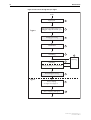
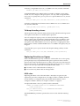
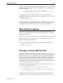
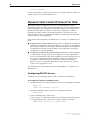
Packet Flow through the Switch
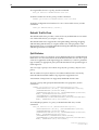
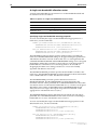
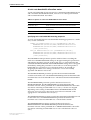
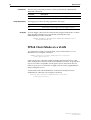
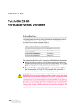
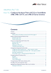
The flow of a packet through the switch’s QoS engine are shown in Figure 3 on
page 12 and Figure 4 on page 13. Figure 3 includes for reference the processing
points at which the switch determines whether the packet is to be bridged
(layer 2 switched) or routed (layer 3 switched). Each stage in the packet
processing is numbered in Figure 3 and summarised in Table 3.
AT-8900 Series Software Release 2.6.1
C613-10391-00 REV A
Software Release 2.6.1
11
Table 3: Stages in the packet processing for QoS
Stage
Description
For more information
1
The packet arrives at the ingress port.
“Switch Ports”, Switching chapter,
AT-8900 Series Software
Reference.
2
For tagged packets, the switch maps the packet’s initial VLAN tag User
Priority value to an egress queue.
“How to Enable Layer 2 QoS
Functionality on the switch” on
page 32
For untagged packets, the switch assigns the packet to the default queue.
3
The switch determines whether the packet is to be bridged (layer 2 switched) “The Layer 2 Switching Process”,
or routed (layer 3 switched). If it is to be bridged, the switch determines what Switching chapter, AT-8900 Series
its destination port or ports will be.
Software Reference.
4
The switch classifies the packet. Classification sorts traffic into data flows.
5
If you configure premarking, the switch replaces one or both of the packet’s “Premarking” on page 17
initial DSCP or VLAN tag User Priority values, or assigns the packet to a
bandwidth class or an egress queue.
6
If you configure metering, the switch measures how much bandwidth the “Bandwidth Metering” on page 19
packet uses. From this, it determines whether or not the packet conforms to
the bandwidth specifications of the data flow to which the packet belongs.
7
If you configure remarking, the switch remarks the packet as a result of the
metering. Like premarking, remarking involves changing one or both of the
packet’s DSCP or VLAN tag User Priority values, or assigning the packet to a
bandwidth class or an egress queue.
8
The switch determines whether the packet is to be routed (layer 3 switched) Internet Protocol (IP) chapter,
and if so, what its destination port or ports will be.
AT-8900 Series Software
Reference, for information about
IP.
9
The switch determines whether the appropriate egress queue has room for
the packet. If the queue has room, the switch puts the packet in that queue.
If the queue is congested, the switch may discard the packet instead,
according to the default tail drop scheme or the configured RED curve or tail
drop scheme.
“Remarking” on page 22, and the
DROPBWCLASS3 parameter of the
CREATE QOS TRAFFICCLASS
command, Quality of Service
chapter
, AT-8900 Series Software
If you configure dropping bandwidth class 3, the switch discards the packet
Reference
.
if it does not conform to the bandwidth specifications of the data flow.
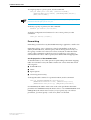
For a detailed diagram of this stage, see Figure 4 on page 13.
10
Generic Packet Classifier chapter,
AT-8900 Series Software
Reference.
“QoS RED Curves” on page 24,
“Tail-drop discarding scheme” on
page 26, and the SET QOS PORT
EGRESSQUEUE command, Quality
of Service chapter, AT-8900 Series
Software Reference.
The Egress Queue Scheduler empties the queues according to the default or The SCHEDULER parameter of the
configured scheme, at a rate that does not exceed the bandwidth available SET QOS PORT EGRESSQUEUE
command, Quality of Service
at the egress port. The packet leaves out the egress port.
chapter
, AT-8900 Series Software
For a detailed diagram of this stage, see Figure 4 on page 13.
Reference.
The EGRESSLIMIT parameter of the
SET SWITCH PORT command,
Switching chapter, AT-8900 Series
Software Reference.
AT-8900 Series Software Release 2.6.1
C613-10391-00 REV A
12
Release Note
Figure 3: Packet flow through the QoS engine
Packet
Ingress
Ingress port
1
Tagged: priority mapped to queue
Untagged: mapped to default queue
2
Bridging processing
3
Classification
4
Premarking
5
Remarking
7
6
Metering
Limiting (dropping non-conformant)
IPv4 routing processing
8
Egress
Queue shaping
See Figure 4 on page 13
9
Queue emptying and egress
10
AT-8900 Series Software Release 2.6.1
C613-10391-00 REV A
Software Release 2.6.1
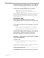
13
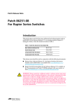
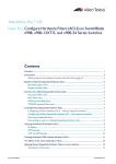
Figure 4: Detailed packet flow at the queueing and egress stages of Figure 3 on
page 12
Packet
RED curve or
tail-drop processor
Information
about queue
congestion
level
Queue is
congested
Dropped
Queue
has room
Q QQQQQQQ
Egress queues 0 - 7
Bandwidth of
each queue can
be set separately
Information
about how much
bandwidth is
available on
the port
Scheduler
Egress port
QoS Policy Configuration Rules
The QoS policy configuration rules on the switch are:
AT-8900 Series Software Release 2.6.1
C613-10391-00 REV A
1.
A classifier may be assigned to many flow groups. However, assigning a
classifier more than once within the same policy may lead to undesirable
results. A classifier may be used successfully in many different policies.
2.
A flow group may have many classifiers.
3.
A flow group may only be assigned to one traffic class.
4.
A traffic class may have many flow groups.
5.
A traffic class may only be assigned to one policy.
6.
A policy may have many traffic classes.
7.
A policy may be assigned to many ports.
8.
A port may only have one policy.
14
Release Note
Destroying a QoS Element
The components that make up a QoS solution are created as individual
elements.
Destroying a policy will not destroy any of the underlying entities. A logical
link is created when a traffic class is added to a policy. Destroying the policy
will only unlink the traffic class, leaving the traffic class in an unassigned state.
Similarly, destroying traffic classes will simply unlink flow groups and
destroying flow groups will simply unlink classifiers.
A RED curve set (see “QoS RED Curves” on page 24) is referenced by setting the
RED parameter on a port. Destroying the port settings leaves the RED curve set
intact.
Classifiers
Classifiers are used to identify a particular traffic flow and range from general
to specific.
Do not use a single classifier in different flows that will end up, via traffic
classes, assigned to the same policy. Use a classifier only once per policy.
To create a classifier, use the command:
CREATE CLASSIFIER
For detailed information about how to configure classifiers, see the Generic
Packet Classifier chapter of the AT-8900 Series Software Reference for Software
Release 2.6.1.
To assign classifiers to a flow group, use the command:
ADD QOS FLOWGROUP=flowgroup-id CLASSIFIER=classifier-list
To delete one or more classifiers from a flow group, use the command
DELETE QOS FLOWGROUP=flowgroup-id
CLASSIFIER={classifier-list|ALL}
QoS Flow Groups
Flow groups are used to group similar traffic together and consist of a small set
of QoS parameters and a group of classifiers. Flow groups allow the use of
more specific QoS controls in preference to controls specified by the traffic
class.
You can add a flow group to one traffic class only. A traffic class may have
many flow groups, and traffic is matched in order of flow group identifier,
beginning from the lowest numbered flow group.
A maximum of 1024 flow groups are supported, numbered from 0 to 1023.
To create a flow group, use the command:
CREATE QOS FLOWGROUP=flowgroup-list [DESCRIPTION=description]
[MARKVALUE={dscp-value|NONE}] [PREMARKING={USEMARKVALUE|
USEDSCP|NONE}]
AT-8900 Series Software Release 2.6.1
C613-10391-00 REV A
Software Release 2.6.1
15
To modify the properties of a flow group, use the command:
SET QOS FLOWGROUP=flowgroup-list [DESCRIPTION=description]
[MARKVALUE={dscp-value|NONE}] [PREMARKING={USEMARKVALUE|
USEDSCP|NONE}]
To assign flow groups to a traffic class, use the command:
ADD QOS TRAFFICCLASS=tcid FLOWGROUP=flowgroup-list
To delete a flow group from a traffic class, use the command:
DELETE QOS TRAFFICCLASS=tcid FLOWGROUP={flowgroup-list|ALL}
To display configuration information for one or more flow groups, use the
command:
SHOW QOS FLOWGROUP [={id|ALL}]
QoS Traffic Classes
Traffic classes are the central component of the QoS solution and consist of a set
of QoS parameters and a group of flow groups. You can specify that traffic is
premarked, metered, dropped, and remarked. This functionality is described
in:
■
“Premarking” on page 17
■
“Bandwidth Metering” on page 19
■
“Remarking” on page 22
If packets do not match these traffic classes they are handled by the default
traffic class. The default traffic class is described below.
You can assign a traffic class to one policy only. Once assigned to a policy, a
traffic class cannot be used by any other policy. Traffic is matched in order of
traffic class identifier, beginning from the lowest numbered traffic class.
A maximum of 1024 traffic classes are supported, numbered from 0 to 1023.
The switch cannot check that the maximum bandwidth is available to this
traffic class until you apply the traffic class’s policy to a port.
To create a traffic class, use the command:
CREATE QOS TRAFFICCLASS=id-list [DESCRIPTION=description]
[DROPBWCLASS3={YES|NO}] [IGNOREBWCLASS={YES|NO}]
[MARKVALUE={dscp-value|NONE}] [MAXBANDWIDTH={bandwidth|
NONE}] [MAXBURSTSIZE=burstsize] [MINBANDWIDTH={bandwidth|
NONE}] [MINBURSTSIZE=burstsize] [PREMARKING={USEMARKVALUE|
USEDSCP|NONE}] [REMARKING={USEDSCPMAP|BWCLASS|PRIORITY|
PRIO+BWCLASS|NONE}]
To modify the properties of a traffic class, use the command:
SET QOS TRAFFICCLASS=id-list [DESCRIPTION=description]
[DROPBWCLASS3={YES|NO}] [IGNOREBWCLASS={YES|NO}]
[MARKVALUE={dscp-value|NONE}] [MAXBANDWIDTH={bandwidth|
NONE}] [MAXBURSTSIZE=burstsize] [MINBANDWIDTH={bandwidth|
NONE}] [MINBURSTSIZE=burstsize] [PREMARKING={USEMARKVALUE|
USEDSCP|NONE}] [REMARKING={USEDSCPMAP|BWCLASS|PRIORITY|
PRIO+BWCLASS|NONE}]
AT-8900 Series Software Release 2.6.1
C613-10391-00 REV A
16
Release Note
To assign traffic classes to a policy, use the command:
ADD QOS POLICY=id TRAFFICCLASS=tcid-list
To delete a traffic class from a policy, use the command:
DELETE QOS POLICY=id TRAFFICCLASS={tcid-list|ALL}
To display configuration information for one or more traffic classes, use the
command:
SHOW QOS TRAFFICCLASS[={id|ALL}]
Default Traffic Class
The default traffic class provides a catch-all for any traffic that does not match
one of the traffic classes you assign to a policy.
The default traffic class supports the same premarking, metering, dropping
and remarking functionality as a regular traffic class. The properties of the
default traffic class are created and modified using the CREATE QOS POLICY
and SET QOS POLICY commands.
QoS Policies
QoS Policies consist of a collection of user defined traffic classes and the default
traffic class. For more information about the default traffic class see above. QoS
controls are applied to traffic ingressing ports. Therefore, to control a particular
type of traffic, an appropriate policy must be attached to each port that type of
traffic ingresses.
You can assign a policy to more than one port, but a port may only have one
policy.
The AT-8900 Series Software Reference for Software Release 2.6.1 incorrectly
states that the maximum number of QoS policies supported is 512.
A maximum of 256 policies are supported, numbered from 0 to 255.
To create a policy and specify the default traffic class properties, use the
command:
CREATE QOS POLICY=id-list [DESCRIPTION=description]
[DTCDROPBWCLASS3={YES|NO}] [DTCIGNOREBWCLASS={YES|NO}]
[DTCMAXBANDWIDTH={bandwidth|NONE}]
[DTCMAXBURSTSIZE=burstsize] [DTCMINBANDWIDTH={bandwidth|
NONE}] [DTCMINBURSTSIZE=burstsize]
[DTCPREMARKING={USEMARKVALUE|USEDSCP|NONE}]
[DTCREMARKING={USEDSCPMAP|BWCLASS|PRIORITY|PRIO+BWCLASS|
NONE}] [MARKVALUE={dscp-value|NONE}]
To modify the properties of a policy or the default traffic class, use the
command:
SET QOS POLICY=id-list [DESCRIPTION=description]
[DTCDROPBWCLASS3={YES|NO}] [DTCIGNOREBWCLASS={YES|NO}]
[DTCMAXBANDWIDTH={bandwidth|NONE}]
[DTCMAXBURSTSIZE=burstsize] [DTCMINBANDWIDTH={bandwidth|
NONE}] [DTCMINBURSTSIZE=burstsize]
[DTCPREMARKING={USEMARKVALUE|USEDSCP|NONE}]
[DTCREMARKING={USEDSCPMAP|BWCLASS|PRIORITY|PRIO+BWCLASS|
NONE}] [MARKVALUE={dscp-value|NONE}]
AT-8900 Series Software Release 2.6.1
C613-10391-00 REV A
Software Release 2.6.1
17
To assign a policy to a port or ports, use the command:
SET QOS PORT={port-list|ALL} [POLICY={id|NONE}]
[DEFAULTQUEUE=queue-number] [FORCEDEFQUEUE={YES|NO}]
[RED={red-id|NONE}]
Note that error checking of parameters and parameter values for the policy is only
performed when the policy is set on a port.
To destroy a policy or policies, use the command:
DESTROY QOS POLICY={id-list|ALL}
To display configuration information for one or more policies, use the
command:
SHOW QOS POLICY[={id|ALL}]
Premarking
Premarking occurs before any bandwidth metering is applied to a traffic class.
Premarking allows you to select new values for the DiffServ Code Point
(DSCP), bandwidth class, internal queue, and VLAN Tag User Priority of a
flow group or traffic class. These new values are based on either the DSCP
values of the constituents of the flow group or traffic class, or by using a
nominated mark-value to index a preset, user defined DSCP mapping table.
Set the properties of the DSCPMAP table
As described above, one of the options for premarking is the DSCP mapping
table. For each DSCP value, the table contains new values which the switch
will assign for:
■
bandwidth class
■
DSCP
■
Egress Queue
■
VLAN Tag User Priority
To change the table’s entries for a particular DSCP, use the command:
SET QOS DSCPMAP=PREMARKING DSCP=dscp-list
[NEWBWCLASS=bandwidth-class] [NEWDSCP=dscp-value]
[NEWPRIORITY=vlan-priority] [NEWQUEUE=queuenumber]
For NEWDSCP, the table’s initial value is the value specified in the DSCP
parameter. For NEWBWCLASS, the initial value is 1. For NEWPRIORITY and
NEWQUEUE, the initial value is 0 (zero). If you specify any one of these
parameters, you must specify a value for it; there is no default.
AT-8900 Series Software Release 2.6.1
C613-10391-00 REV A
18
Release Note
Apply premarking to a flow group or traffic class
To specify premarking, use the commands:
CREATE QOS FLOWGROUP=flowgroup-list
[MARKVALUE={dscp-value|NONE}]
PREMARKING={USEMARKVALUE|USEDSCP|NONE} [other-parameters]
SET QOS FLOWGROUP=flowgroup-list
[MARKVALUE={dscp-value|NONE}]
PREMARKING={USEMARKVALUE|USEDSCP|NONE} [other-parameters]
CREATE QOS TRAFFICCLASS=id-list [MARKVALUE={dscp-value|NONE}]
PREMARKING={USEMARKVALUE|USEDSCP|NONE} [other-parameters]
SET QOS TRAFFICCLASS=id-list [MARKVALUE={dscp-value|NONE}]
PREMARKING={USEMARKVALUE|USEDSCP|NONE} [other-parameters]
If PREMARKING is specified for a flow group, these settings override the
PREMARKING settings specified for a traffic class.
If PREMARKING=USEDSCP is specified, the QoS settings for the traffic flow
are selected from the DSCPMAP table using the DSCP value in the matching
data frames and a bandwidth class value of 1.
If PREMARKING=USEMARKVALUE is specified, the QoS settings for the
traffic flow are selected from the DSCPMAP table using MARKVALUE and a
bandwidth class of 1. The MARKVALUE parameter specifies an explicit value
to use as an index into the DSCPMAP table when the PREMARKING
parameter is set to USEMARKVALUE. MARKVALUE must be set to a valid
DSCP value to allow this action.
If PREMARKING=NONE is specified for the CREATE QOS FLOWGROUP or
SET QOS FLOWGROUP command, the traffic flow is passed to the traffic class
stage.
If PREMARKING=NONE is specified for the CREATE QOS TRAFFICCLASS
or SET QOS TRAFFICCLASS command, the traffic flow is passed to the
metering stage.
The default value for the PREMARKING and MARKVALUE parameters is
NONE.
You can set the default traffic class for a policy to premarking using a
DSCPMAP setting for which the new bandwidth class is 2. This forces the
default traffic class into a lower forwarding preference group for all queues,
ensuring that “legal” classified traffic is processed in preference. In addition,
the default traffic class may be mapped to a lower priority queue, or the queue
may be placed in a lower priority arbitration group.
For the default traffic class, to specify that premarking occurs before any traffic
class bandwidth metering is applied, use the commands:
CREATE QOS POLICY=id-list DTCPREMARKING={USEMARKVALUE|
USEDSCP|NONE} [MARKVALUE={dscp-value|NONE}]
[other-parameters]
SET QOS POLICY=id-list DTCPREMARKING={USEMARKVALUE|USEDSCP|
NONE} [MARKVALUE={dscp-value|NONE}] [other-parameters]
AT-8900 Series Software Release 2.6.1
C613-10391-00 REV A
Software Release 2.6.1
19
Bandwidth Metering
Metering allows you to select and specify the limits of the bandwidth
allocation meter that measures the bandwidth used by a traffic class.
You can select either a single-rate bandwidth allocation meter, or twin-rate
bandwidth allocation meter.
A twin-rate bandwidth allocation meter gives you greater sophistication in the
management of traffic flows than a single-rate bandwidth allocation meter
provides.
Based on the conformance of the traffic class to the bandwidth allocation meter
limits, you can then specify that traffic is dropped, and/or that the QOS
properties of the traffic flow are remarked.
The meter resolution varies according to the specific rate limits set. To ensure
that the meter operates as closely as possible to the exact specified limits an
adaptive meter rate calculation algorithm is used. The metering process
supports a variable, user-defined tolerance to bursts of traffic (burstsize), in
excess of the defined limits.
Bandwidth conformance classes
The bandwidth allocation meters employ a three-level bandwidth
conformance class, or bandwidth class, classification scheme against which
traffic is measured. The service level for each bandwidth class marker is shown
in Table 4.
Table 4: Bandwidth conformance classes.
Bandwidth class marker
Service level
Bandwidth class 1
Best conformance; best access to available
bandwidth; highest performance
Bandwidth class 2
Discretionary access to bandwidth
Bandwidth class 3
Lowest conformance; over acceptable limits, lowest
performance
The bandwidth class marker provides a preferential service level for
conforming traffic, while permitting the flexible treatment of marginal or
non-conforming traffic during the remarking, congestion control, and egress
stages.
How bandwidth and burstsize are specified
Bandwidth is specified in kilobits per second (kbps), in the range 0 to 16000000
kbps. You can specify this value in kbps, Mbps, or Gbps. If no unit suffix is
specified, the value is read as kbps. If Mbps or Gbps is specified, the value may
contain a decimal fraction, for example, 1.25 Mbps.
Burstsize is specified kilobytes (kbytes), in the range of 0 to 16000000 kbytes.
You can specify this value in kbytes, Mbytes, or Gbytes. If no unit suffix is
specified, the value is read as kbytes. If Mbytes or Gbytes is specified, the value
may contain a decimal fraction, for example, 1.25 Mbytes.
AT-8900 Series Software Release 2.6.1
C613-10391-00 REV A
20
Release Note
A single-rate bandwidth allocation meter
A single-rate bandwidth allocation meter has one bandwidth threshold and
two burstsize levels. See Table 5.
Table 5: Properties of a single-rate bandwidth allocation meter
Bandwidth class marker
Service level
Bandwidth class 1
Under maximum rate and under minimum burstsize.
Bandwidth class 2
Bursting between minimum and maximum burstsize.
Bandwidth class 3
Over maximum rate and over maximum burstsize.
Specifying single-rate bandwidth metering properties
To create and modify the single-rate bandwidth metering properties for a
traffic class, use the commands:
CREATE QOS TRAFFICCLASS=id-list [DROPBWCLASS3={YES|NO}]
MAXBANDWIDTH={bandwidth|NONE} MAXBURSTSIZE=burstsize
MINBURSTSIZE=burstsize [other-parameters]
SET QOS TRAFFICCLASS=id-list [DROPBWCLASS3={YES|NO}]
MAXBANDWIDTH={bandwidth|NONE} MAXBURSTSIZE=burstsize
MINBURSTSIZE=burstsize [other-parameters]
The DROPBWCLASS3 parameter specifies whether frames exceeding the
traffic class MAXBANDWIDTH setting are dropped. Setting this parameter to
YES indicates that data received on this traffic class at a rate higher than the
combined MAXBANDWIDTH and MAXBURSTSIZE settings allow is dropped
immediately. Setting this parameter to NO marks non-conforming traffic as
bandwidth class 3 and allows non-conforming traffic to be selected for
dropping by the RED curve settings, which have a more TCP-friendly
algorithm. The default value is NO.
The MAXBANDWIDTH parameter specifies the bandwidth available to the
traffic class. The MAXBANDWIDTH parameter determines the maximum data
rate for bandwidth class 1 and 2. The default is NONE.
The MAXBURSTSIZE parameter specifies the burst tolerance for
MAXBANDWIDTH. The MAXBURSTSIZE parameter determines the
maximum amount of data permitted above MAXBANDWIDTH for the traffic
class before frames are remarked to bandwidth class 3, or frames are dropped
depending on the setting of DROPBWCLASS3. MAXBURSTSIZE should
always be as least as large as the largest size packet to be metered on the
aggregate flow. The default value is 0 (zero).
The MINBURSTSIZE parameter determines the maximum amount of data
permitted above MAXBANDWIDTH for the traffic class before remarking to
bandwidth class 2 occurs. The default value is 0 (zero).
To create and modify the single-rate bandwidth metering properties for the
default traffic class, use the commands:
CREATE QOS POLICY=id-list [DTCDROPBWCLASS3={YES|NO}]
DTCMAXBANDWIDTH={bandwidth|NONE}
DTCMAXBURSTSIZE=burstsize
DTCMINBURSTSIZE=burstsize [other-parameters]
SET QOS POLICY=id-list [DTCDROPBWCLASS3={YES|NO}]
DTCMAXBANDWIDTH={bandwidth|NONE}
DTCMAXBURSTSIZE=burstsize
DTCMINBURSTSIZE=burstsize [other-parameters]
AT-8900 Series Software Release 2.6.1
C613-10391-00 REV A
Software Release 2.6.1
21
A twin-rate bandwidth allocation meter
A twin-rate bandwidth allocation meter has a minimum bandwidth threshold
and a maximum bandwidth threshold, and one level of burst per minimum
and maximum threshold. See Table 6.
Table 6: Properties of a twin-rate bandwidth allocation meter
Bandwidth class marker
Service level
Bandwidth class 1
Under minimum rate and under minimum burstsize.
Bandwidth class 2
Over minimum rate and burstsize and under maximum rate
and burstsize.
Bandwidth class 3
Over maximum rate and maximum burstsize.
Specifying twin-rate bandwidth metering properties
To create and modify the twin-rate bandwidth metering properties for a traffic
class, use the commands:
CREATE QOS TRAFFICCLASS=id-list [DROPBWCLASS3={YES|NO}]
MAXBANDWIDTH={bandwidth|NONE} MAXBURSTSIZE=burstsize
MINBANDWIDTH={bandwidth|NONE} MINBURSTSIZE=burstsize
[other-parameters]
SET QOS TRAFFICCLASS=id-list [DROPBWCLASS3={YES|NO}]
MAXBANDWIDTH={bandwidth|NONE} MAXBURSTSIZE=burstsize
MINBANDWIDTH={bandwidth|NONE} MINBURSTSIZE=burstsize
[other-parameters]
The DROPBWCLASS3 parameter specifies whether frames exceeding the
traffic class MAXBANDWIDTH setting are dropped. Setting this parameter to
YES indicates that data received on this traffic class at a rate higher than the
combined MAXBANDWIDTH and MAXBURSTSIZE settings allow is dropped
immediately. Setting this parameter to NO marks non-conforming traffic as
bandwidth class 3 and allows non-conforming traffic to be selected for
dropping by the RED curve settings, which have a more TCP-friendly
algorithm. The default value is NO.
The MAXBANDWIDTH parameter specifies the maximum bandwidth
available to the traffic class. The MAXBANDWIDTH parameter determines the
maximum data rate for bandwidth class 2. The default maximum bandwidth is
NONE.
The MAXBURSTSIZE parameter specifies the burst tolerance for
MAXBANDWIDTH. The MAXBURSTSIZE parameter determines the
maximum amount of data permitted above MAXBANDWIDTH for the traffic
class before remarking to bandwidth class 3 occurs, or frames are dropped
depending on the setting of DROPBWCLASS3. MAXBURSTSIZE should
always be as least as large as the largest size packet to be metered on the
aggregate flow. The default value is 0 (zero).
The MINBANDWIDTH parameter specifies the minimum bandwidth reserved
for the traffic class. The MINBANDWIDTH parameter determines the
maximum rate of data in bandwidth class 1. The default is NONE.
The MINBURSTSIZE parameter specifies the burst tolerance for
MINBANDWIDTH. The MINBURSTSIZE parameter determines the
maximum amount of data permitted above MINBANDWIDTH for the traffic
class before remarking to bandwidth class 2 occurs. The default value is 0
(zero).
AT-8900 Series Software Release 2.6.1
C613-10391-00 REV A
22
Release Note
To create and modify the twin-rate bandwidth metering properties for the
default traffic class, use the commands:
CREATE QOS POLICY=id-list [DTCDROPBWCLASS3={YES|NO}]
DTCMAXBANDWIDTH={bandwidth|NONE}
DTCMAXBURSTSIZE=burstsize
DTCMINBANDWIDTH={bandwidth|NONE}
DTCMINBURSTSIZE=burstsize [other-parameters]
SET QOS POLICY=id-list [DTCDROPBWCLASS3={YES|NO}]
DTCMAXBANDWIDTH={bandwidth|NONE}
DTCMAXBURSTSIZE=burstsize
DTCMINBANDWIDTH={bandwidth|NONE}
DTCMINBURSTSIZE=burstsize [other-parameters]
Remarking
Remarking allows you to specify the action to take on the traffic flow after the
metering stage.
During metering, a temporary value of bandwidth class is assigned to the
traffic flow which is used to determine its per-hop behaviour. You can specify
that frames are remarked according to their bandwidth limit conformance
calculation after metering.
Specifying remarking properties
To create and modify the remarking properties for a traffic class, use the
commands:
CREATE QOS TRAFFICCLASS=id-list REMARKING={USEDSCPMAP|
BWCLASS|PRIORITY|PRIO+BWCLASS|NONE} [other-parameters]
SET QOS TRAFFICCLASS=id-list REMARKING={USEDSCPMAP|BWCLASS|
PRIORITY|PRIO+BWCLASS|NONE} [other-parameters]
To create and modify the remarking properties for the default traffic class, use
the commands:
CREATE QOS POLICY=id-list REMARKING={USEDSCPMAP|BWCLASS|
PRIORITY|PRIO+BWCLASS|NONE} [other-parameters]
SET QOS POLICY=id-list REMARKING={USEDSCPMAP|BWCLASS|
PRIORITY|PRIO+BWCLASS|NONE} [other-parameters]
If BWCLASS or PRIO+BWCLASS are specified, the temporary bandwidth class
becomes the new bandwidth class for the flow.
If PRIORITY or PRIO+BWCLASS are specified, the currently assigned queue
for frames in the traffic class is used in conjunction with the temporary value of
bandwidth class to determine the new value of the VLAN Tag User Priority
field from the QUEUE2PRIOMAP table (see “Set the properties of the
QUEUE2PRIOMAP table” on page 24).
If USEDSCPMAP is specified, the temporary value of bandwidth class is used,
in conjunction with the DiffServ Code Point (DSCP) of the frame, as an index
into the DSCPMAP table. The DSCPMAP table then assigns the actual, new
values for bandwidth class, DSCP, Egress Queue and VLAN Tag User Priority
(see “Set the properties of the DSCPMAP table” below).
If NONE is specified, no remarking occurs. This is the default value.
AT-8900 Series Software Release 2.6.1
C613-10391-00 REV A
Software Release 2.6.1
23
Set the properties of the DSCPMAP table
As described above, one of the options for remarking is the DSCP mapping
table. For each temporary bandwidth class and DSCP value, the table contains
new values which the switch will assign for:
■
bandwidth class
■
DSCP
■
Egress Queue
■
VLAN Tag User Priority
Using the DSCP mapping table allows you to specify the per-hop remarking
actions for each frame according to the frame’s previous DSCP and bandwidth
class. An example of the beginning of the table is shown in Table 7.
Table 7: A conceptual example of part of the DSCP mapping table
BWCLASS
Class 1
Class 2
Class 3
NEWBWCLASS
NEWBWCLASS
NEWBWCLASS
NEWDSCP
NEWDSCP
NEWDSCP
NEWPRIORITY
NEWPRIORITY
NEWPRIORITY
NEWQUEUE
NEWQUEUE
NEWQUEUE
NEWBWCLASS
NEWBWCLASS
NEWBWCLASS
NEWDSCP
NEWDSCP
NEWDSCP
NEWPRIORITY
NEWPRIORITY
NEWPRIORITY
NEWQUEUE
NEWQUEUE
NEWQUEUE
DSCP
0
1
To change the table’s entries for a particular DSCP and bandwidth class, use
the command:
SET QOS DSCPMAP=REMARKING DSCP=dscp-list BWCLASS=bwclass-list
[NEWBWCLASS=bandwidth-class] [NEWDSCP=dscp-value]
[NEWPRIORITY=vlan-priority] [NEWQUEUE=queuenumber]
For NEWDSCP, the table’s initial value is the value specified in the DSCP
parameter. For NEWBWCLASS, the initial value is the value specified in the
BWCLASS parameter. For NEWPRIORITY and NEWQUEUE, the initial value
is 0 (zero). If you specify any one of these parameters, you must specify a value
for it; there is no default. See Table 8 for a conceptual example of part of the
table including initial values.
AT-8900 Series Software Release 2.6.1
C613-10391-00 REV A
24
Release Note
Table 8: Initial values in the DSCPMAP table
BWCLASS
Class 1
Class 2
Class 3
NEWBWCLASS=1
NEWBWCLASS=2
NEWBWCLASS=3
NEWDSCP=0
NEWDSCP=0
NEWDSCP=0
NEWPRIORITY=0
NEWPRIORITY=0
NEWPRIORITY=0
NEWQUEUE=0
NEWQUEUE=0
NEWQUEUE=0
NEWBWCLASS=1
NEWBWCLASS=2
NEWBWCLASS=3
NEWDSCP=1
NEWDSCP=1
NEWDSCP=1
NEWPRIORITY=0
NEWPRIORITY=0
NEWPRIORITY=0
NEWQUEUE=0
NEWQUEUE=0
NEWQUEUE=0
DSCP
0
1
Set the properties of the QUEUE2PRIOMAP table
As described in “Specifying remarking properties” on page 22, another of the
options for remarking is the queue-to-priority mapping table. For each
temporary bandwidth class and currently-assigned queue, the table contains a
new value of the VLAN Tag User Priority.
To change the table’s entries for a particular queue and bandwidth class, use
the command:
SET QOS QUEUE2PRIOMAP QUEUE=queue-list BWCLASS=bwclasslist
[NEWPRIORITY=vlan-priority]
The default for NEWPRIORITY is 0 (zero).
QoS RED Curves
Random Early Detection/Discard (RED) is a congestion avoidance mechanism
that allows some packets to be dropped before the egress queue exceeds the
allocated maximum queue length. Lower priority packets are dropped when
severe congestion occurs, with progressively more and higher priority packets
dropped until congestion is eased. This is useful for TCP flows, because the
sender will slow the rate of transmission when it detects a packet loss. Note
that using RED on UDP traffic flows is not recommended because UDP does
not reduce the rate of transmission and will simply retransmit the dropped
packets, which will add to the congestion.
On the AT-8900 switch, RED Curve functionality is implemented on egress
ports.
A total of four global, user-definable sets of RED Curves are supported. One
RED Curve set exists by default. You can configure the default RED Curve set
and can create and configure up to three more RED Curve sets. Each RED
Curve set has eight RED curves, one for each egress queue. There are eight
egress queues per port. Each RED curve has three thresholds, one for each
bandwidth class. For more information on bandwidth classes see “Bandwidth
conformance classes” on page 19.
AT-8900 Series Software Release 2.6.1
C613-10391-00 REV A
Software Release 2.6.1
25
The parameters used in defining a RED curve are:
■
START
The average length of the queue in bytes below which packets are always
accepted.
■
STOP
The average length of the queue in bytes above which packets are always
discarded.
■
DROP
Drop probability at the queue length determined by the STOP value.
The queue length for RED Probability calculations is measured in numbers of
bytes. Since the maximum length for an Egress Queue is set in terms of frames,
the relationship between the Egress Queue and the queue length for RED
Probability calculations varies, depending on the particular mix of traffic at any
time. The range of the user definable RED Curve parameters is not restricted in
consideration of this. If the Egress Queue Length is not correctly taken into
account some possible user configurations may not result in the expected RED
Control behaviour.
To create a RED Curve set, use the command:
CREATE QOS RED=red-id [DESCRIPTION=description]
All RED Curve set parameters are set to the default values. Note that the
Default RED curve set (RED=1) exists at startup and therefore cannot be
created or destroyed.
To set the properties of a specified RED Curve set for a queue or queues, use
the command:
SET QOS RED=red-id [AVERAGING=averaging-factor]
[DESCRIPTION=description] [QUEUE=queue-list]
[START1=start] [STOP1=stop] [DROP1=probability]
[START2=start] [STOP2=stop] [DROP2=probability]
[START3=start] [STOP3=stop] [DROP3=probability]
The AVERAGING parameter specifies the weight, in the range 0 to 15, to use in
the time-based averaging calculation of queue length for the RED curve
algorithm. If a value of 0 is specified, the average queue length will follow the
actual queue length exactly. A larger AVERAGING value applies a longer time
constant to the calculation. This improves the performance of TCP sessions
around the STOP values by helping to avoid synchronous dropping of frames
from all sessions on the queue. The default value is 9.
The QUEUE parameter specifies which queue(s) in the set have their settings
updated by the specified values. If the QUEUE parameter is not specified, all
queues in the set are updated with the new values. There is no default value.
The START, STOP, and DROP parameters set the thresholds for each of the
three bandwidth classes.
The START1, STOP1, and DROP1 parameters are used to specify the RED
settings for frames associated with bandwidth class 1.
The START2, STOP2, and DROP2 parameters are used to specify the RED
settings for frames associated with bandwidth class 2.
The START3, STOP3, and DROP3 parameters are used to specify the RED
settings for frames associated with bandwidth class 3.
AT-8900 Series Software Release 2.6.1
C613-10391-00 REV A
26
Release Note
To destroy a single RED Curve set, or all RED Curve sets, use the command:
DESTROY QOS RED={red-idlist|ALL}
To implement RED curve functionality you need to configure a port on the
switch. You can configure each egress port to use any of the four global RED
Curve sets. To specify that a port or ports use a specific RED curve set, use the
command:
SET QOS PORT={port-list|ALL} RED=red-id [other-parameters]
To display configuration information about a RED curve set or all RED curve
sets, use the command:
SHOW QOS RED[={red-id|ALL}] [QUEUE=queue-list]
Tail-drop discarding scheme
Tail-drop refers to the situation when packets are discarded from the logical tail
of the queue when there is no further queue space left.
You can configure an egress port to use a three tail-drop discarding scheme
using a subset of the parameters for the default RED Curve set (RED=1). The
Tail-drop discarding scheme uses the STOP1, STOP2, and STOP3 values for
each queue in the default RED Curve set. If a queue has a length greater than
STOP3 then no frames with bandwidth class 3 are added to the queue, they are
dropped.
To specify that a port or ports use the Tail-drop discarding scheme, use the
command:
SET QOS PORT={port-list|ALL} RED=NONE [other-parameters]
Replacing Priorities on Egress
If the switch determines priority on the basis of the traffic class or flow group
priority, that priority only determines the queue a packet is sent to when it
egresses this switch. By default, it has no effect on how the rest of the network
processes the packet. To permanently change the packet’s priority, you need to
replace one of two priority fields in the packet header, either:
■
the DSCP value of the IP header’s TOS byte, or
■
the User Priority field of the VLAN tag header.
DSCP value
Replacing the DSCP value of the IP header’s TOS byte on egress may be
required as part of the configuration of an edge switch in a DiffServ domain.
For information on using the QoS policy model and the DSCP value to
configure a DiffServ domain, see “DiffServ Domains” on page 28.
To replace the DSCP value of a packet, use the commands:
CREATE QOS TRAFFICCLASS=id-list REMARKING=USEDSCPMAP
[other-parameters]
SET QOS TRAFFICCLASS=id-list REMARKING=USEDSCPMAP
[other-parameters]
The REMARKING parameter specifies the action to take after the metering
stage.
AT-8900 Series Software Release 2.6.1
C613-10391-00 REV A
Software Release 2.6.1
27
The USEDSCPMAP option specifies that the temporary value of bandwidth
conformance class is used (in conjunction with the DSCP of the frame) as an
index into the DSCPMAP mapping table, which then assigns the actual, new
values for bandwidth class, DSCP, Egress Queue and VLAN Tag User Priority.
To set the properties of the DSCP mapping table, use the command:
SET QOS DSCPMAP [={PREMARKING|REMARKING}] DSCP=dscp-list
BWCLASS=bwclass-list [NEWDSCP=dscp-value]
[NEWBWCLASS=bandwidth-class] [NEWQUEUE=queuenumber]
[NEWPRIORITY=vlan-priority]
In the DSCP mapping table, for each DSCP value there are three sets of QOS
parameter values, one per bandwidth class. This allows you to specify the
per-hop remarking actions for each frame according to the frames previous
DSCP and bandwidth class.
VLAN Tag Priority field
Replacing the User Priority field of the VLAN tag header relabels
VLAN-tagged traffic, so that the next switch can process traffic appropriately.
Replacing the User Priority field is most useful outside DiffServ domains. You
can specify that the VLAN Tag Priority field is replaced for tagged frames at
ingress and is set for untagged frames at egress.
To specify that the VLAN Tag Priority field of tagged frames is replaced, use
the commands:
CREATE QOS TRAFFICCLASS=id-list REMARKING={USEDSCPMAP|
BWCLASS|PRIORITY|PRIO+BWCLASS|NONE} [other-parameters]
SET QOS TRAFFICCLASS=id-list REMARKING={USEDSCPMAP|BWCLASS|
PRIORITY|PRIO+BWCLASS|NONE} [other-parameters]
The USEDSCPMAP option specifies that the temporary value of bandwidth
conformance class is used (in conjunction with the DSCP of the frame) as an
index into DSCPMAP, which then assigns the actual, new values for
bandwidth class, DSCP, Egress Queue and VLAN Tag User Priority.
The PRIORITY or PRIO+BWCLASS options specify that the currently assigned
queue for frames in this Traffic Class is used in conjunction with the temporary
bandwidth class to determine the new value of the VLAN Tag Priority field
from the QUEUE2PRIOMAP table.
The default is NONE.
To set the properties of the QUEUE2PRIOMAP table, use the command:
SET QOS QUEUE2PRIOMAP QUEUE=queue-list BWCLASS=bwclasslist
[NEWPRIORITY=vlan-priority]
The QUEUE parameter specifies which queue(s) to update with the specified
settings. A value must be supplied as there is no default.
The BWCLASS parameter specifies the value(s) of bandwidth class for which
the priority value should be updated.
The NEWPRIORITY parameter specifies the new VLAN Tag User Priority to
use for each frame, selected by the frames internal queue and bandwidth class
indexes.
AT-8900 Series Software Release 2.6.1
C613-10391-00 REV A
28
Release Note
To set the VLAN Tag Priority field assigned at egress for frames that were
untagged at ingress, use the command:
SET QOS DEFAULTPRIORITY=q0,q1,q2,q3,q4,q5,q6,q7
The integers p0 to p7 represent the VLAN Tag User Priority corresponding to
an to an internal Class of Service queue. All eight values are required. The first
value, q0, represents the VLAN Tag User Priority corresponding to an internal
Class of Service queue of 0 (zero), and similarly values q1 to q7 represent the
VLAN Tag User Priority corresponding to an internal Class of Service queue of
1 to 7. The default set of values is 1,2,0,3,4,5,6,7. This is the reverse of the
default PRIO2QUEUEMAP setting.
Only frames that do not have a User Priority value assigned by any other QoS
mechanism have a value assigned this way.
DiffServ Domains
Differentiated Services (DiffServ) is a method of dividing IP traffic into classes
of service without requiring that every router in a network remember detailed
information about traffic flows.
DiffServ operates within a DiffServ domain, a network or subnet managed as a
single QoS unit. Packets are classified according to user-specified criteria at the
edge of the network, divided into classes, and assigned the required class of
service. Packets are then marked with a Differentiated Services Code Point
(DSCP) tag to indicate the class of service to which they belong. The DSCP
value is written into the TOS field of the IP header. Routers within the network
then use this DSCP value to classify packets and assign QoS appropriately.
When a packet leaves the DiffServ domain, the DSCP value can be replaced
with a value appropriate for the next DiffServ domain.
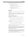
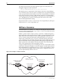
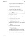
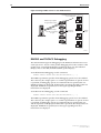
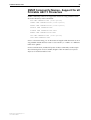
A simple example of the process for limiting the amount of bandwidth used by
traffic from a particular IP address is shown in Figure 5. In the domain shown,
this bandwidth limit is supplied by the class of service represented by a DSCP
value of 40. In the next DiffServ domain, this traffic is assigned to the class of
service represented by a DSCP value of 3.
Figure 5: An example of a DiffServ domain.
Classify by source IP address
Mark with DSCP=40
Limit bandwidth
Non-DiffServ
traffic
DiffServ Domain
Classify by DSCP=40
Limit bandwidth
Classify by DSCP=40
Limit bandwidth
Re-mark to DSCP=3
Next DiffServ
domain
QoS3
AT-8900 Series Software Release 2.6.1
C613-10391-00 REV A
Software Release 2.6.1
29
To use the QoS tool set to configure a DiffServ domain:
1.
Classify the packets coming into the domain at edge switches, according to
the required characteristics. For available options, see the CREATE
CLASSIFIER command in the Generic Packet Classifier chapter, AT-8900
Series Software Reference.
Assign the classifiers to flow groups and the flow groups to traffic classes,
with a different traffic class for each DiffServ code point grouping within
the DiffServ domain.
Give each traffic class the priority, RED curve and/or bandwidth limiting
controls that are required for that type of packet within this part of the
domain.
Assign a DSCP value to each traffic class, to be written into the TOS field of
the packet header, using the MARKVALUE parameter of the CREATE
TRAFFIC CLASS or SET TRAFFIC CLASS commands.
2.
On switches and routers within the DiffServe domain, classify packets
according to the DSCP values that were assigned to traffic classes on the
edge switches.
Assign the classifiers to flow groups and the flow groups to traffic classes,
with a different traffic class for each DiffServ code point grouping within
the DiffServ domain.
Give each traffic class the priority, RED curve and/or bandwidth limiting
controls that are required for that type of packet within this part of the
domain. These QoS controls need not be the same for each switch.
3.
As packets leave the DiffServ domain, classify them according to the DSCP
values.
Assign the classifiers to flow groups and the flow groups to traffic classes,
with a different traffic class for each DiffServ code point grouping within
the DiffServ domain.
Give each traffic class the priority, RED curve and/or bandwidth limiting
controls required for transmission of that type of packet to its next
destination, in accordance with any Service Level Agreement (SLA) with
the providers of that destination.
If necessary, assign a different DSCP value to each traffic class, to be written
into the TOS field of the packet header, to match the DSCP or TOS priority
values of the destination network.
AT-8900 Series Software Release 2.6.1
C613-10391-00 REV A
30
Release Note
How to Enable DiffServ QoS Functionality on the
switch
The switch will process traffic for Quality Of Service according to the
guidelines provided by RFC2475 (An Architecture for Differentiated Services).
DSCP-based classification, marking and meter-based remarking are supported.
To enable DiffServ QoS functionality on the switch follow these steps:
1.
Create classifiers, flow groups, traffic classes and policies
To create the QoS elements and specify the functionality of these elements,
use the following commands:
CREATE CLASSIFIER
CREATE QOS FLOWGROUP=flowgroup-list [other-parameters]
CREATE QOS TRAFFICCLASS=id-list [other-parameters]
CREATE QOS POLICY=id-list [other-parameters]
The default traffic class values are specified with the CREATE QOS
POLICY command.
2.
Set the properties of the DSCP-based QoS marking tables
If premarking or remarking functionality is specified in either the CREATE
QOS FLOWGROUP, CREATE QOS TRAFFICCLASS, or CREATE QOS
POLICY commands, you need to set the properties of the DSCP-based QoS
marking tables.
To set the properties of the DSCP-based QoS marking tables, use the
command:
SET QOS DSCPMAP [={PREMARKING|REMARKING}] DSCP=dscp-list
BWCLASS=bwclass-list [NEWDSCP=dscp-value]
[NEWBWCLASS=bandwidth-class] [NEWQUEUE=queuenumber]
[NEWPRIORITY=vlan-priority]
3. Add classifiers to a flow group, add flow groups to a traffic class, and add
traffic classes to a policy
To logically link QoS elements, use the following commands:
ADD QOS FLOWGROUP=flowgroup-id CLASSIFIER=classifier-list
ADD QOS TRAFFICCLASS=tcid FLOWGROUP=flowgroup-list
ADD QOS POLICY=id TRAFFICCLASS=tcid-list
Note that if premarking is specified with the CREATE QOS FLOWGROUP
command, this overrides premarking specified with the CREATE QOS
TRAFFICCLASS command.
4.
For congestion control set the RED curve values
To create RED curve sets and then set the properties of these RED curve
sets, use the following commands:
CREATE QOS RED=red-id [DESCRIPTION=description]
SET QOS RED=red-id [AVERAGING=averaging-factor]
[DESCRIPTION=description] [QUEUE=queue-list]
[START1=start] [STOP1=stop] [DROP1=probability]
[START2=start] [STOP2=stop] [DROP2=probability]
[START3=start] [STOP3=stop] [DROP3=probability]
A RED curve set is assigned to a port with the SET QOS PORT command.
AT-8900 Series Software Release 2.6.1
C613-10391-00 REV A
Software Release 2.6.1
31
5.
Set the egress queue parameters for a port
To update the parameters for all or specific egress queues on a port, use the
command:
SET QOS PORT={port-list|ALL} EGRESSQUEUE=queue-list
[other-parameters]
This command is used to rate limit and/or force congestion control of
normally uncontested traffic.
6.
Assign the policy to a port
To assign a policy to one or more ports, use the command:
SET QOS PORT={port-list|ALL} [POLICY={id|NONE}]
[DEFAULTQUEUE=queue-number] [FORCEDEFQUEUE={YES|NO}]
[RED={red-id|NONE}]
Note that a port can have only one QoS policy assigned to it.
7.
Set the maximum bandwidth available to a port
By default, the maximum bandwidth is available to a port. To restrict the
maximum bandwidth available to a port, use the command:
SET SWITCH PORT={port-list|ALL}
EGRESSLIMIT={bandwidth|DEFAULT} [other-parameters]
The EGRESSLIMIT parameter specifies the maximum bandwidth available
to the port in multiples of 64 kbps. The EGRESSLIMIT parameter does not
set the exact bandwidth of the port. Rather, the parameter is a
measurement of the rate at which data leaves internal queues before it is
transmitted onto the line. Header and trailer information encapsulated in
the frame are not included in the calculation. The size of the frame impacts
upon the actual data transmission rate that the port can transmit onto the
line. Therefore, the larger the frame size the closer that the actual
percentage of bandwidth on line will get to the bandwidth set.
For more detailed information see the SET SWITCH PORT command in the
Switching chapter of the AT-8900 Series Software Reference for Software
Release 2.6.1.
AT-8900 Series Software Release 2.6.1
C613-10391-00 REV A
32
Release Note
Layer 2 Priority-based QoS
The switch will support Quality Of Service based on Layer 2 parameters for
non-DiffServ compatible traffic. The selection of an egress queue based on the
Layer 2 VLAN Tag Priority Field is supported for frames that are tagged at
ingress, or by selecting a default queue per port for untagged frames. Meter
remarking of Layer 2 priority on the basis of the selected egress queue and
metering bandwidth conformance class is supported. Frames that are untagged
at ingress and do not have their priority set during the marking or remarking
stages, have the egress VLAN Tag Priority value selected from a user definable
mapping of queue values to priority values.
How to Enable Layer 2 QoS Functionality on the
switch
To enable Layer 2 priority-based QoS functionality on the switch follow these
steps:
1.
Set queue based QoS remarking
Queue based remarking is specified by the CREATE QOS TRAFFICCLASS
command.
To specify queue based remarking of VLAN Tag User Priority field, use
either of the commands:
CREATE QOS TRAFFICCLASS=id-list
REMARKING=PRIORITY [other-parameters]
CREATE QOS TRAFFICCLASS=id-list
REMARKING=PRIO+BWCLASS [other-parameters]
The PRIORITY and PRIO+BWCLASS options specify that the currently
assigned queue for frames in this traffic class is used in conjunction with
the temporary bandwidth class to determine the new value of the VLAN
Tag User Priority field from the QUEUE2PRIOMAP table.
The QUEUE2PRIOMAP table specifies the QoS remarking parameters
indexed by the CREATE QOS TRAFFICCLASS command.
To set the properties of the QUEUE2PRIOMAP table, use the command:
SET QOS QUEUE2PRIOMAP=queue-list BWCLASS=bwclasslist
NEWPRIORITY=vlan-priority
The BWCLASS parameter specifies the value(s) of bandwidth class for
which the priority value should be updated.
The NEWPRIORITY parameter specifies the new VLAN Tag User Priority
to use for each frame, selected by the frames internal queue and bandwidth
class indexes.
To specify queue based remarking of the default traffic class, use either of
the commands:
CREATE QOS POLICY=id-list DTCREMARKING=PRIORITY
[other-parameters]
CREATE QOS POLICY=id-list DTCREMARKING=PRIO+BWCLASS
[other-parameters]
Note that the steps for assigning a traffic class to a policy, and a policy to a
port, are not described here. These steps are described in “How to Enable
DiffServ QoS Functionality on the switch” on page 30.
AT-8900 Series Software Release 2.6.1
C613-10391-00 REV A
Software Release 2.6.1
33
2.
Set the initial queue assignment for tagged frames
To set the mapping of incoming VLAN Tag User Priorities to the internal
service queues for ingressing packets that include a VLAN tag header, use
the command:
SET QOS PRIO2QUEUEMAP=p0,p1,p2,p3,p4,p5,p6,p7
The integers p0 to p7 indicate the queue priority corresponding to an
incoming VLAN Tag User Priority. All eight values are required. The first
value, p0, represents the queue priority corresponding to an incoming
VLAN Tag User Priority of 0 (zero), and similarly values p1 to p7 represent
the queue priority corresponding to an incoming VLAN Tag User Priority
of 1 to 7. The default values are 2,0,1,3,4,5,6,7 as recommended in IEEE
802.1q (1998) section 8.7.3.
3.
Set the default queue for untagged frames ingressing a specified port
To set the default queue for untagged frames ingressing a specified port or
ports and which have no VLAN Tag User Priority value, use the command:
SET QOS PORT={port-list|ALL} DEFAULTQUEUE=queue-number
[other-parameters]
If the default queue is not reassigned by premarking and/or remarking,
this will be the egress queue number.
4.
Specify that all frames are forced to the default queue
To specify that all frames ingressing a specified port or ports are forced to
the default queue, regardless of whether they are tagged or untagged, use
the command:
SET QOS PORT={port-list|ALL} FORCEDEFQUEUE={YES|NO}
[other-parameters]
5.
Set the VLAN Tag Priority field assigned at egress
To set the VLAN Tag Priority field assigned at egress for frames that were
untagged at ingress, i.e frames that had a queue assigned by the SET QOS
PORT DEFAULTQUEUE command, use the command:
SET QOS DEFAULTPRIORITY=q0,q1,q2,q3,q4,q5,q6,q7
The integers p0 to p7 represent the VLAN Tag User Priority corresponding
to an to an internal Class of Service queue. All eight values are required.
The first value, q0, represents the VLAN Tag User Priority corresponding
to an internal Class of Service queue of 0 (zero), and similarly values q1 to
q7 represent the VLAN Tag User Priority corresponding to an internal
Class of Service queue of 1 to 7. The default set of values is 1,2,0,3,4,5,6,7.
This is the reverse of the default PRIO2QUEUEMAP setting.
Only frames that do not have a User Priority value assigned by any other
QoS mechanism have a value assigned this way.
AT-8900 Series Software Release 2.6.1
C613-10391-00 REV A
34
Release Note
SET QOS QUEUE2PRIOMAP command
The command syntax for the SET QOS QUEUE2PRIOMAP command in the
AT-8900 Series Software Reference is incorrect. The correct command syntax is:
SET QOS QUEUE2PRIOMAP QUEUE=queue-list BWCLASS=bwclasslist
[NEWPRIORITY=vlan-priority]
where:
■
bwclasslist is either an integer in the range 1 to 3; a range of integers
(specified as 1-3) or a comma separated list of integers and/or ranges,
without spaces.
■
queue-list is either an integer in the range 0 to 7; a range of integers
(specified as 0-3) or a comma separated list of integers and/or ranges,
without spaces.
■
vlan-priority is an integer in the range 0 to 7.
This command sets the queue-based QOS remarking parameters. For each
queue value, the outgoing VLAN Tag User Priority may be set to one of three
values, depending on its bandwidth class. Queue based remarking is selected
by setting the Traffic Class REMARKING parameter to PRIORITY or
PRIO+BWCLASS.
The QUEUE parameter specifies which queue(s) to update with the specified
settings. A value must be supplied as there is no default.
The BWCLASS parameter specifies the value(s) of bandwidth class for which
the priority value should be updated. If BWCLASS is not specified, the settings
will apply for all values of bandwidth class on the specified queue(s),
otherwise a value must be supplied.
The NEWPRIORITY parameter specifies the new VLAN Tag User Priority to
use for each frame selected by its internal queue and bandwidth class indexes.
The preset value for NEWPRIORITY is zero. If NEWPRIORITY is specified, a
value must be supplied as there is no default.
Autonegotiation of port speed and
duplex mode
For the 10/100Base-T ports, if one of 10MHALF, 10MFULL, 100MHALF, or
100MFULL is specified then autonegotiation is disabled and the interface is
forced to operate at the specified speed and duplex mode, regardless of
whether the link partner is capable of working at that speed.
The SFP uplink ports are fixed at full-duplex and at a speed of 1 Gbps.
Switch ports will autonegotiate by default when they are connected to a new
device. To change this setting, use the command:
SET SWITCH PORT={port-list|ALL} SPEED={AUTONEGOTIATE|10MHALF|
10MFULL|10MHAUTO|10MFAUTO|100MHALF|100MFULL|100MHAUTO|
100MFAUTO|1000MFULL} [other-parameters]
AT-8900 Series Software Release 2.6.1
C613-10391-00 REV A
Software Release 2.6.1
35
Auto MDI/MDI-X
MDI and MDI-X are Medium Dependent Interface port configurations for
copper based interfaces. An MDI interface at one end and an MDI-X (MDI
crossover) interface at the other end of a straight-through cable ensures the
correct correspondence between the transmitting and receiving interface cable
pairs. If both ends have MDI interfaces, or both ends have MDI-X interfaces, a
crossover cable is required. “Polarity” refers to whether a port operates as MDI
or MDI-X.
The auto MDI/MDI-X feature enables a switch port to detect whether it needs
to have MDI or MDI-X polarity for a link. This means that straight-through (or
crossover) cables can be used to connect these ports, whatever the MDI or
MDI-X polarity of the other end. Some switch ports perform auto MDI/MDI-X
by default as part of port autonegotiation. On some ports you can disable this
auto MDI/MDI-X feature so that the ports are configured with a fixed MDI or
MDI-X polarity. To disable auto MDI/MDI-X, use the command:
DISABLE SWITCH PORT={port-list|ALL} AUTOMDI
When auto MDI/MDI-X is disabled, the switch port polarity is set to the
default, MDI-X. To modify the fixed polarity, use the command:
SET SWITCH PORT={port-list|ALL} POLARITY={MDI|MDIX}
[other-parameters]
You can use the commands above to configure the base ports. Copper SFP
transceivers plugged into the SFP uplink sockets are auto MDI/MDI-X, and
cannot be set to a fixed polarity. Fibre ports do not have MDI/MDI-X polarity.
Port trunking
Port trunking, also known as port bundling or link aggregation, allows a
number of ports to be configured to join together to make a single logical
connection of higher bandwidth. This can be used where a higher performance
link is required and makes links even more reliable.
The switch supports up to 7 trunking groups, with to 4 ports per trunk group.
Ports in the trunk group do not have to be contiguous.
The AT-8900 Series Software Reference for Software Release 2.6.1 incorrectly
states that the maximum number of trunking groups supported is 31.
AT-8900 Series Software Release 2.6.1
C613-10391-00 REV A
36
Release Note
Broadcast Storm Protection
The storm control feature allows you to set limits on the reception rate of:
■
broadcast and multicast packets on a per port basis, i.e one limit per port
■
destination lookup packets for all ports on the switch, i.e one limit for the
switch
The switch hardware counts separately the number of broadcast, multicast,
and destination lookup failure packets in bytes received per second, and
discards packets once the byte limit is reached.
The minimum rate is 100 Kbytes per second, increasing in steps of 100 Kbytes
per second to the maximum rate of 95300 Kbytes per second.
Broadcast and multicast rate limiting
You can set one port limit for broadcast and multicast packet limiting.
Therefore, the maximum reception rate limit is the same for both broadcast and
multicast packets on a port and independent limits for broadcast and multicast
packets cannot be set.
On a per port basis, you can enable:
■
broadcast rate limiting
■
broadcast and multicast rate limiting
It is not possible to have multicast rate limiting enabled without having broadcast
limiting enabled.
If multicast rate limiting is enabled, then it is active for all ports that:
■
already have broadcast limiting set and enabled
■
subsequently have broadcast limiting enabled after multicast limiting is
enabled
Multicast rate limiting is either on for all ports that have broadcast limiting
enabled, or off for all ports.
To set broadcast storm control and the reception rate limit for a port or ports,
use the command:
SET SWITCH PORT=port-list BCLIMIT={NONE|limit}
[other-parameters]
where:
■
limit is a decimal number between 0 and 95300, in Kbytes per second
To enable and disable the multicast storm control, which works in conjunction
with broadcast limiting, use the command:
ENABLE SWITCH MCLIMITING
DISABLE SWITCH MCLIMITING
To display whether broadcast and multicast storm control is enabled or
disabled for a port, or all ports, use the command:
SHOW SWITCH PORT=port-list
AT-8900 Series Software Release 2.6.1
C613-10391-00 REV A
Software Release 2.6.1
37
Destination lookup failure packets
Destination lookup failure packets have a Layer 2 destination address that the
switch has not learnt and are in effect multicast packets. The switch does not
know where to forward the packets, so the packets are broadcast to all ports on
the switch. You can limit the rate at which destination lookup failure packets
are received.
To set destination lookup failure rate limiting on the switch, use the command:
SET SWITCH DLFLIMIT={NONE|limit}
where:
■
limit is a decimal number between 0 and 95300, in Kbytes per second
To display whether destination lookup failure storm control is enabled or
disabled the switch, use the command:
SHOW SWITCH
VLAN Membership of Untagged Packets
The switch can determine the VLAN that incoming untagged packets belong
to, on the basis of:
■
IP subnet: The subnet that the packet came from, for IP packets
■
Protocol: The protocol of the packet
■
Port: The port the packet arrives to
VLANs are multi-typed and can have all 3 classification rules in any VLAN
created. The VLAN associations available with this classification and their
precedence are shown in Table 9.
Table 9: VLAN association and precedence.
AT-8900 Series Software Release 2.6.1
C613-10391-00 REV A
VLAN classification
VLAN associations available with
this classification
Precedence
Multi-typed
IP Subnet
Highest
Protocol
Medium
Port
Lowest
38
Release Note
Creating VLANs
To briefly summarise the process of creating a VLAN:
1.
Create the VLAN and specify its classification, one of IP subnet, protocol, or
port.
2.
Add tagged ports to the VLAN, if required.
3.
Create associations to associate subnets and protocols with the VLAN if
untagged ports are required. These associations determine the VLAN that
incoming untagged packets belong to.
4.
Add untagged ports to the associations.
Creating the VLAN and Specifying the VLAN
Classification
Up to 4094 VLANs can be created, with VIDs ranging from 2 to 4094. VLANs
do not have to be numbered consecutively. Creating a VLAN involves (in a
single CREATE VLAN command) giving the VLAN a name, specifying a VID
for the VLAN, and specifying its classification. A particular subnet or protocol
can be associated with the VLAN at the same time, or later with the ADD
VLAN command.
To create a IP subnet based VLAN, use the command:
CREATE VLAN=vlan-name VID=2..4094 [SUBNET=ipadd] [MASK=ipadd]
To create a protocol based VLAN, use the command:
CREATE VLAN=vlan-name VID=2..4094 [PROTOCOL=protocol-type]
To create a port based VLAN, use the command:
CREATE VLAN=vlan-name VID=2..4094
When any VLAN is created, an empty port association is automatically created.
This allows untagged ports to be added to the VLAN without associating them
with a subnet or protocol.
The Default VLAN
The default VLAN is created automatically when the switch is first powered
up, and all the ports on the switch are added its port association.
The initial configuration of the default VLAN is unclassified. The VLAN can be
given a classification type of IP subnet or protocol by adding an association to
it, using the commands:
ADD VLAN=1 SUBNET=ipadd [MASK=ipadd]
ADD VLAN=1 PROTOCOL=protocol-type
If the default VLAN is the first VLAN on the switch to be classified, the
classification it is given limits the classification of any other VLANs created, as
described in Table 10. If another VLAN is created before the default VLAN is
given a classification type, this sets the default VLAN’s classification.
AT-8900 Series Software Release 2.6.1
C613-10391-00 REV A
Software Release 2.6.1
39
Table 10: Types of VLAN available with each VLAN classification.
VLAN classification
Types of VLAN available with this
classification
IP subnet-based
IP Subnet
Protocol
Port
Protocol-based
Protocol
Port
Port-based
Port
Protected VLANs
The Protected VLAN feature prevents the members of a specified group of
ports from communicating with each other, yet still allows these members to
access another network. Ports on a switch that has Protected VLAN
functionality enabled are given one of two states, either private (protected) or
public. Private ports cannot talk to other private ports but can talk to public
ports. Public ports can talk to both private or public ports.
All traffic received on a given port in a Protected VLAN is sent to a predefined
defined uplink port, and only that uplink port, regardless of VLAN ID or MAC
Destination address. Layer 2 traffic between ports that are members of a
Protected VLAN is blocked. Traffic can be Layer 3 switched to another VLAN.
To prevent Layer 3 Routing between ports in a Protected VLAN add a Layer 3
filter. The Protected VLAN feature also allows all members of a Protected
VLAN to be in the same subnet.
A typical application is a hotel installation where each room has a port that can
access the Internet. In this situation it is undesirable to allow communication
between rooms.
To enable Protected VLAN functionality on the switch, use the command:
ENABLE VLAN PORTPROTECTED
To create a Protected VLAN, use the command:
CREATE VLAN=vlan-name VID=2..4094 PORTPROTECTED
The PROTECTED parameter specifies that the VLAN is a Protected VLAN.
To add ports to a Protected VLAN, use the command:
ADD VLAN={vlan-name|1..4094} PORT={port-list}
[GROUP=group-number|uplink-number|UPLINK]
[UPLINK=uplink-number] [other-parameters]
The GROUP parameter specifies that the ports are members of a Protected
VLAN and are known as protected ports. Each group is unique and is
identified by its group number. All traffic received on a protected port is sent to
a predefined uplink port, or a group of uplink ports, called an uplink group.
AT-8900 Series Software Release 2.6.1
C613-10391-00 REV A
40
Release Note
To delete ports from a Protected VLAN, use the command:
DELETE VLAN={vlan-name|1..4094} PORT={port-list|ALL}
[GROUP=group-number|uplink-number]
To disable Protected VLAN functionality on the switch, use the command:
DISABLE VLAN PORTPROTECTED
Multiple Spanning Trees and STP
Interaction with VLANs
If creating multiple STPs in a network, a port in a switch can belong to multiple
STPs if the port is a member of more than one VLAN
The AT-8900 Series Software Reference for Software Release 2.6.1 incorrectly
states that if creating multiple STPs in a network, a port in a switch can belong
to one STP only and that if a port is a member of multiple VLANs, then all
those VLANs must belong to the same STP.
Overlapping VLANs Belonging to
Multiple Spanning Tree Instances
The switch support the situation where a port is contained in more than one
Spanning Tree instance when the port is a member of more than one VLAN
and those VLANs belong to different STPs (See Figure 6).
The number of STPs that can be configured is 256.
Figure 6: Port membership of VLANs which belong to different spanning tree instances
STP A
STP B
VLAN 1
VLAN 2
VLAN 3
Port 1
Port 2
Port 3
Port 2 is a member of multiple Spanning Tree Instances (STP A and STP B) because it is a member of
multiple VLANs (VLAN 2 and VLAN 3).
SWITCH12
AT-8900 Series Software Release 2.6.1
C613-10391-00 REV A
Software Release 2.6.1
41
The Ingress and Egress Rules for Layer 2
Switching
Two components of the Layer 2 switching process are the Ingress and Egress
Rules. The Ingress Rules admit or discard frames based on their VLAN
tagging. The Egress Rules determine for each frame whether VLAN tags are
included in the Ethernet frames that are transmitted.
The Ingress Rules
All frames, tagged and untagged, received by a VLAN-aware switch must be
associated with a VLAN. Each received frame is mapped to exactly one VLAN.
If an incoming frame is tagged with a valid VLAN Identifier (VID) then that
VID is used. If an incoming frame is untagged, or is priority tagged (a tagged
frame with a VID of all zeros), then the switch uses internal VLAN association
rules to determine the VLAN it belongs too. The default setting for the Ingress
Rules is to Admit All Frames.
The possible association rules, in order of precedence, are:
■
IP subnet/IPX network classification
■
protocol classification
■
port classification
The switch supports a subset of these VLAN association rules at any one time.
The possible subsets used are:
■
IP subnet, protocol and port classification
■
protocol and port classification
■
port classification
The Egress Rules
Once the Forwarding Process has determined which ports and transmission
queues to forward a frame from, the Egress Rules for each port determine
whether or not the outgoing frame is VLAN-tagged with its numerical VLAN
Identifier (VID).
A port must belong to a VLAN at all times unless the port has been set as the
mirror port for the switch.
A port can transmit VLAN-tagged frames for any VLAN to which the port
belongs. A port can transmit untagged frames for any VLAN for which the
port is configured, e.g. IP subnet-based or protocol-based, unless prevented by
the port-based VLAN egress rules. A port that belongs to a port-based VLAN
can transmit untagged packets for only one VLAN.
AT-8900 Series Software Release 2.6.1
C613-10391-00 REV A
42
Release Note
Classifier-Based Packet Filters
You can configure the switch hardware through entries in the Generic Packet
Classifier, or Classifier, to copy, drop, forward, and associate QOS attributes to
packets that match specified criteria.
Every packet passing through the switch is matched against a series of
classification tables by the Classifier. Classify packets according to:
■
Packet type
■
Layer 3 protocol
■
Source/destination IP address
■
Destination IPX address
■
Layer 4 protocol (for example: TCP/UDP/Socket number)
■
Layer 4 source/destination ports
■
Source/Destination MAC address
■
Source VLAN
Classifier-based packet filters are numbered in the range 1 to 1024. The number
of packet filters supported by the switch is determined by the amount of
available space in the packet classification tables.
To add packet filters to the switch, use the command:
ADD SWITCH HWFILTER=filter-id CLASSIFIER=rule-id
ACTION={COPY|DISCARD|FORWARD|COPY,DISCARD}
To delete one or more packet filters from the switch, use the command:
DELETE SWITCH HWFILTER=filter-idlist
To delete all classifiers from a single packet filter, use the command:
DELETE SWITCH HWFILTER=filter-id CLASSIFIER=ALL
To show packet filters, use the command:
SHOW SWITCH HWFILTER[=filter-idlist]
Dynamic Port Security
Dynamic Port Security enables dynamic MAC address learning. If a MAC
address is unused for a period of time, it will be aged from the database of
currently accepted MAC addresses. This enables new MAC addresses to be
learned.
The RELEARN parameter defaults to OFF. In this case static MAC address
learning will be used. This means that MAC addresses once learned, cannot be
unlearned.
SHOW SWITCH PORT={port-list|ALL} INTRUSION
A switch port can be manually locked before it reaches the learning limit, by
using the command:
ACTIVATE SWITCH PORT={port-list|ALL} LOCK
AT-8900 Series Software Release 2.6.1
C613-10391-00 REV A
Software Release 2.6.1
43
Addresses can be manually added to a port locked list up to a total of 256 MAC
addresses, and the learning limit can be extended to accommodate them, by
using the command:
ADD SWITCH FILTER ACTION={FORWARD|DISCARD}
DESTADDRESS=macadd PORT=port [ENTRY=entry] [LEARN]
[VLAN={vlan-name|1..4094}]
Learned addresses on locked ports can be saved as part of the switch
configuration, so that they will be part of the configuration after a power cycle,
using the command:
CREATE CONFIG=filename
If the configuration is not saved when there is a locked list for a port, the
learning process begins again after the switch is restarted. Addresses learned
through dynamic MAC learning will not be added to the configuration.
MAC Address Logging
MAC Address Logging allows the user to initiate logging of the MAC
addresses of equipment connected to the switch LAN interfaces, and which
access the WAN interface.
This provides an auditing trail in the event of anyone hacking into the system.
If NAT is used, the layer two MAC address of the equipment needs to be
logged in addition to the IP address.
You can enable and disable MAC address logging using the commands:
ENABLE IP ARP LOG
DISABLE IP ARP LOG
Changes to Proxy ARP Defaults
Proxy ARP is defined in RFC 1027. It allows hosts which do not support
routing (i.e. they have no knowledge of the network structure) to determine the
physical addresses of hosts on other networks. The switch intercepts ARP
broadcast packets and substitutes its own physical address for that of the
remote host. This only occurs if the switch has the best route to the remote host.
By responding to the ARP request the switch ensures that all subsequent
packets from the local host will be directed to the switch’s physical address and
it can then forward these to the remote host.
Proxy ARP is disabled by default. To enable or disable proxy ARP on an IP
interface, use one of the commands:
ADD IP INTERFACE=interface IPADDRESS={ipadd|DHCP}
PROXYARP={FALSE|NO|OFF|ON|TRUE|YES} [other-options...]
SET IP INTERFACE=interface PROXYARP={FALSE|NO|OFF|ON|TRUE|
YES} [other-options...]
To display details of the interfaces assigned to the IP module, including
whether or not Proxy ARP is enabled on each interface, use the command:
AT-8900 Series Software Release 2.6.1
C613-10391-00 REV A
44
Release Note
SHOW IP INTERFACE
For more information, see the Internet Protocol (IP) chapter of the AT-8900 Series
Software Reference for Software Release 2.6.1.
Dynamic Host Control Protocol for IPv6
The Dynamic Host Configuration Protocol for IPv6 (DHCP6) is used to
delegate IPv6 prefixes, and to allocate IPv6 addresses. It offers stateful address
autoconfiguration, and complements the stateless address autoconfiguration
described in RFC 2462 “IPv6 Stateless Address Autoconfiguration”. DHCP is
particularly useful for ISPs to allocate IPv6 prefixes to customer sites. The
creation and allocation of complete IPv6 addresses is then performed by IPv6
stateless address autoconfiguration.
The switch can be configured as a DHCP6 server or client. As a DHCP6 server,
it can:
■
delegate prefixes to IPv6 subnets. Prefixes allow a subnet to be addressed,
rather than a single node. Like IPv4 addresses, a proportion of the leftmost
bits of the IPv6 address can be used to indicate the subnet. IPv6 addresses
can then be allocated by stateless address autoconfiguration, by manual
configuration, or by using DHCP6.
■
assign normal and temporary IPv6 addresses to devices. An IPv6 address
is a hexadecimal string, made up from eight pairs of octets separated by
colons, for example 3ffe:2::0:1. Normal addresses are renewed by the server
for as long as the device requires an address. Temporary addresses are
assigned for a limited time (lease time) and are usually allocated for
privacy reasons, as outlined in RFC 3041 “Privacy Extensions for Stateless
Address Autoconfiguration in IPv6”.
As a DHCP6 client, the switch can request an IPv6 address or a prefix from a
DHCP6 server.
Configuring DHCP6 Servers
A DHCP6 server can delegate prefixes and/or allocate IPv6 addresses.
To configure the switch as a DHCP6 server:
1.
Enable IPv6 and create an IPv6 interface on the server, using the commands:
ENABLE IPV6
CREATE IPV6 INTERFACE=interface
2.
Enable the DHCP6 module on the server, using the command:
ENABLE DHCP6
3.
Create a DHCP6 policy on the server
Create a policy to contain the configuration information that will be given
to a requesting IPv6 host, and give it a name, using the command:
CREATE DHCP6 POLICY=policy [INHERIT=name]
AT-8900 Series Software Release 2.6.1
C613-10391-00 REV A
Software Release 2.6.1
45
4.
Configure the server to delegate a prefix or range of prefixes by assigning
the IPv6 prefixes to the policy and specifying a type of PD, using the
command:
CREATE DHCP6 RANGE=range POLICY=policy
IP=ipv6address/prefix-ipv6address/prefix TYPE=PD
Configure the server to delegate a range of addresses, by assigning a range
of IPv6 addresses to the policy, using the command:
CREATE DHCP6 RANGE=range POLICY=policy
IP=ipv6address/prefix[-ipv6address/prefix]
[TYPE={NORMAL|TEMP}]
5.
If required, add static entries to the range, configure authentication, and
add any other required configuration settings to the policy.
6.
Link the policy to the required IPv6 interface, using the command:
ADD DHCP6 INTERFACE=interface POLICY=name
Configuring DHCP6 Clients
A DHCP6 client can request an IPv6 address for one or more of its interfaces. It
can also request a DHCP6 prefix over its interface to the DHCP6 server, and
then apply that prefix to other interfaces.
To configure the switch as a DHCP6 client that will request an IPv6 address
from a DHCP6 server:
1.
Enable the IPv6 module, using the command:
ENABLE IPV6
2.
Create the required interface, using the command:
CREATE IPV6 INTERFACE=interface
3.
Configure the interface to request its IP address from DHCP6, using the
command:
ADD IPV6 INTERFACE=interface IP=DHCP
To configure the switch as a DHCP6 client that will request a prefix from a
DHCP6 server, and then apply the prefix to other interfaces:
1.
Enable the IPv6 module, using the command:
ENABLE IPV6
2.
Create the required interface, using the command:
CREATE IPV6 INTERFACE=interface
3.
Configure that interface to request a prefix and apply it to another interface
or interfaces, using the command:
ADD IPV6 INTERFACE=interface IP=PD
APPINT=app-interface[,...]
The INTERFACE parameter specifies the interface that will request the
prefix from a server. The APPINT parameter specifies the interface or
comma-separated list of interfaces that the switch will apply the received
prefix to.
4.
Turn on router advertisements to allow the switch to advertise its prefixes
to the clients for stateless address autoconfiguration, using the command:
ENABLE IPV6 ADVERTISE
AT-8900 Series Software Release 2.6.1
C613-10391-00 REV A
46
Release Note
For background information, examples, more information about these
commands, and information about other optional settings for DHCP6, see the
Dynamic Host Configuration Protocol for IPv6 (DHCP6) chapter of the AT-8900
Series Software Reference for Software Release 2.6.1.
For general information about configuring IPv6 interfaces, see the Internet
Protocol version 6 chapter of the AT-8900 Series Software Reference for Software
Release 2.6.1.
Setting Preference of IPv6 Dynamic
Routes
This enhancement enables you to configure your own preference for the routes
learned from the dynamic IPv6 routing protocol RIPv6.
To specify the preference for RIPv6, use the command:
SET IPV6 ROUTE PREFERENCE={DEFAULT|1..65535} PROTOCOL=RIP
When more than one route in the route table matches the destination address in
an IPv6 packet, the route with the lowest preference value will be used to route
the packet. If two or more candidate routes have the same preference, the route
with the longest prefix will be used. All existing dynamically learned routes in
the routing table, and new routes added subsequently, will be updated with
the specified preference value. When multiple dynamic routing protocols
become available for IPv6, this enhancement will give you greater control over
routing decisions.
If you specify a preference of DEFAULT, the preference will revert to the
default value for this protocol type.
To display information about the current IPv6 route table preferences for RIP
(Figure 7), use the command:
SHOW IPV6 ROUTE PREFERENCE
Figure 7: Example output from the SHOW IPV6 ROUTE PREFERENCE command.
IPv6 Route Preference
---------------------------------------------------------Protocol
Preference
--------------------------------------------------------RIP ............................... 100 (default)
----------------------------------------------------------
For more information about IPv6 and RIPv6, see the Internet Protocol version 6
chapter of the AT-8900 Series Software Reference for Software Release 2.6.1.
AT-8900 Series Software Release 2.6.1
C613-10391-00 REV A
Software Release 2.6.1
47
Adding an IPv6 Host with a Link-Local IP
Address
Software Release 2.6.1 enables you to specify a host name to telnet to an IPv6
link-local address. It does this by allowing you to specify the interface as well
as the address. Telneting to a link-local address requires interface information
as well as the address, because a single link-local address can belong to several
interfaces.
To specify a host name, use the command:
ADD IPV6 HOST=name IPADDRESS=ipv6add [INTERFACE=interface]
When the IP address is a link-local address, the INTERFACE parameter lets
you specify the interface out which the Telnet request is sent, as well as the
address. This interface is the interface, on the switch from which the Telnet
request originates, that is connected to the required destination interface
(Figure 8).
Figure 8: The outgoing interface to specify when Pinging or Telneting to an IPv6
link-local address.
vlan1
fe80::7c27
vlan2
outgoing
interface
fe80::7c27
Telnet or Ping
IPV63_S
Network or Broadcast Addresses Not
Issued by DHCP
The DHCP server will no longer issue network or broadcast addresses to
clients.If a range is created to include such addresses, those addresses will be
excluded from the pool of addresses available to clients.
For more information about DHCP, see the Dynamic Host Configuration Protocol
chapter of the AT-8900 Series Software Reference for Software Release 2.6.1.
AT-8900 Series Software Release 2.6.1
C613-10391-00 REV A
48
Release Note
DHCP Compliance with RFC 2131
DHCP policies are no longer limited to a minimum lease time of 3600 seconds.
This complies with RFC 2131, “Dynamic Host Configuration Protocol”.
To create a DHCP policy, use the command:
CREATE DHCP POLICY=name LEASETIME={lease-time|INFINITY}
[INHERIT=name]
where lease-time is a time in seconds.
Routers or switches that comply with RFC 1541 but not with RFC 2131 may not be able
to accept a lease time of less than 3600 seconds.
For more information about DHCP, see the Dynamic Host Configuration Protocol
chapter of the AT-8900 Series Software Reference for Software Release 2.6.1.
MIB Support for DHCP Range Exhaustion
Trap
A simple DHCP range exhaustion trap has been added to the ATR enterprise
MIB (atrouter.mib). The trap is triggered when a DHCP request cannot be
satisfied due to range exhaustion. The gateway address and the interface
address of the request are sent as trap variables. The range table shows the
DHCP ranges currently defined on the DHCP server.
The DHCP Group contains objects for managing DHCP. Objects in this group
have the object identifier prefix dhcp ({ modules 70 }). The following objects are
defined:
■
dhcpRangeTable { dhcp 1 } is a table of DHCP ranges. Each entry in the table
gives information about a single DHCP range currently configured on the
switch.
■
dhcpTrapVariable { dhcp 2 } are special variables set up to act as reference
points for variables sent in traps.
For more information see the SNMP MIBs appendix of the AT-8900 Series
Software Reference for Software Release 2.6.1.
Changing User Account Privilege
When you change the privilege level of an existing user, you must now also
specify a password for that user in the command. You can specify either the
user’s existing password or a new one.
To change a user’s privilege level, use the command:
SET USER=login-name PASSWORD=password PRIVILEGE={USER|
MANAGER|SECURITYOFFICER} [other-options...]
For more information about users and privilege levels, see the Operation
chapter of the AT-8900 Series Software Reference for Software Release 2.6.1.
AT-8900 Series Software Release 2.6.1
C613-10391-00 REV A
Software Release 2.6.1
49
User Authentication
The following sections summarise extensions to the switch’s functionality for
authenticating users via authentication servers. For more information about
user privileges, authentication, and the commands outlined in these sections,
see the Operation chapter of the AT-8900 Series Software Reference for Software
Release 2.6.1.
The User Authentication Facility (UAF) supports the following methods of
user authentication: an internal database called the User Authentication
Database, and interrogation of external RADIUS (Remote Authentication Dial
In User Service), TACACS (Terminal Access Controller Access System) or
TACACS+ servers.
The UAF first queries any TACACS+ servers that have been defined. If there
are no defined TACACS+ servers or all the TACACS+ servers return a reject
response, the UAF will query the User Authentication Database. If the supplied
login name and password does not match an entry in the User Authentication
Database, the UAF sends authentication requests to any RADIUS servers that
have been defined. If there are no defined RADIUS servers or all the RADIUS
servers return a reject response, the UAF will send authentication requests to
any TACACS servers that have been defined. If the supplied login name and
password matches an entry in the User Authentication Database, or one of the
defined TACACS+, RADIUS or TACACS servers returns an accept response to
an authentication request, the login is accepted. If the supplied login name and
password does not match an entry in the User Authentication Database, and all
of the defined TACACS+, RADIUS or TACACS servers return reject responses
to authentication requests, the login is rejected. The login is also rejected if
Login is set to No for that user account.
TACACS+
The TACACS+ protocol is a simple TCP-based access control protocol. It
improves on TACACS by:
■
separating the functions of authentication, authorisation and accounting
This release of TACACS+ supports authentication and authorisation services.
■
encrypting all traffic between the Network Access Server (NAS) and the
daemon
■
using TCP as its transport protocol for reliable delivery
■
allowing for authentication exchanges of arbitrary length and content
which will allow any authentication mechanism to be utilised with
TACACS+ clients
■
being extensible to provide for site customisation and future development
features.
TACACS+ allows the authentication, authorisation and accounting services to
be provided independently on separate access servers (TACACS+ servers).
Each service can be tied into its own database or can use the other services
available on that server or on the network.
AT-8900 Series Software Release 2.6.1
C613-10391-00 REV A
50
Release Note
To enable TACACS+, use the command:
ENABLE TACPLUS
To add a TACACS+ server, use the command:
ADD TACPLUS SERVER=ipaddress [KEY=key] [PORT=port]
[SINGLECONNECTION=YES|NO] [TIMEOUT=1...10]
To enable TACACS+ debugging, use the command:
ENABLE TACPLUS DEBUG
Authorisation Services
Authorisation occurs after authentication. It is here that an attribute value (AV)
pair is returned if configured. Attribute Value Pairs are configured on the
TACACS+ server and passed onto the switch. The switch takes the appropriate
action based upon the pair passed to the switch and the value of that pair. If the
TACACS+ server sends an AV pair that is not supported by the switch then
that attribute is ignored.
The following AV Pairs are supported:
■
Timeout
This value specifies the length of time that the session can exist. After this
value has expired, the session will either be disconnected, or have the
privilege of the user reduced. The valid timeout range is 0 to 65535
(minutes).
■
Idletime
If no input or output traffic is received in this time period, the session is
disconnected. The valid idletime range is 0 to 65535 (minutes).
■
Privilege Level
The TACACS+ privilege levels supported are 1, 7, and 15, with the values
mapping to USER, MANAGER, and SECOFF respectively.
S/Key
S/Key is a one-time password system designed to protect networks from attacks
via electronic eavesdropping during user authentication. A user never logs into
a server on the network using the same password more than once. Since a
specific one-time password can only be used to authenticate a user once, even
if the password is intercepted by a malicious user en-route to the
authentication server (via a sniffer), by the time they try to gain access to the
system with it, it will no longer be valid. The S/Key system generates one-time
passwords by applying a one-way MD4 or MD5 hash function to the
concatenation of a user-specified seed and secret password.
S/Key and the newer OTP system are both supported. To set the method of
authentication that the switch will use, and the type of encryption, use the
command:
SET SKEY [METHOD={SKEY|OTP}] [ENCRYPTION={MD4|MD5]
AT-8900 Series Software Release 2.6.1
C613-10391-00 REV A
Software Release 2.6.1
51
To calculate and display (Figure 9) one-time passwords, use the SEQUENCE
and SEED parameters in the command:
SHOW SKEY [SEQUENCE=seq_no SEED=seed_name [NUMBER=value]]
where:
■
seq_no is an integer in the range 1-9999, representing the sequence number
of the last S/Key or OTP password to be generated.
■
seed_name is the 1-16 alphanumeric user-defined string which was used to
initialise the one-time password system on the authentication server.
■
value is an integer in the range 1-99, representing the number of
consecutive S/Key or OTP passwords to generate, finishing at seq_no.
To display the correct one-time passwords, the user must supply their current
sequence number and seed. They will then be asked to enter the password,
which was used when initialising their current sequence of one-time
passwords on the authentication server. The entered password will not be
echoed to the screen. The output will show the sequence of S/Key or OTP onetime passwords to be used for a user’s subsequent login attempts.
Figure 9: Example output from the SHOW SKEY SEQ=n SEED=seed command.
Enter S/KEY initialisation password :
Computing SKEY passwords using MD4....
-----------------------------------------------------------Seq No
One-Time Password
95
IT DOLT ROOM NET GLUT ROWE
96
DARE MOS SARA GOAD MAO LEO
97
GUN TAIL MEND EAT INCH JOHN
98
EARN KID CARE HELD GIRD WINE
99
ADAM WARD DECK PLY EGAN WEED
------------------------------------------------------------
Multiple User Privilege Levels Using RADIUS
This enhancement enables the privilege level of the user to be stored on the
RADIUS server and returned with the user authentication so that the user
database can be centrally administered from the RADIUS server. The user
privilege level affects the commands that a user may execute. Three levels of
privilege for users are supported when the switch is operating in security
mode: User, Manager and Security Officer. The enhancement allows the
authenticated user to log directly into a device at that user’s appropriate
privilege level.
The switch acts as a RADIUS client, sending requests to a RADIUS server
(Figure 10). To enable the RADIUS server to authenticate users and include
their privilege level, set up the server so that it returns an appropriate value in
the Service-Type attribute. For Security Officer privilege, set the attribute to
Administrative (6), for Manager privilege set it to NAS Prompt (7), and for
User privilege set it to any other value or no value.
AT-8900 Series Software Release 2.6.1
C613-10391-00 REV A
52
Release Note
Figure 10: Using a Radius Server for User Authentication.
User dials into Access Server using
Secure Shell (SSH)
RADIUS requests packet
encrypted with secret key
RADIUS accepts
including user privilege,
or rejects
Edge devices/
Access Servers
Remote
Users
RADIUS Server
RADIUS2
RADIUS and TACACS Debugging
This enhancement supports debugging for the RADIUS and TACACS access
control protocols. Access control packet debugging allows the contents of the
packets to be viewed. The debugging commands allow raw (hexadecimal
dumps) and/or decoded (human-readable) packet displays.
To enable RADIUS debugging, use the command:
ENABLE RADIUS DEBUG={ALL|PKT|DECODE|ERROR} [,...]
The DEBUG parameter specifies which debugging options are to be enabled.
The value may be a single option or a comma-separated list of options. If ALL
is specified, all debugging options are enabled. If PKT is specified, the raw
RADIUS packets are displayed. If DECODE is specified, decoded packets are
displayed. If ERROR is specified, error messages regarding RADIUS
transactions are displayed.
To enable TACACS debugging, use the command:
ENABLE TACACS DEBUG={ALL|PKT|DECODE|ERROR} [,...]
The DEBUG parameter specifies which debugging options are to be enabled.
The value may be a single option or a comma-separated list of options. If ALL
is specified, all debugging options are enabled. If PKT is specified, the raw
TACACS packets are displayed. If DECODE is specified, decoded packets are
displayed. If ERROR is specified, error messages regarding TACACS
transactions are displayd.
AT-8900 Series Software Release 2.6.1
C613-10391-00 REV A
Software Release 2.6.1
53
Ping Polling of Device Reachability
This enhancement enables the switch to regularly check whether or not it can
reach a device. It also enables a trigger to activate on the switch when the
device becomes unreachable. While the device is unreachable, the switch
continues to monitor the device’s reachability, and another trigger can be set to
activate when the device becomes available again. For example, the first
trigger’s script could open and configure an alternative link if the device at the
other end of a preferred link became unavailable. The second trigger’s script
would automatically return traffic to the preferred link as soon as it was
available again.
To determine the device’s reachability, the switch will regularly send ICMP
Echo Request packets (“pings”) to the device. As long as the switch receives
ping responses from the device, it considers the device to be reachable. After
the switch has not received a reply to a set number of ICMP Echo Requests, it
considers the device to be unreachable. It continues to try to ping the device, at
an increased rate. After it receives a set number of responses, it considers the
device to be reachable again.
Configuring the switch to determine a device’s reachability and respond to
changes in reachability involves the following steps:
■
Create a polling instance, to periodically ping the device
■
Create scripts to run when the device becomes unreachable and when it
becomes reachable again
■
Configure triggers to run these scripts.
To create a polling instance, use the command:
ADD PING POLL=poll-id IPADDRESS={ipadd|ipv6add[%interface]}
[CRITICALINTERVAL=1..65535]
[DESCRIPTION=poll-description] [FAILCOUNT=1..100]
[LENGTH=4..1500] [NORMALINTERVAL=1..65535]
[SAMPLESIZE=1..100] [SIPADDRESS={ipadd|ipv6add}]
[TIMEOUT=1..30] [UPCOUNT=1..100]
where poll-id is a number from 1 to 100, and identifies the polling instance in
the trigger commands and in other PING POLL commands. The switch can
poll up to 100 IP addresses at once.
The NORMALINTERVAL parameter specifies the time period between pings
when the device is reachable. By default, this is set to 30 seconds. The
CRITICALINTERVAL parameter specifies the time period between pings
when the switch has not received a reply to at least one ping and when the
device is unreachable. The default is 1 second. The CRITICALINTERVAL
enables the switch to quickly observe changes in the state of the device, and
should be set to a much lower value than the NORMALINTERVAL.
The number of pings that the switch will examine to consider a change in state
is controlled by three parameters: FAILCOUNT, SAMPLESIZE, and
UPCOUNT. The FAILCOUNT is the number of pings that must be unanswered
for the switch to consider the device unreachable. The default is 5. The
SAMPLESIZE is the total number of pings within which the FAILCOUNT
number of pings must be unanswered. If SAMPLESIZE and FAILCOUNT are
the same, the unanswered pings must be consecutive. If SAMPLESIZE is
greater than FAILCOUNT, a device that does not always reply to pings may be
declared unreachable. By default, SAMPLESIZE is equal to FAILCOUNT. The
UPCOUNT is the number of consecutive pings that must be answered for the
AT-8900 Series Software Release 2.6.1
C613-10391-00 REV A
54
Release Note
switch to consider the device reachable again. The default is 30. The interaction
between these parameters is shown in Figure 11.
Figure 11: The interaction between states and parameters for ping polling.
UP: device reachable
after UPCOUNT
consecutive ping
replies
after FAILCOUNT
failed pings in
SAMPLESIZE window
LINKUP trigger
activated
LINKDOWN trigger
activated
DOWN: device unreachable
Substates of UP:
Up:
No failed pings in SAMPLESIZE window.
Poll frequency of NORMALINTERVAL.
Critical Up:
At least 1 failed ping in SAMPLESIZE window.
Poll frequency of CRITICALINTERVAL.
Substates of DOWN:
Down:
Last ping failed
Poll frequency of CRITICALINTERVAL.
Critical Down: Last ping succeeded
Poll frequency of CRITICALINTERVAL.
ping-trigger2
After you have configured the ping polling instance, specify a script or scripts
to run when the device becomes unreachable, using the command:
CREATE TRIGGER=trigger-id MODULE=PING EVENT=DEVICEDOWN
POLL=poll-id SCRIPT=filename... [other-options...]
Then specify a script or scripts to run when the device becomes reachable
again, using the command:
CREATE TRIGGER=trigger-id MODULE=PING EVENT=DEVICEUP
POLL=poll-id SCRIPT=filename... [other-options...]
where filename is the name of the script file, and will have a .scp extension.
Finally, enable the polling instance, using the command:
ENABLE PING POLL=poll-id
Ping polling is only available for IP and IPv6 (ICMP and ICMP6 Echo Request and
Reply packets), not for IPX, AppleTalk or OSI.
For more information about these commands, see the Ping Polling and Scripting
chapters of the AT-8900 Series Software Reference for Software Release 2.6.1.
AT-8900 Series Software Release 2.6.1
C613-10391-00 REV A
Software Release 2.6.1
55
Ping Trigger
The Trigger Facility can be used to automatically run specified command
scripts when particular triggers are activated. When a trigger is activated by an
event, parameters specific to the event are passed to the script that is run. For a
full description of the Trigger Facility, see the Trigger Facility chapter of the AT8900 Series Software Reference for Software Release 2.6.1.
To create or modify a ping polling trigger, use the commands:
CREATE TRIGGER=trigger-id MODULE=PING EVENT={DEVICEDOWN|
DEVICEUP} POLL=poll-id [AFTER=hh:mm] [BEFORE=hh:mm]
[DATE=date|DAYS=day-list] [NAME=name] [REPEAT={YES|NO|
ONCE|FOREVER|count}] [SCRIPT=filename...] [STATE={ENABLED|
DISABLED}] [TEST={YES|NO|ON|OFF|TRUE|FALSE}]
SET TRIGGER=trigger-id [MODULE] [POLL=poll-id] [AFTER=hh:mm]
[BEFORE=hh:mm] [DATE=date|DAYS=day-list] [NAME=name]
[REPEAT={YES|NO|ONCE|FOREVER|count}] [TEST={YES|NO|ON|
OFF|TRUE|FALSE}]
This section lists:
Module
Event
■
The value you need to specify for the MODULE parameter (of the CREATE
TRIGGER command), to identify ping polling
■
The events you may specify in the EVENT parameter for ping polling
■
The parameters you may specify as module-specific-parameters for ping
polling
■
The arguments that will be passed to the script that is activated by the
trigger.
To identify ping polling in trigger commands use the parameter
MODULE={PING|58}.
DEVICEDOWN
Description
The ping poll specified for this trigger has determined that the polled device
has become unreachable.
Parameters
The following command parameter can be specified in the CREATE/SET
TRIGGER commands.
Script Arguments
Event
Description
AT-8900 Series Software Release 2.6.1
C613-10391-00 REV A
Parameter
Description
POLL=poll-id
The ID number of the ping poll that this trigger relates to.
The trigger passes the following argument to the script:
Argument
Description
%1
The ID number of the ping poll that this trigger relates to.
DEVICEUP
The ping poll specified for this trigger has determined that the polled device
has become reachable.
56
Release Note
Parameters
Script Arguments
Example
The following command parameter can be specified in the CREATE/SET
TRIGGER commands.
Parameter
Description
POLL=poll-id
The ID number of the ping poll that this trigger relates to.
The trigger passes the following argument to the script:
Argument
Description
%1
The ID number of the ping poll that this trigger relates to.
To create trigger 1 that activates whenever the ping poll with the ID of 3 determines that the polled device is unreachable, initiating the script
RESPONSE.SCP, use the command:
CREATE TRIGGER=1 MODULE=PING EVENT=DEVICEDOWN POLL=3
SCRIPT=RESPONSE.SCP
PPPoE Client Mode on a VLAN
To configure the switch as a PPPoE client, create a PPP interface over an
Ethernet service, using the command:
CREATE PPP=ppp-interface OVER=physical-interface
[other-ppp-options]...
where ppp-interface is the PPP interface number and physical-interface is the
name of the physical interface in the format ETHn-servicename. To specify that
any service name is acceptable, use the special service name ANY. Service
names may be up to 18 characters in length, and are usually supplied by the
ISP providing the service.
A PPPoE link cannot be multilinked to another PPPoE link, but can be
multilinked to other PPP calls, using the command:
ADD PPP=ppp-interface OVER=physical-interface
[other-ppp-options]...
AT-8900 Series Software Release 2.6.1
C613-10391-00 REV A
Software Release 2.6.1
57
SNMP Community Names - Support for all
Printable ASC11 Characters
SNMP community names now support the inclusion of any printable ASCII
character. Therefore, in the commands:
ADD SNMP COMMUNITY=name [other-options]
CREATE SNMP COMMUNITY=name [other-options]
DELETE SNMP COMMUNITY=name [other-options]
DESTROY SNMP COMMUNITY=name
DISABLE SNMP COMMUNITY=name TRAP
ENABLE SNMP COMMUNITY=name TRAP
SET SNMP COMMUNITY=name [other-options]
SHOW SNMP COMMUNITY=name
name is a character string, 1 to 15 characters in length. Valid characters are now
any printable ASCII character. name is case-sensitive, so “Public” is a different
name from “public”.
For more information, and the full syntax of these commands, see the Simple
Network Management Protocol (SNMP) chapter of the AT-8900 Series Software
Reference for Software Release 2.6.1.
AT-8900 Series Software Release 2.6.1
C613-10391-00 REV A