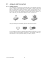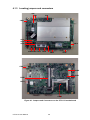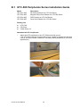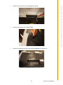
1
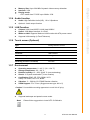
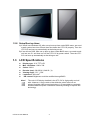
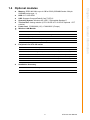
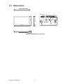
User Manual UTC-515 Intel® AtomTM D525 Processorbased Ubiquitous Touch Computer with 15.6” TFT LCD Copyright The documentation and the software included with this product are copyrighted 2011 by Advantech Co., Ltd. All rights are reserved. Advantech Co., Ltd. reserves the right to make improvements in the products described in this manual at any time without notice. No part of this manual may be reproduced, copied, translated or transmitted in any form or by any means without the prior written permission of Advantech Co., Ltd. Information provided in this manual is intended to be accurate and reliable. However, Advantech Co., Ltd. assumes no responsibility for its use, nor for any infringements of the rights of third parties, which may result from its use. Acknowledgements Award is a trademark of Award Software International, Inc. Intel and Celeron are trademarks of Intel Corporation. IBM, PC/AT, PS/2 and VGA are trademarks of International Business Machines Corporation. Intel and Pentium are trademarks of Intel Corporation. Microsoft Windows is a registered trademark of Microsoft Corp. RTL is a trademark of Realtek Semiconductor Co., Ltd. All other product names or trademarks are properties of their respective owners. For more information on this and other Advantech products, please visit our websites at: http://www.advantech.com http://www.advantech.com/ppc For technical support and service, please visit our support website at: http://support.advantech.com This manual is for the UTC-515. UTC-515 User Manual Part No. 2008C51500 Edition 1 Printed in Taiwan June 2011 ii Declaration of Conformity FCC Class A Note: This equipment has been tested and found to comply with the limits for a Class B digital device, pursuant to part 15 of the FCC Rules. These limits are designed to provide reasonable protection against harmful interference in a residential installation. This equipment generates, uses and can radiate radio frequency energy and, if not installed and used in accordance with the instructions, may cause harmful interference to radio communications. However, there is no guarantee that interference will not occur in a particular installation. If this equipment does cause harmful interference to radio or television reception, which can be determined by turning the equipment off and on, the user is encouraged to try to correct the interference by one or more of the following measures: Reorient or relocate the receiving antenna. Increase the separation between the equipment and receiver. Connect the equipment into an outlet on a circuit different from that to which the receiver is connected. Consult the dealer or an experienced radio/TV technician for help. Warning! Any changes or modifications made to the equipment which are not expressly approved by the relevant standards authority could void your authority to operate the equipment. Packing List Before you begin installing UTC-515, please make sure that the following materials have been shipped: UTC-515 series Accessories for UTC-515 – Warranty card – DC 12V/ 60W power Adapter – 1 x Utility CD – A packet of screws If any of these items are missing or damaged, contact your distributor or sales representative immediately. Ordering information Part No. UTC-515-RE UTC-515-RXPE0E 1702002605 1702002600 1700000596 Description 15.6" Atom D525 Based fanless UTC with Resi.T/S. 2GB RAM UTC-515-RE with 2GB Memory/160GHDD/XPE Power cord 2P FRANCE 10A/16A 220V 1.83M 90D Power Cord 3P UL/CSA(USA) 125V 10A 1.83M 180D Power Cord (China) CCC,10A 250V, 3P 1830mm iii UTC-515 User Manual Technical Support and Assistance 1. 2. Visit the Advantech web site at http://support.advantech.com where you can find the latest information about the product. Contact your distributor, sales representative, or Advantech's customer service center for technical support if you need additional assistance. Please have the following information ready before you call: – Product name and serial number – Description of your peripheral attachments – Description of your software (operating system, version, application software, etc.) – A complete description of the problem – The exact wording of any error messages Warning! Danger of explosion if battery is incorrectly replaced. Replace only with the same or equivalent type recommended by the manufacturer. Dispose of used batteries according to the manufacturer's instructions. Warning! 1. 2. 3. 4. 5. Input voltage rated 12 V, 5 A Use a 3 V @ 195 mA lithium battery Packing: please carry the unit with both hands, handle with care Maintenance: to properly maintain and clean the surfaces, use only approved products or clean with a dry applicator CompactFlash: Turn off power before inserting or removing CompactFlash storage card. Contact information: Our European representative: Advantech Europe GmbH Kolberger Strafle 7 D-40599 Dβsseldorf, Germany Tel: 49-211-97477350 Fax: 49-211-97477300 UTC-515 User Manual iv Safety Instructions 1. 2. 3. Read these safety instructions carefully. Keep this User Manual for later reference. Disconnect this equipment from any AC outlet before cleaning. Use a damp cloth. Do not use liquid or spray detergents for cleaning. 4. For plug-in equipment, the power outlet socket must be located near the equipment and must be easily accessible. 5. Keep this equipment away from humidity. 6. Put this equipment on a reliable surface during installation. Dropping it or letting it fall may cause damage. 7. The openings on the enclosure are for air convection. Protect the equipment from overheating. DO NOT COVER THE OPENINGS. 8. Make sure the voltage of the power source is correct before connecting the equipment to the power outlet. 9. Position the power cord so that people cannot step on it. Do not place anything over the power cord. 10. All cautions and warnings on the equipment should be noted. 11. If the equipment is not used for a long time, disconnect it from the power source to avoid damage by transient overvoltage. 12. Never pour any liquid into an opening. This may cause fire or electrical shock. 13. Never open the equipment. For safety reasons, the equipment should be opened only by qualified service personnel. 14. If one of the following situations arises, get the equipment checked by service personnel: 15. The power cord or plug is damaged. 16. Liquid has penetrated into the equipment. 17. The equipment has been exposed to moisture. 18. The equipment does not work well, or you cannot get it to work according to the user's manual. 19. The equipment has been dropped and damaged. 20. The equipment has obvious signs of breakage. 21. DO NOT LEAVE THIS EQUIPMENT IN AN ENVIRONMENT WHERE THE STORAGE TEMPERATURE MAY GO BELOW -20° C (-4° F) OR ABOVE 60° C (140° F). THIS COULD DAMAGE THE EQUIPMENT. THE EQUIPMENT SHOULD BE IN A CONTROLLED ENVIRONMENT. 22. CAUTION: DANGER OF EXPLOSION IF BATTERY IS INCORRECTLY REPLACED. REPLACE ONLY WITH THE SAME OR EQUIVALENT TYPE RECOMMENDED BY THE MANUFACTURER, DISCARD USED BATTERIES ACCORDING TO THE MANUFACTURER'S INSTRUCTIONS. 23. The sound pressure level at the operator's position according to IEC 704-1:1982 is no more than 70 dB (A). DISCLAIMER: This set of instructions is given according to IEC 704-1. Advantech disclaims all responsibility for the accuracy of any statements contained herein. v UTC-515 User Manual UTC-515 User Manual vi Contents Chapter 1 General Information ............................1 1.1 1.2 Introduction ............................................................................................... 2 General Specifications .............................................................................. 2 1.2.1 General ......................................................................................... 2 1.2.2 Standard PC functions .................................................................. 2 1.2.3 VGA Interface ............................................................................... 2 1.2.4 Audio function ............................................................................... 3 1.2.5 LAN Function ................................................................................ 3 1.2.6 Touch screen (Optional) ............................................................... 3 1.2.7 Environment.................................................................................. 3 1.2.8 Setup Boot up timer: ..................................................................... 4 LCD Specifications.................................................................................... 4 Optional modules ...................................................................................... 5 Dimensions ............................................................................................... 6 Figure 1.1 Dimensions of UTC-515 ............................................. 6 1.3 1.4 1.5 Chapter 2 System Setup .......................................7 2.1 2.5 A Quick Tour of the UTC-515.................................................................... 8 Figure 2.1 Front view of UTC-515 ............................................... 8 Figure 2.2 Rear view of UTC-515 ................................................ 8 Installation Procedures.............................................................................. 9 2.2.1 Connecting the power cord ........................................................... 9 2.2.2 Connecting the keyboard or mouse .............................................. 9 2.2.3 Switching on the power................................................................. 9 Figure 2.3 Connect the power cord to the DC inlet...................... 9 Running the BIOS Setup Program .......................................................... 10 Installing System Software...................................................................... 10 2.4.1 Method 1: Ethernet ..................................................................... 10 2.4.2 Method 2: External USB CD-ROM.............................................. 10 Installing the Drivers................................................................................ 11 3 Hardware Install and Upgrades ........13 3.1 3.2 3.4 Introduction ............................................................................................. 14 Installing the 2.5" Hard Disk Drive (HDD) ............................................... 14 Figure 3.1 Installing primary 2.5" HDD ...................................... 14 Installing the Compact Flash card........................................................... 15 Figure 3.2 Installing the Compact Flash card ............................ 15 Installing the WLAN................................................................................. 15 4 Jumper Settings and Connectors ....23 4.1 Jumpers and Connectors ........................................................................ 24 4.1.1 Setting jumpers ........................................................................... 24 4.1.2 Jumpers and connectors............................................................. 25 Table 4.1: Jumpers and Connector functions............................ 25 4.1.3 Locating jumpers and connectors ............................................... 26 Figure 4.1 Jumpers and Connectors on the UTC-515 motherboard 26 Jumpers .................................................................................................. 27 4.2.1 Jumper list................................................................................... 27 2.2 2.3 2.4 Chapter 3.3 Chapter 4.2 vii UTC-515 User Manual 4.2.2 Table 4.2: Jumper List............................................................... 27 Jumper Settings.......................................................................... 27 Table 4.3: J2: COM2 Setting ..................................................... 27 Table 4.4: J3: AT / ATX Power SEL .......................................... 27 Table 4.5: J4: Clear COMS ....................................................... 28 Table 4.6: J5: PAN VOL SEL .................................................... 28 Appendix A I/O Pin Assignments ......................... 29 A.1 PIN Assignments .................................................................................... 30 Table A.1: CN1: Audio ............................................................... 30 Table A.2: CN3: SATA............................................................... 30 Table A.3: CN5: SATA HDD Power........................................... 31 Table A.4: CN6: 12 V Power Input............................................. 31 Table A.5: CN11: SMBus........................................................... 32 Table A.6: CN13: Inverter Power Output ................................... 32 Table A.7: CN14: Internal USB.................................................. 33 Table A.8: CN15: Internal USB.................................................. 33 Table A.9: CN16: 18 or 24 bits LVDS Panel.............................. 34 Table A.10:CN18: LAN1 ............................................................. 35 Table A.11:CN19: LAN2 ............................................................. 35 Table A.12:CN20: Power Switch (Low Active)............................ 35 Table A.13:CN22: HDMI (Optional) ............................................ 36 Table A.14:CN23: Reset............................................................. 37 Table A.15:CN24: External USB................................................. 37 Table A.16:CN25: External USB................................................. 38 Table A.17:CN26: COM1............................................................ 38 Table A.18:CN27: VGA............................................................... 39 Table A.19:CN28: Mini PCIE lock .............................................. 40 Table A.20:CN29: Mini PCIE slot................................................ 40 Table A.21:CN30: DDR3 SODIMM............................................. 42 Table A.22:CN32: CF ................................................................. 43 Appendix B Peripherals Installation Guide ......... 45 B.1 UTC-500 Peripherals Series Installation Guide ...................................... 46 Appendix C WDT.................................................... 49 C.1 Watchdog Timer Sample Code............................................................... 50 UTC-515 User Manual viii Chapter 1 1 General Information This chapter gives background information on the UTC-515. Sections include: Introduction General Specifications LCD Specifications Dimensions 1.1 Introduction The UTC-515 is an Intel low-power Intel® AtomTM D525 processor computer that is designed to serve as a interactive self-service terminal and as a multimedia computer. It is a PC-based system with 15.6" TFT LCD display, on-board PCIe Ethernet controller, one COM port and VGA connector. With a built in internal Compact flash slot (for CF card), one SATA connector for HDD and an mini PCIe expansion socket, the UTC-515 is a compact and user-friendly multi-function computer. In addition, its “fit anywhere” design makes it very flexible and able to be used in many different kinds of installations. It can be wall mounted or stood upright on a desktop. For system integrators, this simple, complete, compact and highly integrated multimedia system lets you easily build UTC-515 into your applications. Common industrial applications include self-transaction & health care, information kiosk & interactive signage. UTC-515 is a reliable, cost-effective solution for your application requirements. 1.2 General Specifications 1.2.1 General Dimensions: 384.6 mm (L) x 236.5 mm (H) x 40 mm (D) Weight: 5 kg Power supply: ATX type Input Voltage: +12 VDC, 5 A Power adaptor: AC/DC (Standard Build in) 12 V, 60 W Input voltage:100 ~ 240 VAC Output voltage: 12 V @ 5 A Disk drive housing: Space for one 2.5" SATA HDD Front panel: IP54/NEMA4 compliant 1.2.2 Standard PC functions CPU: Intel® Atom™ D525 at 1.8 GHz with 1MB L2 cache BIOS: AMI 16 MB Flash BIOS via SPI System chipset: Intel® AtomTM D525 + Intel ICH8M 2nd level cache: 512 KB x 2 System memory: Supports DDR3 800 MHz up to 4 GB for D525 ( SODIMM Socket: 204-pin SODIMM socket type *1) Serial ports: 1* external COM Universal serial bus (USB) port: Supports up to 2 USB V2.0 Mini PCI-E bus expansion slot: Accepts one mini PCI-E device (wireless LAN card) Solid State Disk: Supports CompactFlash card type I/II (True IDE mode) Watchdog timer: Single chip Watchdog 255-level interval timer, setup by software Power management: Full ACPI (Advanced Configuration and Power Interface) 2.0 Supports S0, S1, S3,S4, S5 1.2.3 VGA Interface Embedded Gen3.5+ GFX Core – DVMT 3.0 (Dynamic Video Memory Technology) – DirectX* 9 compliant Pixel Shader 2.0 – Intel® Clear Video Technology Chipset: The GPU Contains a refresh of the third generation graphics core UTC-515 User Manual 2 Memory Size: Up to 224 MB of dynamic video memory allocation Interface: VGA Display mode: – CRT: Intel® Atom™ D525 up to 2048 x 1536 1.2.4 Audio function Audio: High Definition Audio (HD), 1 W x 2 Speakers Optional - Audio output function Chipset: LAN1 Intel 82567V, LAN2 Intel 82583V Speed: 1000 Mbps /Interface: 2 x RJ45 Wake-on-LAN: Supports Wake-on-LAN function with ATX power control Supports LAN teaming (in Fault Tolerance) 1.2.6 Touch screen (Optional) Type Analog Resistive 5 wires Resolution 1024 x 1024 Light Transmission 80% Controller USB interface Power Consumption <5 V @ 60 mA Software Driver Supports Windows XP/ 7/ XPE Durability (touches in a lifetime) 36 million 1.2.7 Environment Operating temperature: 0 ~ 40° C (32 ~ 104° F) Storage temperature: -20 ~ 60° C Relative humidity: 10 ~ 95% @ 40° C (non-condensing) Shock: 10 G peak acceleration (11 ms duration) Certification: EMC: CE, FCC, BSMI, VCCI. Safety: UL 60950, CB, CCC, BSMI Vibration: 5 ~ 500 Hz 0.5 G RMS Random vibration VESA Support: 75 x 75 mm (Suggest screws type- M4 x 5) Caution! Use suitable mounting apparatus to avoid risk of injury. Supports landscape and portrait screen mode Note! Please follow suggestion to install UTC-515 Models. 3 UTC-515 User Manual General Information 1.2.5 LAN Function Chapter 1 1.2.8 Setup Boot up timer: A) If we will use Windows OS, after set up boot up timer under BIOS menu, we need to wait system boot into OS and then shut down the UTC-515 properly. Then the UTC-515 can boot up automatically at the timing we set. B) If we will use DOS, after set up boot up timer under BIOS menu, we need to wait until we see C:/ and then turn off the UTC-515 by power switch. Then the UTC515 can boot up automatically at the timing we set. 1.3 LCD Specifications Display type: 15.6" TFT LCD Max. resolution: 1366 x 768 Colors: 262 K Dot size (mm): 248.25(H) X 248.25 ( V) Viewing angle: 170 ° / 160° Luminance: 300 cd/m2 *VR control: Brightness could be modified through BIOS Note! UTC-515 User Manual The color LCD display installed in the UTC-515 is high-quality and reliable. However, it may contain a few defective pixels which do not always illuminate. With current technology, it is impossible to completely eliminate defective pixels. Advantech is actively working to improve this technology. 4 Part No. Description 968EMW0038 Wireless IEEE 802.11 b/g/n AW-NE785 PCIE 1750006010 (Cable) 9680001060 2.0dBi Dipole short antenna 1750003222 5.0dBi Dipole long antenna Peripherals for UTC-500 series Part No. Description UTC-P01-A0E 2M Camera Module For UTC-5XX (USB connection) UTC-P02-A0E Magnet Strip Reader For UTC-5XX (USB connection) UTC-P03-A0E RFID Reader For UTC-5XX (USB connection) UTC-P06-A0E Smart Card Reader For UTC-5XX (USB connection) UTC-P07-A0E 2D Barcode Reader For UTC-5XX (USB Connection) UTC-P21-A0E 4 in 1 Modules Barcode reader + RFID + Card reader + MSR Installation Accessory Part No. Description UTC-520-STAND1E Desktop Stand for UTC-520 5 UTC-515 User Manual General Information Memory: DDR3 800 MHz up to 4 GB for D525 (SODIMM Socket: 204-pin SODIMM socket type *1) HDD: 2.5" SATA HDD SSD: Supports CompactFlash® Card TYPE I/II Operating System: Windows XP/ XPE/ 7/ Embedded Standard 7 Touchscreen: Analog resistive (UTC-515-RE/ UTC-515-R1E Optional - PCT solution) Power cord: 1702002600 ( US) 1702002605 (Europe) Wireless LAN Module: Chapter 1 1.4 Optional modules 1.5 Dimensions 218.25 40 48 40 Figure 1.1 Dimensions of UTC-515 UTC-515 User Manual 154.80 ANTENNA HOLE 236.50 384.60 75 75 VESA Hole M4 depth=5mm 6 Chapter 2 2 System Setup This chapter details system setup on the UTC-515. Sections include: A Quick Tour of the UTC-515 Installation procedures Running the BIOS Setup Program Installing System Software 2.1 A Quick Tour of the UTC-515 Before you start to set up the UTC-515, take a moment to become familiar with the locations and purposes of the controls, drives, connectors and ports, which are illustrated in the figures below. When you place the UTC-515 upright on the desktop, its front panel appears as shown in Figure 2.1. Figure 2.1 Front view of UTC-515 When you turn the UTC-515 around and look at its rear cover, you will find the I/O section as shown in Fig. 2.2. (The I/O section includes various I/O ports, including serial ports, Ethernet ports, USB ports, VGA, and Compact Flash slot.) Figure 2.2 Rear view of UTC-515 UTC-515 User Manual 8 B C D E F Chapter 2 A G H E. VGA F. DC Inlet G. Power Switch H. Compact Flash slot 2.2 Installation Procedures 2.2.1 Connecting the power cord The UTC-515 can be powered by a DC electrical outlet. Be sure to always handle the power cords by holding the plug ends only. Please follow the Figure 2.5 to connect the male plug of the power cord to the DC inlet of the UTC-515. 2.2.2 Connecting the keyboard or mouse Before you start the computer, please connect keyboard port on the I/O section of the UTC-515. 2.2.3 Switching on the power When you look at the rear side of the UTC-515, you will see the power switch as shown in Figure 2.2. DC inlet Power cord AC/DC Power adapter Figure 2.3 Connect the power cord to the DC inlet 9 UTC-515 User Manual System Setup A. Antenna/ Audio Line-out (option) B. USB 2.0 x 2 C. Gigabit LAN x 2 D. COM port 2.3 Running the BIOS Setup Program Your UTC-515 is likely to have been properly set up and configured by your dealer prior to delivery. You may still find it necessary to use the UTC-515's BIOS (Basic Input-Output System) setup program to change system configuration information, such as the current date and time or your type of hard drive. The setup program is stored in read-only memory (ROM). It can be accessed either when you turn on or reset the UTC-515, by pressing the “Del” key on your keyboard immediately after powering on the computer. The settings you specify with the setup program are recorded in a special area of memory called CMOS RAM. This memory is backed up by a battery so that it will not be erased when you turn off or reset the system. Whenever you turn on the power, the system reads the settings stored in CMOS RAM and compares them to the equipment check conducted during the power on self-test (POST). If an error occurs, an error message will be displayed on screen, and you will be prompted to run the setup program. 2.4 Installing System Software Recent releases of operating systems from major vendors include setup programs which load automatically and guide you through hard disk preparation and operating system installation. The guidelines below will help you determine the steps necessary to install your operating system on the UTC-515 hard drive. Note! Some distributors and system integrators may have already preinstalled system software prior to shipment of your UTC-515. Installing software requires an installed HDD. Software can be loaded in the UTC-515 using any of four methods: 2.4.1 Method 1: Ethernet You can use the Ethernet port to download software to the HDD. 2.4.2 Method 2: External USB CD-ROM If required, insert your operating system's installation or setup diskette into the diskette drive until the release button pops out. The BIOS of UTC-515 supports system boot-up directly from the CD-ROM drive. You may also insert your system installation CD-ROM into the CD-ROM drive. Power on your UTC-515 or reset the system by pressing the “Ctrl+Alt+Del” keys simultaneously. The UTC-515 will automatically load the operating system from the diskette or CD-ROM. If you are presented with the opening screen of a setup or installation program, follow the instructions on screen. The setup program will guide you through preparation of your hard drive, and installation of the operating system. If you are presented with an operating system command prompt, such as A:\>, then you must partition and format your hard drive, and manually copy the operating system files to it. Refer to your operating system user manual for instructions on partitioning and formatting a hard drive. UTC-515 User Manual 10 After installing your system software, you will be able to set up the Ethernet, XGA, audio, and touchscreen functions. All drivers are stored in a CD-ROM disc entitled “Drivers and Utilities” which can be found in your accessory box. The various drivers and utilities in the CD-ROM disc have their own text files which helps users install the drivers and understand their functions. These files are a very useful supplement to the information in this manual. The drivers and utilities used for the UTC-515 are subject to change without notice. If in doubt, check Advantech's website or contact our application engineers for the latest information regarding drivers and utilities. 11 UTC-515 User Manual System Setup Note! Chapter 2 2.5 Installing the Drivers UTC-515 User Manual 12 Chapter 3 3 Hardware Install and Upgrades This chapter details installing the UTC-515 hardware. Sections include: Overview of Hardware Installation and Upgrading Installing the 2.5" Hard Disk Drive (HDD) Installing the Compact Flash Installing the WLAN 3.1 Introduction The UTC-515 consists of a PC-based computer that is housed in an Aluminum extrusion. You can install a HDD, DRAM, and Compact Flash by removing the rear cover. Any maintenance or hardware upgrades can be easily completed after removing the rear cover. Warning! Do not remove the rear cover until you have verified that no power is flowing within the UTC-515. Power must be switched off and the power cord must be unplugged. Every time you service the UTC-515, you should be aware of this. 3.2 Installing the 2.5" Hard Disk Drive (HDD) You can attach one Serial Advanced Technology Attachment (SATA) hard disk drive to the UTC-515's internal controller. The SATA controller supports faster data transfer and allows the SATA hard drive to exceed 150 MB. The following are instructions for installation: 1. Detach and remove the rear cover. 2. Place the HDD in the metal bracket, and tighten the screws (see Figure 3.1). 3. The HDD cable (SATA 7P+1*5P-2.5/SATA(15+7)P) is next to the metal brace. Connect the HDD cable to the motherboard (CN3/CN5). Plug the other end of the cable into the SATA hard drive. 4. Put the rear cover on and tighten the screws. Figure 3.1 Installing primary 2.5" HDD UTC-520 User Manual 14 1. Please follow the Compact Flash card assembly as in the following diagram. (Please notice the direction of the CF Card) 3.4 Installing the WLAN Reserve two locations for the external Antenna. One is at the IO port, the other is at the rear cover. Customers can choose based on different applications. 1. Remove 17 pcs screws of back cover. 15 UTC-520 User Manual Hardware Install and Upgrades Figure 3.2 Installing the Compact Flash card Chapter 3 3.3 Installing the Compact Flash card 2. Remove the "hole cover" on back cover with a slot screwdriver. 3. Remove connectors on the M/B. UTC-520 User Manual 16 Remove 4 screws on M/B. 5. Take the M/B then remove the DC-in cable. 6. Coaxial cable (Advantech P/N: 1750006010) Chapter 3 4. Hardware Install and Upgrades 17 UTC-520 User Manual 7. Put the black rubber gasket in SMA side first. 8. Connect the coaxial cable to "ANT1" on the WLAN card. 9. Install the WLAN card on M/B bottom side. UTC-520 User Manual 18 Chapter 3 10. Find the smooth side of the circle. Hardware Install and Upgrades 11. Install the cable into antenna bracket. 12. Install the washer & nut then screw in tight. Washer Nut 19 UTC-520 User Manual 13. Put the M/B back and the 4 screws on the M/B. 14. Put the antenna bracket on the stand and insert the 2 screws 15. Caution! -Do not let the antenna wire go between the stand & bracket. UTC-520 User Manual 20 Chapter 3 Hardware Install and Upgrades 16. Assemble all the connectors back. 17. Replace the 17 screws on the back cover. 21 UTC-520 User Manual 18. Assemble the Antenna. UTC-515 with the 5.0dBi dipole long antenna (Advantech P/N: 1750003222) UTC-515 with the 2.0dBi dipole short antenna (Advantech P/N: 9680001060) UTC-520 User Manual 22 Chapter 4 4 Jumper Settings and Connectors This chapter tells how to set up the UTC-515 hardware, including instructions on setting jumpers and connecting peripherals, switches and indicators. Be sure to read all the safety precautions before you begin the installation procedures. Sections include: Jumpers and Connectors CMOS Clear for External RTC (J5) COM Port Interface VGA Interface Watchdog Timer Configuration 4.1 Jumpers and Connectors 4.1.1 Setting jumpers You can configure your UTC-515 to match the needs of your application by setting jumpers. A jumper is the simplest kind of electrical switch. It consists of two metal pins and a small metal clip (often protected by a plastic cover) that slides over the pins to connect them. To 'close’ a jumper, you connect the pins with the clip. To ‘open’ a jumper you remove the clip. Sometimes a jumper will have three pins, labeled 1, 2, and 3. In this case, you would connect either pins 1 and 2 or pins 2 and 3. open closed closed 2-3 The jumper settings are schematically depicted in this manual as follows:. open closed closed 2-3 A pair of needle-nose pliers may be helpful when working with jumpers. If you have any doubts about the best hardware configuration for your application, contact your local distributor or sales representative before you make any changes. UTC-515 User Manual 24 The motherboard of the UTC-515 has a number of jumpers and connectors that allow you to configure your system to suit your applications. The table below lists the function of each of the board’s jumpers. Table 4.1: Jumpers and Connector functions Label Function CN1 Audio CN3 SATA SATA Power CN6 12V Power Input CN11 SMBus CN13 Inverter Power Output CN14 Internal USB CN15 Internal USB CN16 24-bit LVDS Panel CN18/CN19 LAN1 & LAN2 CN20 Power Switch CN23 Reset CN24 External USB CN25 External USB CN26 COM1 CN27 VGA CN28 Mini PCIe lock CN29 Mini PCIe slot CN30 DDR3 SODIMM CN31 BIOS Socket CN32 CF 25 Jumper Settings and Connectors CN5 Chapter 4 4.1.2 Jumpers and connectors UTC-515 User Manual 4.1.3 Locating jumpers and connectors CN5 CN1 CN3 CN20 CN11 CN14 CN15 CN16 CN25CN24 CN18 CN19 CN26 CN23 CN6 CN28 CN31 CN30 CN13 CN32 Figure 4.1 Jumpers and Connectors on the UTC-515 motherboard UTC-515 User Manual 26 Chapter 4 4.2 Jumpers 4.2.1 Jumper list Table 4.2: Jumper List COM2 Setting J3 AT / ATX Power SEL J4 Clear CMOS J5 Panel Voltage SEL 4.2.2 Jumper Settings Table 4.3: J2: COM2 Setting Part Number 1653003260 Footprint HD_3x2P_79 Description PIN HEADER 3*2P 180D(M) 2.0mm SMD SOUARE PIN Setting Function (1-2)* RS232 (3-4) RS485 (5-6) RS422 Table 4.4: J3: AT / ATX Power SEL Part Number 1653002101 Footprint HD_2x1P_79_D Description PIN HEADER 2*1P 180D(M)SQUARE 2.0mm DIP W/O Pb Setting Function (1-2) AT Power SEL EMPTY ATX Power 27 UTC-515 User Manual Jumper Settings and Connectors J2 Table 4.5: J4: Clear COMS Part Number 1653003101 Footprint HD_3x1P_79_D Description PIN HEADER 3*1P 180D(M) 2.0mm DIP SQUARE W/O Pb Setting Function (1-2)* Normal (2-3) Clear CMOS Table 4.6: J5: PAN VOL SEL Part Number 1653003101 Footprint HD_3x1P_79_D Description PIN HEADER 3*1P 180D(M) 2.0mm DIP SQUARE W/O Pb Setting Function (1-2)* +5V (2-3) +3V UTC-515 User Manual 28 Appendix A A I/O Pin Assignments A.1 PIN Assignments Table A.1: CN1: Audio Part Number 1653205260 Footprint HD_5x2P_79_BOX Description BOX HEADER SMD 5*2 180D (M) 2.0mm Pin Pin Name 1 LOUTR 2 LINR 3 GND 4 GND 5 LOUTL 6 LINL 7 GND 8 GND 9 MIC1R 10 MIC1L Matching Cable: 1703100152 Table A.2: CN3: SATA Part Number 1654002320 Footprint FOX_LD1107V-S33T5 Description Serial ATA 7P 1.27 90D(M) SMD LD1107V-S33T5 Pin Pin Name 1 GND 2 TX+ 3 TX- 4 GND 5 RX- 6 RX+ 7 GND UTC-515 User Manual 30 Appendix A I/O Pin Assignments Table A.3: CN5: SATA HDD Power Part Number 1655306020 Footprint WHL6V-2M Description WAFER BOX 2.0mm 6P 180D(M) W/LOCK Pin Pin Name 1 +5V 2 GND 3 NC 4 GND 5 NC 6 NC Table A.4: CN6: 12 V Power Input Part Number 1655404090 Footprint ATXCON-2X2-42 Description ATX PWR CONN. 2*2P 180D 4.2mm 24W4310-04S10-01T Pin Pin Name 1 +12 V 2 +12 V 3 GND 4 GND 31 UTC-515 User Manual Table A.5: CN11: SMBus Part Number 1655904020 Footprint FPC4V-125M Description Wafer SMT 1.25mmS/T type 4P 180D(M) 85205-04001 Pin Pin Name 1 GND 2 SMB_DAT 3 SMB_CLK 4 +5V Table A.6: CN13: Inverter Power Output Part Number 1655000453 Footprint WHL5V-2M-24W1140 Description WAFER BOX 2.0mm 5P 180D(M) DIP WO/pb JIH VEI Pin Pin Name 1 +12V 2 GND 3 ENABKL 4 VBR 5 +5V UTC-515 User Manual 32 Part Number 1653005260 Footprint HD_5x2P_79_N10 Description PIN HEADER 2*5P 180D(M) 2.0mm SMD IDIOT-PROOF Pin Pin Name 1 +5V 2 +5V 3 A_D- 4 B_D- 5 A_D+ 6 B_D+ 7 GND 8 GND 9 GND Matching Cable: 1703100121 Table A.8: CN15: Internal USB Part Number 1653005260 Footprint HD_5x2P_79_N10 Description PIN HEADER 2*5P 180D(M) 2.0mm SMD IDIOT-PROOF Pin Pin Name 1 +5V 2 +5V 3 A_D- 4 B_D- 5 A_D+ 6 B_D+ 7 GND 8 GND 9 GND Matching Cable: 1703100121 33 UTC-515 User Manual Appendix A I/O Pin Assignments Table A.7: CN14: Internal USB Table A.9: CN16: 18 or 24 bits LVDS Panel Part Number 1653910261 Footprint SPH10X2 Description *CONN. SMD 10*2P 180D(M)DF13-20DP-1.25V(91) HRS Pin Pin Name 1 GND 2 GND 3 LVDS0_D0+ 4 NC 5 LVDS0_D0- 6 NC 7 LVDS0_D1+ 8 NC 9 LVDS0_D1- 10 NC 11 LVDS0_D2+ 12 NC 13 LVDS0_D2- 14 NC 15 LVDS0_CLK+ 16 LVDS0_z_D3+ 17 LVDS0_CLK- 18 LVDS0_z_D3- 19 +5V or +3.3V 20 +5V or +3.3V UTC-515 User Manual 34 Part Number 1652002996 Footprint RJ45_14P_RTA-195AAK1A Description Phone Jack RJ45 14P 90D(M) DIP RTA-195AAK1A Pin Pin Name Table A.11: CN19: LAN2 Part Number 1652002996 Footprint RJ45_14P_RTA-195AAK1A Description Phone Jack RJ45 14P 90D(M) DIP RTA-195AAK1A Pin Pin Name Table A.12: CN20: Power Switch (Low Active) Part Number 1655302020 Footprint WF_2P_79_BOX_R1_D Description WAFER BOX 2P 180D(M) 2.0mm W/Lock Pin Pin Name 1 PSIN 2 GND 35 UTC-515 User Manual Appendix A I/O Pin Assignments Table A.10: CN18: LAN1 Table A.13: CN22: HDMI (Optional) CN22 HDMI Part Number 1654009225 Footprint HDMI_19P_QJ51193-FFD4-4F Description HDMI Conn 19P 0.5mm 90D(M) SMD QJ51193-FFB4-7F Pin Pin Name 1 HDMI_D2+ 2 GND 3 HDMI_D2- 4 HDMI_D1+ 5 GND 6 HDMI_D1- 7 HDMI_D0+ 8 GND 9 HDMI_D0- 10 HDMI_CLK+ 11 GND 12 HDMI_CLK- 13 HDMI_z_CEC 14 NC 15 HDMI_SCL 16 HDMI_SDA 17 GND 18 +V5_HDMI 19 HDMI_z_DET UTC-515 User Manual 36 Appendix A I/O Pin Assignments Table A.14: CN23: Reset Part Number 1655302020 Footprint WF_2P_79_BOX_R1_D Description WAFER BOX 2P 180D(M) 2.0mm W/Lock Pin Pin Name 1 RESET# 2 GND Table A.15: CN24: External USB Part Number 1654904105 Footprint USB-V-4A Description USB CON. 4P 90D(F) DIP A TYPE RoHS Pin Pin Name 1 +5V 2 D- 3 D+ 4 GND 37 UTC-515 User Manual Table A.16: CN25: External USB Part Number 1654904105 Footprint USB-V-4A Description USB CON. 4P 90D(F) DIP A TYPE RoHS Pin Pin Name 1 +5V 2 D- 3 D+ 4 GND Table A.17: CN26: COM1 Part Number 1654000056 Footprint DBCOM-VM5MS Description D-SUB CON. 9P 90D(M)DIP 070241MR009S200ZU SUYIN Pin Pin Name 1 DCD# 2 RXD 3 TXD 4 DTR# 5 GND 6 DSR# 7 RTS# 8 CTS# 9 RI# UTC-515 User Manual 38 Part Number 1654000055 Footprint DBVGA-VF5MS Description D-SUB Conn. 15P 90D(F) DIP 070242FR015S200ZU Pin Pin Name 1 RED 2 GREEN 3 BLUE 4 NC 5 GND 6 GND 7 GND 8 GND 9 NC 10 GND 11 NC 12 DDAT 13 HSYNC 14 VSYNC 15 DCLK 39 UTC-515 User Manual Appendix A I/O Pin Assignments Table A.18: CN27: VGA Table A.19: CN28: Mini PCIE lock Part Number 1654002539 Footprint FOX_AS0B226-S68K7F_HOLDER Description MINI PCI Express LATCH 52P 90D SMD 6.8mm Pin Pin Name Table A.20: CN29: Mini PCIE slot Part Number 1654002538 Footprint FOX_AS0B226-S68K7F Description MINI PCI express 52P 90D SMD H=6.8mm Pin Pin Name 1 WAKE# 2 +3.3V or +3.3VSB 3 NC 4 GND 5 NC 6 +1.5V 7 CLKREQ# 8 NC 9 GND 10 NC 11 REFCLK- 12 NC 13 REFCLK+ 14 NC 15 GND UTC-515 User Manual 40 Appendix A I/O Pin Assignments Table A.20: CN29: Mini PCIE slot 16 NC 17 NC 18 GND 19 NC 20 NC 21 GND 22 PERST# 23 PERn0 24 +3.3VSB 25 PERp0 26 GND 27 GND 28 +1.5V 29 GND 30 SMB CLK 31 PETn0 32 SMB DAT 33 PETp0 34 GND 35 GND 36 USB D- 37 GND 38 USB D+ 39 +3.3V or +3.3VSB 40 GND 41 +3.3V or +3.3VSB 42 NC 43 GND 44 NC 45 NC 46 NC 47 NC 48 +1.5V 49 NC 50 GND 51 NC 52 +3.3V or +3.3VSB 53 NC 54 NC 55 GND 56 GND 41 UTC-515 User Manual Table A.21: CN30: DDR3 SODIMM Part Number 1651001904 Footprint DDR-SODIMM-STD65 Description SKT DIMM 200P DDR2 H=6.5mm STD SMD WO/Pb Pin Pin Name 1 VREF 2 GND 3 GND 4 DQ59 5 DQ63 6 DQ58 7 DQ62 8 GND 9 GND 10 DM7 11 DQS#7 12 GND 13 DQS7 14 DQ57 15 GND 16 DQ56 17 DQ61 18 GND 19 DQ60 20 DQ51 21 GND 22 DQ50 23 DQ55 UTC-515 User Manual 42 Appendix A I/O Pin Assignments Table A.21: CN30: DDR3 SODIMM 24 GND 25 DQ54 26 DM6 Table A.22: CN32: CF Part Number 1653002919 Footprint CF_50P_CFCMD-35T15W100 Description CF Type2 Conn.50P 90D(M) SMD WO/Pb CFCMD-35T15W1 Pin Pin Name 1 GND 2 D03 3 D04 4 D05 5 D06 6 D07 7 CS0# 8 GND 9 GND 10 GND 11 GND 12 GND 13 +5V 14 GND 15 GND 16 GND 17 GND 18 A02 19 A01 20 A00 21 D00 22 D01 23 D02 43 UTC-515 User Manual Table A.22: CN32: CF 24 NC 25 CD2# 26 CD1# UTC-515 User Manual 44 Appendix B B Peripherals Installation Guide B.1 UTC-500 Peripherals Series Installation Guide Model UTC-P01-A0E UTC-P02-A0E UTC-P03-A0E UTC-P06-A0E Description 2M Camera Module for UTC-500 Series Magnetic Stripe Card Reader for UTC-500 Series RFID Reader for UTC-500 Series Smart Card Reader for UTC-500 Series Packing List UTC-PXX CD-Driver Cable Clamp x 2 Assemble the UTC-Peripherals 1. Attach the UTC-peripheral to the UTC 500 series side groove. (The UTC-500's uniquely designed side groove creates an attachment area that runs all around the frame; customer's can easily attach peripherals to it for their applications.) UTC-515 User Manual 46 Fasten the 2 screws to fix the peripheral in place. 3. Connect the cable to an I/O port (USB). 4. Choose a location to put the cable clamp and attach the cable to it. Appendix B Peripherals Installation Guide 2. Attaching a peripheral on the top of the unit 47 UTC-515 User Manual Attaching a peripheral on the bottom of the unit An attachment to the left side UTC-515 User Manual 48 Appendix C WDT C C.1 Watchdog Timer Sample Code Watchdog function: ;The SCH3114 Runtime base I/O address is A00h ;Setting WatchDog time value location at offset 66h ;If set value "0", it is mean disable WatchDog function. Superio_GPIO_Port = A00h mov dx,Superio_GPIO_Port + 66h mov al,00h out dx,al .model small .486p .stack 256 .data SCH3114_IO EQU A00h .code org 100h .STARTup ;==================================================== ;47H ;enable WDT function bit [0]=0Ch ;==================================================== mov dx,SCH3114_IO + 47h mov al,0Ch out dx,al ;==================================================== ;65H ;bit [1:0]=Reserved ;bit [6:2]Reserve=00000 ;bit [7] WDT time-out Value Units Select ;Minutes=0 (default) Seconds=1 ;==================================================== mov dx,SCH3114_IO + 65h ; mov al,080h out dx,al ;==================================================== ;66H ;WDT timer time-out value ;bit[7:0]=0~255 ;==================================================== mov dx,SCH3114_IO + 66h mov al,01h out dx,al ;==================================================== ;bit[0] status bit R/W ;WD timeout occurred =1 UTC-515 User Manual 50 51 UTC-515 User Manual Appendix C WDT ;WD timer counting = 0 ;==================================================== mov dx,SCH3114_IO + 68h mov al,01h out dx,al .exit END www.advantech.com Please verify specifications before quoting. This guide is intended for reference purposes only. All product specifications are subject to change without notice. No part of this publication may be reproduced in any form or by any means, electronic, photocopying, recording or otherwise, without prior written permission of the publisher. All brand and product names are trademarks or registered trademarks of their respective companies. © Advantech Co., Ltd. 2011 53 XXX-XXXX User Manual