1
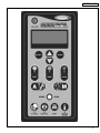
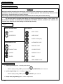
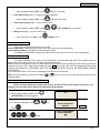
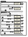
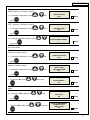
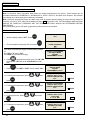
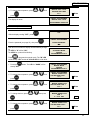
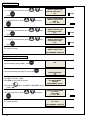
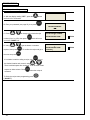
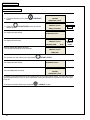
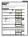
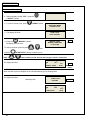
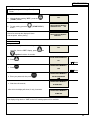
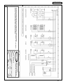
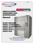
REV. E Cooler is Better!TM INSTALLATION, OPERATION AND MAINTENANCE Manual BLAST CHILLERS MODEL AP40BC250-12 MODEL AP40BC250-2-12 MODEL BCCP-1 MODEL BCCP-2 MODEL BCIP American Panel Corporation 5800 S.E. 78th Street, Ocala, Florida 34472-3412 Phone: (352) 245-7055 Fax: (352) 245-0726 E-mail: [email protected] Thank you, and congratulations on your purchase of an American Panel blast chiller. We take great pride in engineering and manufacturing each of our products. With the goal of providing the highest accuracy and quality possible, our state-of-the-art manufacturing and quality control facility enables us to continually explore new technologies so that we can provide you with the finest equipment in the industry. Because of our commitment to your satisfaction, we have developed this Installation, Operation, and Maintenance manual to guide you through the complete installation process, and to help you maintain your equipment properly. Familiarization and compliance with this manual will ensure you years of trouble-free operation. On occasion situations can arise and will require the help of the factory, whether it be technical information, service or replacement of parts. We have a highly trained Customer Service and Parts Department available to help when these situations arise. We also offer a national network of service agencies that may be contacted for warranty and out-of-warranty service. When contacting the factory, please refer to the equipment serial number which can be located on the identification plate positioned on the side of the control panel. Thank you once again for your purchase of American Panel equipment. “Our reputation rests on the steadfast pursuit of your satisfaction”. American Panel Corporation 5800 S.E. 78 th Street, Ocala, Florida 34472-3412 Phone: (352) 245-7055 Fax: (352) 245-0726 E-mail: [email protected] INDEX Index Index ....................................................................................................................................................................................... 1 A. Introduction ......................................................................................................................................................................... 3 A.1. Controller Features....................................................................................................................................................... 3 A.1.1. Operating Modes.................................................................................................................................................... 3 A.1.1.1. Automatic Mode ............................................................................................................................................... 3 A.1.1.2. Manual Mode ................................................................................................................................................... 3 A.1.2. Operating Cycles.................................................................................................................................................... 4 A.1.2.1. Soft Chill Cycle................................................................................................................................................. 4 A.1.2.2. Hard Chill Cycle ............................................................................................................................................... 4 A.1.2.3. Holding Mode................................................................................................................................................... 4 A.1.2.4. Printer (Optional).............................................................................................................................................. 4 A.1.2.5. PC Connection (Optional) ................................................................................................................................ 4 B. Installation........................................................................................................................................................................... 6 B.1. Package Content .......................................................................................................................................................... 6 B.2. Initial Cabinet Preparation ............................................................................................................................................ 8 B.3. Single Unit Installation AP40BC250-12 And BCCP-1 .................................................................................................. 9 B.3.1. Electrical Connections.......................................................................................................................................... 14 B.4. Install The Thermostat Bulb ....................................................................................................................................... 17 B.5. BCIP Installation ......................................................................................................................................................... 18 B.6. Double Unit Installation AP40BC250-2-12, BCCP-2.................................................................................................. 19 C. Refrigeration Unit Installation ........................................................................................................................................... 20 C.1. Preparation................................................................................................................................................................. 20 C.2. Find The Location....................................................................................................................................................... 20 C.3. Refrigeration Lines Installation................................................................................................................................... 21 C.3.1. Installation At The Same Level ............................................................................................................................ 22 C.3.2. Installation At Different Levels ............................................................................................................................. 22 C.4. Connect The Remote Unit.......................................................................................................................................... 23 D. Programming The Controller ............................................................................................................................................ 24 D.1. Keyboard Keys ........................................................................................................................................................... 24 D.2. Key Combinations ...................................................................................................................................................... 24 D.3. Programming Modes .................................................................................................................................................. 25 D.4. Initial Programming .................................................................................................................................................... 25 D.4.1. Initial Programming Procedure And Parameters ................................................................................................. 25 D.5. Parameter Programming ............................................................................................................................................ 29 D.5.1. Parameter Programming For Automatic Mode .................................................................................................... 29 D.5.1.1. Soft Cycle – Automatic Mode ........................................................................................................................ 29 D.5.1.2. Hard Cycle – Automatic Mode ....................................................................................................................... 30 D.5.2. Parameter Programming Manual Mode............................................................................................................... 32 D.5.2.1. Soft Cycle – Manual Mode............................................................................................................................. 32 D.5.2.2. Hard Cycle – Manual Mode ........................................................................................................................... 33 D.5.3. UV Light Cycle Programming............................................................................................................................... 34 D.5.4. Defrost Cycle Programming................................................................................................................................. 35 D.6. Recipe Name Programming ....................................................................................................................................... 36 E. Operation .......................................................................................................................................................................... 37 E.1. Automatic Mode – Soft Chill ....................................................................................................................................... 37 E.2. Automatic Mode – Hard Chill...................................................................................................................................... 39 E.3. Manual Mode – Soft Chill ........................................................................................................................................... 41 E.4. Manual Mode – Hard Chill .......................................................................................................................................... 43 E.5. UV (STERILIZATION) CYCLE ................................................................................................................................... 45 E.6. DEFROST CYCLE ..................................................................................................................................................... 46 E.7. Thaw Cycle (Optional) ................................................................................................................................................ 47 E.7.1. Food Loading ....................................................................................................................................................... 47 E.7.2. Automatic Thaw Cycle ......................................................................................................................................... 47 E.7.3. Manual Thaw Cycle.............................................................................................................................................. 48 E.8. Preparing And Using The Optional Printer ................................................................................................................. 49 E.9. Clear Data .................................................................................................................................................................. 49 F. Printer................................................................................................................................................................................ 50 F.1. Loading The Paper ..................................................................................................................................................... 50 F.2. Removing The Paper.................................................................................................................................................. 50 F.3. Operating The Printer ................................................................................................................................................. 50 1 INTRODUCTION F.4. Printer Maintenance.................................................................................................................................................... 50 F.5. Replacing The Ribbon (No Paper In The Printer)....................................................................................................... 50 F.6. Replacing The Ribbon (With Paper In The Printer) .................................................................................................... 50 G. Maintenance And Cleaning .............................................................................................................................................. 51 H. Standard Warranty............................................................................................................................................................ 52 I. Appendix 1 Electrical Schematic 1..................................................................................................................................... 53 I.1. Appendix 2 Electrical Schematic 2............................................................................................................................... 54 J. Appendix 3 Parts List......................................................................................................................................................... 55 J.1. Appendix 4 Ordering Printer Supplies (Ribbon & Paper)............................................................................................ 56 2 INTRODUCTION A. Introduction The Models AP40BC250-12, AP40BC250-2-12, BCCP-1, BCCP-2, and BCIP Blast Chillers are used to rapidly chill cooked foods to temperatures suitable for storage in a refrigerator. Blast chillers are sophisticated refrigeration machines capable of lowering the core temperature of most foods from 160°F to 38°F in less than two hours. Blast chilling operations employ high velocity cooled air flow to assure even cooling of the entire food product, and to quickly bring the food temperature through the danger zone in which bacteria multiply rapidly. This is done in accordance with HACCP, FDA and all state regulations. Cooked food rapidly loses its quality and aroma if it is not served promptly. Natural bacteria growth, the main reason why food becomes stale, takes place at an exponential rate between 140°F and 40°F. However lower temperature has a hibernating effect that increases as the temperature drops, thereby gradually reducing bacterial activity until it stops altogether. Only fast reduction of the temperature at the product's core allows its initial characteristics to be maintained intact. The HurriChill™ blast chiller gets food through this high-risk temperature band rapidly, cooling the core of the product to 40°F within 90 minutes. This conserves food quality, color and aroma while increasing its storage life. After blast chilling, the food can be preserved at 38˚F for up to 5 days. A.1. Controller Features The electronic control system is solid state and is based on the latest microprocessor technology. The display is VFD Industrial Type. It displays (4) lines of 20 characters each and allows operator viewing from any angle. The display is programmed to show clear step-by-step instructions and operating data. It is capable of storing 250 sets of data and 150 recipes. The unit has built-in safety and self-diagnostic systems. The controller notifies the operator if various faults, as listed below, should occur: Power supply failure / Restoration of power Faulty air temperature probe Faulty food temperature probe High air temperature (above 140o F) Low air temperature (below 0o F) High food temperature (above 180o F) Low food temperature (below 35o F) As an option, the unit can be operated by a PC. The PC interface allows the operator to remotely program the unit, operate it, download the data and print the data. A.1.1. Operating Modes The operator can choose from the following modes: A.1.1.1. Automatic Mode This is the preferred mode, in which all the food probes are active and take part in controlling the chilling process. The cycle will never proceed to its next step until all the probes have reached their set breaking temperatures. The operator needs only to select the recipe number of the food to be controlled by each probe (up to 150 recipes can be programmed), then insert each probe into its food. It is recommended that the operator remove the food when its temperature starts to flash and the display shows “Ready”. The unit will automatically switch into holding mode (cavity air temperature between 35o F and 42o F) when all the food have reached the end cycle programmed temperature. A.1.1.2. Manual Mode Operating time is set manually, by the operator, for the meal that has been chosen. Air temperature is controlled by the air probe. If the food probes have been inserted into the food they will provide temperature readouts only. The unit will automatically switch into the holding mode at the end of the cycle. 3 INTRODUCTION A.1.2. Operating Cycles The operator can choose from the following 6 operating cycles: MODE SOFT CHILL HARD CHILL FOOD TEMP. AT END 38o F TO 40o F 38o F TO 40o F SHOCK FREEZE N/A USES NOTES: FOR LOW DENSITY FOODS FOR MEDIUM & HIGH DENSITY FOODS AIR TEMP. IS 28o F TO 35o F AIR TEMP. STARTS AT 0o F, RISES TO 28o F TO 35o F WHEN FOOD CORE TEMP. REACHES 60o F N/A N/A THAW (OPTIONAL) 38 F THAW FROZEN FOODS DEFROST N/A UV (optional) N/A HEAT PROBE N/A TO DEFROST THE EVAPORATOR, NOT THE FOOD TO STERILIZE THE CAVITY, NOT THE FOOD N/A o AIR TEMP. IS HELD AT 42oF TO 50OF PRODUCT SURFACE TEMPERATURE WILL NOT EXCEED 41oF USE WHEN NEEDED USE WHEN DESIRED N/A NOTE: All cycles automatically go into Holding Mode when the selected temperature is reached and remain there until the operator stops the cycle. A.1.2.1. Soft Chill Cycle (160°F to 40°F) This cycle is recommended for "delicate", light, thin products or small piece sizes, such as vegetables, creams, sweets, fish products and fried foods. Soft chilling lowers the food temperature quickly, but extremely delicately so as not to damage the outside of the food. This is the ideal cycle to chill any food quickly but delicately, even in haute cuisine. A.1.2.2. Hard Chill Cycle (160°F TO 40°F) Hard chilling is suited for "dense" products and products with a high fat content, in large pieces or those products typically more difficult to chill. Careful chilling control ensures that the end temperature of 40°F is reached at the core of the product, with no danger of freezing and damaging the product, not even on its surface. A.1.2.3. Holding Mode (Hold 400F) At the end of any cycle the blast chiller will automatically enter the Holding Mode. The food will be held at a preset temperature (400F) until the user will unload and stop the unit. A.1.2.4. Printer (Optional) An optional strip recorder provides a record of the unit’s operating parameters during the cycle and the following holding period. The information recorded includes date, time, cycle identification, product identification and product core temperature at prescribed intervals. A.1.2.5. PC Connection (Optional) The unit can be programmed and operated from a remote PC via modem and software (Windows 95, 98, NT, XP). Maximum distance is 4000 ft. Full instructions are supplied on a computer disc, which is furnished when the computer connection is ordered. 4 CONTROLLER 5 INSTALLATION B. Installation American Panel Corporation equipment has been shipped in a package designed to sufficiently protect from damage under normal shipping circumstances. Upon receiving the shipment, carefully inspect the package for visible damage and check the number of packages against the Bill of Lading. Notify the carrier immediately of any shortage or damage to your shipment. Claims must be filed promptly with the carrier. After receipt of shipment, carefully and safely remove the unit from the package. Check the containing of the package against the packing list. Under no circumstances may a damaged piece of equipment be returned to American Panel Corporation without first obtaining written permission. To assure proper installation carefully read and comply with the following instructions. B.1. Package Content Evaporation Coil Assembly Frame 1 Ea for BCCP-1 and AP40BC250-12 2 Ea for BCCP-2, BCIP, and AP40BC250-2-12 6 Fan Assembly Frame 1 Ea for BCCP-1 and AP40BC250-12 2 Ea for BCCP-2, BCIP, and AP40BC250-2-12 INSTALLATION Control Panel with Connection Cables 1 Ea for BCCP-1, BCCP-2, AP40BC250-12, and AP40BC250-2-12 2 Ea for BCIP Drain Pan 1 Ea for BCCP-1 and AP40BC250-12 2 Ea for BCCP-2, BCIP, and AP40BC250-2-12 Top Air Deflectors 2 Ea for BCCP-1 and AP40BC250-12 4 Ea for BCCP-2, BCIP, and AP40BC250-2-12 Ceiling Panel with Mounted Light Fixture 1 Ea for BCCP-1 and AP40BC250-12 2 Ea for BCCP-2, BCIP, and AP40BC250-2-12 Ceiling Panel Trims 1 Ea for BCCP-1 and AP40BC250-12 2 Ea for BCCP-2, BCIP, and AP40BC250-2-12 Installation and Operation Manual Magnetic Switch (Optional) 1 Ea for single door units 2 Ea for double door units Assembly Drawing (attached to the manual) 7 INSTALLATION B.2. Initial Cabinet Preparation Note: Refer to the assembly drawing attached to the back of this manual to determine the location of the components inside the cabinet, the location of the drain line and the location of the controller. Check if the cabinet was provided with penetrations to accommodate the refrigeration pipes (2-1/2” hole), the drainpipe (11/2” hole), and the controller (7-1/2” x 3-1/2”). If the cabinet was provided with penetrations proceed with the installation of the coil assembly frame (section B.3 of this manual). Otherwise follow the procedure below: 1. Cut hole for drainpipe Measure location of drainpipe on drain pan where it will extend behind the Coil Assembly Frame (see DRAWING B.2.1). Properly cut a corresponding 1 ½” hole in the rear corner panel to receive the drainpipe (see DRAWING B.2.2). DRAWING B.2.1 DRAWING B.2.2 2. Cut hole for the refrigeration lines Measure and locate the refrigeration lines on the coil assembly frame and properly drill corresponding 2 ½” holes in the ceiling side or rear panels to accommodate 1 1/8” and ½” pipes (see DRAWING B.2.3). DRAWING B.2.3 8 INSTALLATION 3. Cut penetration for the control panel and cables Refer to the assembly drawing attached to the back of this manual to find the location of the control panel. Establish the location of the controller on the cabinet and cut a penetration of 7-1/2” x 3-1/2” to accommodate the cables and the cable duct. 4. Install air deflectors Install the air deflectors on the top corners (above the fan and coil frames) using the provided self-taping stainless steel screws (see DRAWING B.3.1) B.3. Single Unit Installation AP40BC250-12 And BCCP-1 1. Install the coil assembly frame Insert the evaporation coil assembly frame into the cabinet at the location indicated in the assembly drawing attached to the back of this manual. The evaporator filter must face the interior of the box (see DRAWING B.3.4). Push the assembly tight to the side wall leaving ¼” space at the front and rear panels. 2. Adjust the seal brackets on the evaporation coil frame Remove the filter side trims to have access to seal brackets (see DRAWING B.3.1 and DRAWING B.3.2), tighten the wing nuts to seal the space between the coil assembly frame and the cabinet wall on both sides of the coil assembly frame. 9 INSTALLATION DRAWING B.3.1 DRAWING B.3.2 3. Install the fan assembly frame Insert the fan assembly frame into the cabinet at the location indicated in the assembly drawing attached to the back of this manual. Push the assembly tight to the side wall leaving ¼” space at the front and rear panels. 4. Adjust the seal brackets on the fan assembly frame (see DRAWING B.3.3) DRAWING B.3.3 10 INSTALLATION 5. Adjust the feet Adjust the feet on the fan assembly and coil assembly frame to raise the frames as high as possible and to level the frames. Make sure the fan assembly and the coil assemblies are at the same level, when installing the ceiling panel, it will have to be level (see step 10 of this procedure). DRAWING B.3.4 11 INSTALLATION 6. Secure the frames Secure the fan assembly frame and the evaporator assembly frame to the cabinet walls using the provided holes at the top-back of the frames (see DRAWING B.3.5 and DRAWING B.3.6 respectively). DRAWING B.3.5 DRAWING B.3.6 7. Install the drain pan 8. Install the control panel Insert the cables and connectors thru the pre-cut penetration (see chapter B.2, step 3 page 9) and push the control panel to mate it to the cabinet. Open the control pane and use sheet metal screws to fasten it to the cabinet (see DRAWING B.3.7). DRAWING B.3.7 12 INSTALLATION 9. Make the electrical connections (see chapter B.3.1, page 14) 10. Install the ceiling panel Lower the ceiling panel onto the frames, make the plug and connector connection and secure the ceiling panel onto the fan assembly and coil assembly (see DRAWING B.3.8). DRAWING B.3.8 13 INSTALLATION B.3.1. Electrical Connections All power cables inside the cabinet, with the exception of door / window heater and door switch cables, are provided with twist and lock plugs and connectors. All cables, plugs, and connectors are color coded. (see Color Code Chart below). COLOR CODE CHART PLUG/CONNECTOR COLOR PLUG/CONNECTOR DESTINATION CABLE/WIRE TYPE QUICK-CONNECT (PLUG-CONNECTOR) CABLES BLUE FANS SOOW YELLOW DEFROST HEATERS SOOW GRAY SOLENOID VALVE SOOW WHITE INTERIOR LIGHT SOOW GREEN UV LIGHT SOOW BROWN DOOR SWITCH SOOW / WIRE ORANGE DOOR / WINDOW HEATERS SOOW / CONN. BOX RTD (FOOD, AIR & DEFROST) PROBES (GREY WIRE) GREEN PRODUCT PROBE THERMOCOUPLE (OPTIONAL) BLUE PRODUCT PROBE THERMOCOUPLE (OPTIONAL) YELLOW PRODUCT PROBE THERMOCOUPLE (OPTIONAL) RED PRODUCT PROBE THERMOCOUPLE (STANDARD) BROWN AIR PROBE THERMOCOUPLE (STANDARD) Connect the plugs and connectors of the same code color (see PHOTO B.3.1.1 and PHOTO B.3.1.2 at page 15). PHOTO B.3.1.1 14 INSTALLATION PHOTO B.3.1.2 According to the color code chart, the orange coded cable is for the door / window heater. Connect this cable with the door and window heaters inside the connection box provided by the box supplier. Connect the brown cable with the door switch using heat shrink butt splices. NOTE: If the door switches are not installed by the box supplier, mount the ones provided by American Panel Corporation as shown in DRAWING B.3.1.1 and DRAWING B.3.1.2 at page 16. DRAWING B.3.1.1 15 INSTALLATION DRAWING B.3.1.2 NOTE: Route the micro-switch wires through the wall and bring them inside the cabinet at approx. 6” above the door. Insulate the wall hole(s) with silicone, expandable foam, or grommets. Take precaution to protect the heater wires inside the door frame. Provide a J-Box to connect the wires. The thermocouple cables (gray) are provided for the air probe(s) and the food probe(s). Connect the red, yellow, green and blue cables in the terminal block on the top of the evaporator assembly (see PHOTO B.3.1.3, page 18). The brown cable is for the air probe located behind the top fan. Use heat shrink butt splices. Hang all cables so they will not touch the defrost heaters and will not be caught by the fan blades. 16 INSTALLATION B.4. Install The Thermostat Bulb Remove the evaporator filter side trim that supports the probes to access the back of evaporation frame, see DRAWING B.3.1., page 10. Install the thermostat bulb on the coil assembly frame as close as possible to the defrost heaters, but not closer than 5”, see PHOTO B.4.1. Secure the bulb with cable ties to minimize risk of breakage of the capillary tube caused by vibration. PHOTO B.4.1 17 INSTALLATION PHOTO B.3.1.3 B.5. BCIP Installation BCIP BCIP model is comprised of two adjacent BCCP-1 units. Follow the instructions from the previous chapters to install BCIP. 18 INSTALLATION B.6. Double Unit Installation AP40BC250-2-12, BCCP-2 BCCP-2 Installation procedures are similar with the ones for the single unit. Each of the two evaporators is fed by one condensing unit. A double unit has two evaporator frames (one per compartment) and two blower frames (one per compartment) controlled by a single control panel. The difference is made by the double number of power cables and air probe cables. The two frames to be installed by the control board are marked # 1. The other two frames to be installed on the back are marked # 2 (see PHOTO B.5.1 and PHOTO B.5.2). If the markings are lost or missing and you need to select the frames to be installed close to the controller, look for the ones with extra long cables. If the frames are installed improperly, the feeding cables will be short. Drill holes through the partition walls above the top of the frames. Run the cables with connectors through, and plug them according to the color codes. Protect the cables from the rough edges of the drilled holes into the partition walls. PHOTO B.5.1 19 INSTALLATION PHOTO B.5.2 C. Refrigeration Unit Installation C.1. Preparation Check the integrity of the unit once it is unpacked Check to make sure the floor is leveled Check that the available power supply corresponds to the ratings on the unit’s nameplates and correctly rated electrical protection is provided. If additional refrigerant should be needed, be certain to use the correct type. Make certain that adequate drainage is provided. If a remote condensing unit is used, be certain that it is positioned within the range indicated in this manual and that it is connected as specified and in accordance with all applicable electrical codes. C.2. Find The Location Ambient air temperature for air-cooled condensing units must be no greater than 95 F to ensure the rated performance. The condensing unit must be located away from direct sunlight if installed outdoors; or, if it is indoors, it should be in an appropriate room in which air change is guaranteed to be no less than 318,000 cubic feet per hour. SPECIFICATIONS TO USE DURING INSTALLATION: CABINET Voltage Phases Amperage Circuit size Power supply cable Note: 20 AP40BC250-12 BCCP-1 120/208V 1 10 15 12-4 AP40BC250-2-12 BCCP-2, BCIP 120-208V 1 20 30 10-4 AIR COOLED REMOTE CONDENSING UNIT (4HP)(OPTIONAL) 208V 3 20 30 10-4 The condensing unit and the cabinet must be connected to separate electrical power supplies. Each wire must be connected to its corresponding terminal. The ground wire must be connected to an efficient ground terminal. INSTALLATION C.3. Refrigeration Lines Installation Follow the steps below to assure a proper installation. 1. Minimum pipe inclination has to be provided. CONDENSING UNIT 2. Make sure you place the fastening brackets on insulated piping. 3. Provide air tight welding. 4. Create the vacuum and load the line. 5. 6. 7. 8. Check for leaks. Open the shut-off valves (A & B) on both sides of remote unit and of cabinet. Check the exact load of refrigerant in the liquid passage gauge. Check that all the refrigerant taps are open. 21 INSTALLATION Use the table below to determine the number of pipe supports you need to install. Distance (ft.) 16 32 48 64 80 Number of Pipe Supports 2 3 5 7 9 C.3.1. Installation At The Same Level If the condensing unit is going to be installed at the same level with the cabinet, follow the instructions in the DRAWING C.3.1.1 DRAWING C.3.1.1 C.3.2. Installation At Different Levels If the remote condensing unit is installed at a higher level than the cabinet (DRAWING C.3.1.2) insert a siphon in the return line at every 6 ft. of difference in height. If the remote condensing unit is installed at a lower level than the cabinet (DRAWING C.3.1.3) it is not necessary to insert any siphons. DRAWING C.3.1.2 Insert a siphon at the beginning (a) and at the end (b) of each riser 22 INSTALLATION C.4. Connect The Remote Unit The specified piping diameters (see chart below) from the remote condensing unit to the cabinet is adequate for a separation of up to 60 feet. For greater distances, contact the factory for instructions. Supply Line Intake Line Diameter of Copper Piping ½” 1 1/8” **Note: The insulation used on the piping must be of high quality and must have closed cells. CONDENSATE DRAINAGE CONNECTION It is important that condense from the evaporator is properly drained. The drain line from the evaporator exits from the side of the front cabinet. It must be connected in conformance with local regulations. VERIFYING CORRECT INSTALLATION 1. 2. 3. 4. 5. Check that there are no refrigerant leaks from welds and joints that were done during the installation. Check that the refrigerant piping is insulated fully and correctly. Check all electrical connections. Check the provision for drainage of condense. Check that the electrical supply is the correct voltage (within 5%), phase and size per the nameplate. 23 PROGRAMMING D. Programming The Controller WARNINGS! Read and carefully follow all of the instructions in this manual before attempting to install this equipment. Installation must be performed by a qualified Service Agency approved and authorized by American Panel Corporation. Doing otherwise may void the warranty. Any changes made to the equipment without authorization from the factory will void the warranty. All American Panel Corporation blast chillers are initially programmed at the factory. These settings may be considered standard for AP40BC250-12, AP40BC250-2-12, BCCP-1, BCCP-2, and BCIP units. However, the customer may change any of these settings as indicated by necessity. D.1. Keyboard Keys ON/OFF & START/STOP CYCLE KEYS ON/OFF SOFT CYCLE START/STOP HARD CYCLE SHOCK CYCLE (N/A) AUTOMATIC CYCLE PROGRAMMING KEYS UP MANUAL CYCLE DOWN / THAW UV LIGHT CYCLE SELECT DEFROST CYCLE ENTER PRINT HEAT PROBE CYCLE D.2. Key Combinations Initial Programming state – to initially set the device o 24 (“START/STOP”) for 5 seconds Cycles programming state – to initially set the cycles o With the display reading "OFF", press and hold With the display reading "OFF", press (“SELECT”) for 1 second Recipe name programming state – to enter recipe names PROGRAMMING o With the display reading "OFF", press (”UP”) for 10 seconds Clear events memory state – to clear obsolete data o (“A”) for 10 seconds Load default values state – to load the standard parameters o With the display reading "OFF", press With the display reading "OFF", press + (”UP”+”DOWN”) for 10 seconds Ready To Go state – in order to start a cycle o If the controller is not "OFF", press “ON/OFF” once. D.3. Programming Modes There are two programming modes to be covered: Initial Programming - settings like year, month, date, time, and several other parameters. Parameter Programming - settings that control the chilling cycles. To program the controller the customer can either use the control panel at the unit, or the PC application. D.4. Initial Programming The initial configuration of the system can be performed in Initial Programming mode. This includes setting the current year, month, date and time, as well as several other parameters. Note: During the programming steps, any delay longer than 20 seconds before pushing the next button will cause the controller to revert to “OFF” state and the display will show: OFF. TO AVOID THIS, THE FOLLOWING INSTRUCTIONS SHOULD BE CAREFULLY REVIEWED AND THE DESIRED SETTINGS SHOULD BE DETERMINED BEFORE PROCEEDING. If the control panel goes to OFF state, programming mode will have to be restarted. Note: During programming, pressing and holding changing speed. or button for more than two seconds will increase the value D.4.1. Initial Programming Procedure And Parameters NOTE: Initial programming is preset at the factory. Use this section only if changes are desired. If no changes are to be made, skip to Page 29 (D.5 Parameter Programming). OFF a. With the display reading "OFF", press ("START/STOP") for a few seconds. INITIAL PROGRAMMING b. To change the language, press press or then SELECT LANGUAGE ENGLISH . c. Enter the default password by pressing, in order, the and buttons. ENGLISH Blinks INITIAL PROGRAMMING ENTER PASSWORD: *** 25 PROGRAMMING If the entered password is wrong the display will show, for 3 seconds: Then the controller will go back to step c. INITIAL PROGRAMMING WRONG PASSWORD TRY AGAIN TRY AGAIN Blinks NOTE: If a wrong password is introduced three times the controller will go into “OFF” state. During the password typing, button can be used to delete one or more characters. d. If you do not wish to change the password, press To change the default password, press "YES" then press or . INITIAL PROGRAMMING CHANGE PASSWORD? NO for . The password will always be a combination of three of the six available cycles: ("SOFT", "HARD", "SHOCK", "DEF", "UV", "HEAT PROBE"). Type the new password, then press . Be sure to remember the new password and keep a record of it in a safe place. INITIAL PROGRAMMING e. To change the year, press or then press SET YEAR 2006 . 2006(year) Blinks INITIAL PROGRAMMING f. To change the month, press or then press SET MONTH 07 . 07(month) Blinks INITIAL PROGRAMMING g. To set the day, press or then press h. To set the hour, press or (be sure to continue to press the buttons until the hour and "AM" or "PM" show correctly) then press . SET DAY 03 03(day) Blinks INITIAL PROGRAMMING SET TIME 10:25 AM . 10(hours) Blinks INITIAL PROGRAMMING i. To set the minutes, press or then press SET TIME 10:25 AM . 25(minutes) Blinks INITIAL PROGRAMMING j. To change the number of probes, press then press 26 . or AIR PROBES NUMBER? 1 1 Blinks PROGRAMMING The high air alarm temperature should be left at 140 oF. However, if a change is desired: k. To change the temperature, press press INITIAL PROGRAMMING or then HIGH AIR ALARM 140 °F 140 Blinks . The low air alarm temperature should be left at -5 oF *. However, if a change is desired: l. To change the temperature, press press INITIAL PROGRAMMING or then LOW AIR ALARM -35 °F * -35 Blinks . INITIAL PROGRAMMING m. To change the number of probes, press then press or FOOD PROBES NUMBER? 1 1 Blinks . NOTE: Standard configuration has only one food probe. However, a maximum of 4 probes can be used with these models. The high food alarm temperature should be left at 180 oF. However, to make a change: n. To change the temperature, press press or then INITIAL PROGRAMMING HIGH FOOD ALARM 180 °F 180 Blinks . The low food alarm temperature should be left at 35 oF. However, to make a change: o. To change the temperature, press press or then INITIAL PROGRAMMING SOFT & HARD LOW FOOD ALARM 35 °F 35 Blinks . INITIAL PROGRAMMING p. To change to NO, press or then press SHOCK FREEZE? NO * NO Blinks . AP40BC250-12, AP40BC250-2-12, BCCP-1, BCCP-2, and BCIP units do not support Shock Freezing cycle. INITIAL PROGRAMMING q. To change to YES or NO, press press or then UV CYCLE? NO NO Blinks INITIAL PROGRAMMING THAWING CYCLE THAW CYCLE? NO NO Blinks . r. Select YES only if you purchased the thaw feature. To change to YES or NO, press or then press . 27 PROGRAMMING If you selected YES at the previous step, the next steps will allow you to setup the thaw cycle. If you selected NO, skip to step y. s. To change the final temperature of the food to be thawed, press or then press . t. To change the maximum air temperature during the thaw cycle, press or then press . u. To change the minimum air temperature during the thaw cycle, press or then press . v. To change the maximum air temperature during the hold cycle, press or then press . w. To change the minimum air temperature during the hold cycle, press or then press . INITIAL PROGRAMMING THAWING CYCLE TARGET FOOD TEMP 38 °F 38 Blinks INITIAL PROGRAMMING THAWING CYCLE MAX AIR TEMP 50 °F 50 Blinks INITIAL PROGRAMMING THAWING CYCLE MIN AIR TEMP 42 °F 42 Blinks INITIAL PROGRAMMING THAWING CYCLE HOLD HIGH AIR 42 °F 42 Blinks INITIAL PROGRAMMING THAWING CYCLE HOLD LOW AIR 35 °F 35 Blinks INITIAL PROGRAMMING x. To change to YES or NO, press press or then PC CONNECTION? NO For YES, the display will show: The P.C. baud rate should be left at 38400. y. Press NO Blinks . INITIAL PROGRAMMING PC BAUDRATE 38400 to skip. 38400 Blinks INITIAL PROGRAMMING z. To change the number (between 01 & 32), press then press or CHILLER NETWORK ID # 01 01 Blinks . INITIAL PROGRAMMING aa. To change to YES or NO, press press or 28 PRINTER CONNECTION? NO NO Blinks . For YES, the display will show: The printer baud rate should be left at 1200. However, to make a change: bb. Press then or then press . INITIAL PROGRAMMING PRINTER BAUDRATE 1200 1200 Blinks PROGRAMMING INITIAL PROGRAMMING cc. To change the timing, press or then press PRINT & SAVE EVENTS EVERY 15 MIN 15 Blinks . INITIAL PROGRAMMING dd. To change to YES or NO, press press or then PRINT DURING CYCLE NO NO Blinks . INITIAL PROGRAMMING ee. To change to YES or NO, press press or then RECIPES? NO NO Blinks . INITIAL PROGRAMMING ff. To change to YES or NO, press press or then NAFEM COMMUNICATION NO NO Blinks . INITIAL PROGRAMMING The display will show for 2 seconds: Then the controller will go into “OFF” state. COMPLETE NOTE: During programming key can be used to return to the previous screen (except at the steps h and i, when it has different functions). key is used to confirm the settings and advance to the next screen. At any time, to bring the controller to “OFF” state, just pres the (“ON/OFF”) button. D.5. Parameter Programming Note: All American Panel Corporation blast chillers are initially programmed at the factory. These settings may be considered standard for AP40BC250-12, AP40BC250-2-12, BCCP-1, BCCP-2, and BCIP units. However, the customer may change any of these settings as indicated by necessities. Note: During the programming steps any delay longer than 20 seconds before pushing the next button will cause the controller to revert to “OFF” state and the display will show OFF. TO AVOID THIS, THE FOLLOWING INSTRUCTIONS SHOULD BE CAREFULLY REVIEWED AND THE DESIRED SETTINGS SHOULD BE DETERMINED BEFORE PROCEEDING. If the control panel goes to OFF state, programming mode will have to be restarted. D.5.1. Parameter Programming For Automatic Mode D.5.1.1. Soft Cycle – Automatic Mode OFF a. With the display reading "OFF", press . 29 PROGRAMMING PARAM. PROGRAMMING b. Enter the password (see page 25), then press . The LED for "A" will be "ON". The LED'S for cycles will be blinking. c. Press . The LED for "SOFT" will be steady "ON". d. To change the temperature, press press PARAM. PROGRAMMING AUTOMATIC SOFT CYCLE HIGH AIR TEMPERATURE 35 °F or then 35 Blinks PARAM. PROGRAMMING AUTOMATIC SOFT CYCLE FOOD TEMPERATURE 40 °F or then 40 Blinks PARAM. PROGRAMMING AUTOMATIC SOFT CYCLE HOLDING LOW TEMP. 35 °F or then 35 Blinks PARAM. PROGRAMMING AUTOMATIC SOFT CYCLE HOLDING HIGH TEMP. 42 °F 42 Blinks . h. To change the temperature, press press 28 Blinks . g. To change the temperature, press press PARAM. PROGRAMMING AUTOMATIC SOFT CYCLE LOW AIR TEMPERATURE 28 °F . f. To change the temperature, press press then PARAM. PROGRAMMING AUTOMATIC MODE CHOOSE PROGRAMMING CYCLE . e. To change the temperature, press press or ENTER PASSWORD *** or then . PARAM. PROGRAMMING AUTOMATIC SOFT CYCLE The display will show: PROGRAMMING COMPLETE D.5.1.2. Hard Cycle – Automatic Mode OFF a. With the display reading "OFF", press . PARAM. PROGRAMMING b. Enter the password (see page 25), then press . After about 2 seconds the display will automatically change to: The LED for "A" will be "ON". The LED'S for cycles will be blinking. 30 ENTER PASSWORD *** PROGRAMMING c. Press the steady "ON". button. The LED for "HARD" will be d. To change the temperature, press press or then 60 Blinks or then PARAM. PROGRAMMING AUTOMATIC HARD CYCLE LOW AIR TEMP PART 2 28 °F 28 Blinks or then PARAM. PROGRAMMING AUTOMATIC HARD CYCLE HIGH AIR TEMP PART 2 35 °F 35 Blinks PARAM. PROGRAMMING AUTOMATIC HARD CYCLE HARD FOOD TEMP. 40 °F or then 40 Blinks PARAM. PROGRAMMING AUTOMATIC HARD CYCLE HOLDING LOW TEMP. 35 °F or then 35 Blinks . k. To change the temperature, press press PARAM. PROGRAMMING AUTOMATIC HARD CYCLE BREAKING TEMP 60 °F . j. To change the temperature, press press 10 Blinks . i. To change the temperature, press press then . h. To change the temperature, press press or PARAM. PROGRAMMING AUTOMATIC HARD CYCLE HIGH AIR TEMP PART 1 20 °F ** . g. To change the temperature, press press 0 Blinks . f. To change the temperature, press press then PARAM. PROGRAMMING AUTOMATIC HARD CYCLE LOW AIR TEMP PART 1 10 °F * . e. To change the temperature, press press or PARAM. PROGRAMMING AUTOMATIC MODE CHOOSE PROGRAMMING CYCLE . The display will show: or then PARAM. PROGRAMMING AUTOMATIC HARD CYCLE HOLDING HIGH TEMP. 42 °F 42 Blinks PARAM. PROGRAMMING AUTOMATIC HARD CYCLE PROGRAMMING COMPLETE 31 PROGRAMMING D.5.2. Parameter Programming Manual Mode Note: All American Panel Corporation blast chillers are initially programmed at the factory. These settings may be considered standard for AP40BC250-12, AP40BC250-2-12, BCCP-1, BCCP-2, and BCIP units. However, the customer may change any of these settings as indicated by necessities. Note: During the programming steps any delay longer than 20 seconds before pushing the next button will cause the controller to revert to “OFF” state and the display will show OFF. TO AVOID THIS, THE FOLLOWING INSTRUCTIONS SHOULD BE CAREFULLY REVIEWED AND THE DESIRED SETTINGS SHOULD BE DETERMINED BEFORE PROCEEDING. If the control panel goes to OFF state, programming mode will have to be restarted. D.5.2.1. Soft Cycle – Manual Mode OFF i. With the display reading "OFF", press . PARAM. PROGRAMMING j. Enter the password (see page 25), then press . After about 2 seconds the display will automatically change to: The LED for "A" will be "ON". The LED'S for cycles will be blinking. ENTER PASSWORD *** PARAM. PROGRAMMING AUTOMATIC MODE CHOOSE PROGRAMMING CYCLE h. Press to program the manual mode. The "M" LED will be steady "ON" and the 6 "CYCLE LED's" will all blink. l. Press . The LED for "SOFT" will be steady "ON". m. To change the temperature, press press or then PARAM. PROGRAMMING MANUAL MODE CHOOSE PROGRAMMING CYCLE PARAM. PROGRAMMING MANUAL SOFT CYCLE LOW AIR TEMPERATURE 28 °F 28 Blinks PARAM. PROGRAMMING MANUAL SOFT CYCLE HIGH AIR TEMPERATURE 35 °F 35 Blinks . n. To change the temperature, press press or then . o. To change the time, press or then press PARAM. PROGRAMMING MANUAL SOFT CYCLE TOTAL TIME H 01:30 MIN . p. To change the temperature, press press 32 . or then PARAM. PROGRAMMING MANUAL SOFT CYCLE HOLDING LOW TEMP 35 °F 01:30 Blinks 35 Blinks PROGRAMMING q. To change the temperature, press press or then PARAM. PROGRAMMING MANUAL SOFT CYCLE HOLDING HIGH TEMP 42 °F 42 Blinks . PARAM. PROGRAMMING MANUAL SOFT CYCLE The display will show: PROGRAMMING COMPLETE D.5.2.2. Hard Cycle – Manual Mode OFF With the display reading "OFF", press . PARAM. PROGRAMMING Enter the password (see page 25), then press . ENTER PASSWORD *** After about 2 seconds the display will automatically change to: The LED for "A" will be "ON". The LED'S for cycles will be blinking. PARAM. PROGRAMMING AUTOMATIC MODE CHOOSE PROGRAMMING CYCLE Press to program the manual mode. The "M" LED will be steady "ON" and the 6 "CYCLE LED's" will all blink. r. Press the steady "ON". button. The LED for "HARD" will be s. To change the temperature, press press or then PARAM. PROGRAMMING MANUAL MODE CHOOSE PROGRAMMING CYCLE PARAM. PROGRAMMING MANUAL HARD CYCLE LOW AIR TEMP PART 1 10 °F * 10 Blinks PARAM. PROGRAMMING MANUAL HARD CYCLE HIGH AIR TEMP PART 1 20 °F ** 20 Blinks . t. To change the temperature, press press or then . u. To change the time, press or then press PARAM. PROGRAMMING MANUAL HARD CYCLE TIME 1 H 01:00 MIN . v. To change the temperature, press press or then PARAM. PROGRAMMING MANUAL HARD CYCLE LOW AIR TEMP PART 2 28 °F 01:00 Blinks 28 Blinks . 33 PROGRAMMING w. To change the temperature, press press or then PARAM. PROGRAMMING MANUAL HARD CYCLE HIGH AIR TEMP PART 2 35 °F 35 Blinks . x. To change the time, press or then press PARAM. PROGRAMMING MANUAL HARD CYCLE TIME 2 H 01:00 MIN . y. To change the temperature, press press or then 01:00 Blinks PARAM. PROGRAMMING MANUAL HARD CYCLE HOLDING LOW TEMP. 35 °F 35 Blinks PARAM. PROGRAMMING MANUAL HARD CYCLE HOLDING HIGH TEMP. 42 °F 42 Blinks . z. To change the temperature, press press or then . PARAM. PROGRAMMING MANUAL HARD CYCLE The display will show: PROGRAMMING COMPLETE D.5.3. UV Light Cycle Programming OFF With the display reading "OFF", press . PARAM. PROGRAMMING Enter the password (see page 25), then press . After about 2 seconds the display will change to: The LED for "A" will be "ON". The LED'S for cycles will be blinking. aa. Press the steady "ON". ENTER PASSWORD *** PARAM. PROGRAMMING AUTOMATIC MODE CHOOSE PROGRAMMING CYCLE button. The LED for "UV LIGHT" will be bb. To change the time, press or then press PARAM. PROGRAMMING UV CYCLE CYCLE TIME H 00:30 MIN . The display will show: PARAM. PROGRAMMING UV CYCLE PROGRAMMING COMPLETE 34 00:30 Blinks PROGRAMMING D.5.4. Defrost Cycle Programming OFF With the display reading "OFF", press . PARAM. PROGRAMMING Enter the password (see page 25), then press . ENTER PASSWORD *** After about 2 seconds the display will change to: a. Press the be "ON". button. The LED for "DEFROST" will b. Press or press c. PARAM. PROGRAMMING AUTOMATIC MODE CHOOSE PROGRAMMING CYCLE PARAM. PROGRAMMING DEFROST CYCLE CHOOSE TYPE ELECTRIC to choose “ELECTRIC”, then . To change the time, press or then press ELECTRIC Blinks PARAM. PROGRAMMING DEFROST CYCLE MANUAL DEFROST TIME 30 MIN 15 Blinks PARAM. PROGRAMMING DEFROST CYCLE AUTOMATIC DEFROST NO NO Blinks . d. To change to YES or NO, press press or then . If you chose YES at the previous step, follow the next steps to setup the automatic defrost cycle. If you chose NO then you have completed setting up the defrost cycle. e. To change the minimum time that the unit must operate before enabling automatic defrost cycle, press then press f. or PARAM. PROGRAMMING DEFROST CYCLE UNIT OPERATING TIME 8 HOURS 6 Blinks PARAM. PROGRAMMING DEFROST CYCLE AUTO DEFROST TIME 30 MIN 40 Blinks . To change the time, press or then press . The display will show: PARAM. PROGRAMMING DEFROST CYCLE PROGRAMMING COMPLETE 35 PROGRAMMING D.6. Recipe Name Programming OFF A. With the display reading "OFF", press the and hold it for 10 seconds. button B. Enter your password (see page 25), then press . RECIPES PROGRAMMING ENTER PASSWORD *** C. Press or to change to the desired recipe number (from 1 to 150), then press you to the "NAME" line. D. Using or the next one press . To confirm the recipe and go to . If a mistake is made in writing a recipe, use to go to the desired location and correct it using or . There is a blank space after number 9. It can be used to add a space or delete a letter. Press corrected. when the recipe is To finish the recipe name programming press (“ON/OFF”). 36 1 Blinks which will move type the letters or numbers required, then press ENTER RECIPE NUMBER 1 ENTER RECIPE NAME ENTER RECIPE NUMBER 1 ENTER RECIPE NAME CHICKEN_ _ Blinks PROGRAMMING E. Operation E.1. Automatic Mode – Soft Chill OFF a. With the display reading "OFF", press the (“ON/OFF”) button. b. To select the soft cycle, press the appropriate button . The LED for "SOFT" will be steady "ON". c. The LED's for “AUTOMATIC” and “MANUAL” are now blinking. To select an “AUTOMATIC” cycle, press the button . The LED for “AUTOMATIC” will now be steady "ON". d. To choose your recipe, press or then press OPERATING MODE CHOOSE OPERATING CYCLE SOFT CYCLE CHOOSE MODE AUTO / MAN RED FOOD PROBE ENTER RECIPE NUMBER 1 CHICKEN 1 Blinks YELLOW FOOD PROBE ENTER RECIPE NUMBER 2 ROAST BEEF 2 Blinks BLUE FOOD PROBE ENTER RECIPE NUMBER 1 CHICKEN 1 Blinks GREEN FOOD PROBE ENTER RECIPE NUMBER 2 ROAST BEEF 2 Blinks . e. To choose your recipe, press or then press . f. To choose your recipe, press or then press . g. To choose your recipe, press or then press . NOTE: This screen is shown only if the RECIPE parameter is set to “ON” in the Initial Programming. A 4 food probe configuration is shown. The red food probe only will be active in the standard configuration. To enter additional recipe names, refer to Page 36 "Recipe Name Programming". 37 PROGRAMMING READY TO START The display will show: PRESS START alternating with alternating with 03.07.2006 AIR 1 10:28 AM 75°F PRESS START Blinks 00:00 h. Press the cycle. ("START/STOP") button to start the R / CHICKEN Y / ROAST BEEF B / CHICKEN G / ROAST BEEF The display will show briefly: STARTING CYCLE . . . Then the display will show: 03.07.2006 AIR 1 140°F 143°F 141°F 142°F 10:28 AM 75°F alternating with 00:00 R / CHICKEN Y / ROAST BEEF B / CHICKEN G / ROAST BEEF 140°F 143°F 141°F 142°F 00:00 Will count up The AUTOMATIC mode uses both the food probes and air probe temperatures to control the cycle. When all the food temperatures have reached the final setting of 40o F, the unit will automatically go into holding mode and a beep will sound for 5 seconds. The elapsed time and food temperature readouts will blink. 03.07.2006 AIR 1 The display will show: 11:57 AM 34°F alternating with 01:29 R / CHICKEN Y / ROAST BEEF B / CHICKEN G / ROAST BEEF The operator can now end this cycle by pressing the The display will show briefly: Then the display will show: 40°F 40°F 40°F 40°F ("START/ STOP") button. STOPPING CYCLE . . . OPERATING MODE CHOOSE OPERATING CYCLE 38 01:29 Blinks 40°F is alternating with Ready PROGRAMMING E.2. Automatic Mode – Hard Chill OFF i. With the display reading "OFF", press the (“ON/OFF”) button. j. To select the hard cycle, press the appropriate button . The LED for "HARD" will be steady "ON". OPERATING MODE CHOOSE OPERATING CYCLE k. To select an “AUTOMATIC” cycle, press the button HARD CYCLE . The LED for “AUTOMATIC” will now be steady "ON". l. To choose your recipe, press or then press CHOOSE MODE AUTO / MAN RED FOOD PROBE ENTER RECIPE NUMBER 1 CHICKEN 1 Blinks YELLOW FOOD PROBE ENTER RECIPE NUMBER 2 ROAST BEEF 2 Blinks BLUE FOOD PROBE ENTER RECIPE NUMBER 1 CHICKEN 1 Blinks GREEN FOOD PROBE ENTER RECIPE NUMBER 2 ROAST BEEF 2 Blinks . m. To choose your recipe, press or then press . n. To choose your recipe, press or then press . o. To choose your recipe, press or then press . NOTE: This screen is shown only if the RECIPE parameter is set to “ON” in the Initial Programming. A 4 food probe configuration is shown. The red food probe only will be active in the standard configuration. To enter additional recipe names, refer to Page 36 "Recipe Name Programming". 39 PROGRAMMING READY TO START The display will show: PRESS START alternating with alternating with 03.07.2006 AIR 1 10:28 AM 75°F PRESS START Blinks 00:00 p. Press the cycle. ("START/STOP") button to start the R / CHICKEN Y / ROAST BEEF B / CHICKEN G / ROAST BEEF The display will show briefly: STARTING CYCLE . . . Then the display will show: 03.07.2006 AIR 1 140°F 143°F 141°F 142°F 10:28 AM 75°F alternating with 00:00 R / CHICKEN Y / ROAST BEEF B / CHICKEN G / ROAST BEEF 140°F 143°F 141°F 142°F 00:00 Will count up The AUTOMATIC mode uses both the food probes and air probe temperatures to control the cycle. When all the food temperatures have reached the final setting of 40o F, the unit will automatically go into holding mode and a beep will sound for 5 seconds. The elapsed time and food temperature readouts will blink. 03.07.2006 AIR 1 The display will show: 11:57 AM 34°F alternating with 01:29 R / CHICKEN Y / ROAST BEEF B / CHICKEN G / ROAST BEEF The operator can now end this cycle by pressing the The display will show briefly: Then the display will show: 40°F 40°F 40°F 40°F ("START/ STOP") button. STOPPING CYCLE . . . OPERATING MODE CHOOSE OPERATING CYCLE 40 01:29 Blinks 40°F is alternating with Ready PROGRAMMING E.3. Manual Mode – Soft Chill OFF q. With the display reading "OFF", press the (“ON/OFF”) button. r. To select the soft cycle, press the appropriate button OPERATING MODE CHOOSE OPERATING CYCLE . The LED for "SOFT" will be steady "ON". s. To select an “MANUAL” cycle, press the button . SOFT CYCLE CHOOSE MODE AUTO / MAN t. To choose your recipe, press or then press RED FOOD PROBE ENTER RECIPE NUMBER 1 CHICKEN 1 Blinks YELLOW FOOD PROBE ENTER RECIPE NUMBER 2 ROAST BEEF 2 Blinks BLUE FOOD PROBE ENTER RECIPE NUMBER 1 CHICKEN 1 Blinks GREEN FOOD PROBE ENTER RECIPE NUMBER 2 ROAST BEEF 2 Blinks . u. To choose your recipe, press or then press . v. To choose your recipe, press or then press . w. To choose your recipe, press or then press . NOTE: This screen is shown only if the RECIPE parameter is set to “ON” in the Initial Programming. A 4 food probe configuration is shown. The red food probe only will be active in the standard configuration. To enter additional recipe names, refer to Page 36 "Recipe Name Programming". 41 PROGRAMMING READY TO START The display will show: PRESS START alternating with 03.07.2006 AIR 1 alternating with 10:28 AM 75°F PRESS START Blinks 00:00 x. Press the cycle. ("START/STOP") button to start the R / CHICKEN Y / ROAST BEEF B / CHICKEN G / ROAST BEEF The display will show briefly: STARTING CYCLE . . . Then the display will show: 03.07.2006 AIR 1 140°F 143°F 141°F 142°F 10:41 AM 75°F alternating with 01:29 R / CHICKEN Y / ROAST BEEF B / CHICKEN G / ROAST BEEF 140°F 143°F 141°F 142°F 01:29 Will count down The MANUAL mode uses time and the air probe temperature to control the cycle. The default total time for a soft cycle is 90 minutes. After the 90 minutes the unit will automatically go into holding mode. 03.07.2006 AIR 1 The display will show: 10:41 AM 34°F alternating with 00:00 R / CHICKEN Y / ROAST BEEF B / CHICKEN G / ROAST BEEF The operator can now end this cycle by pressing The display will show briefly: Then the display will show: 40°F 40°F 40°F 40°F ("START/ STOP"). STOPPING CYCLE . . . OPERATING MODE CHOOSE OPERATING CYCLE 42 00:00 Blinks PROGRAMMING E.4. Manual Mode – Hard Chill OFF y. With the display reading "OFF", press the (“ON/OFF”) button. z. To select the hard cycle, press the appropriate button . The LED for "HARD" will be steady "ON". aa. Press the button to select “MANUAL”. The LED for “MANUAL” will now be steady "ON". bb. To choose your recipe, press or then press OPERATING MODE CHOOSE OPERATING CYCLE HARD CYCLE CHOOSE MODE AUTO / MAN RED FOOD PROBE ENTER RECIPE NUMBER 1 CHICKEN 1 Blinks YELLOW FOOD PROBE ENTER RECIPE NUMBER 2 ROAST BEEF 2 Blinks BLUE FOOD PROBE ENTER RECIPE NUMBER 1 CHICKEN 1 Blinks GREEN FOOD PROBE ENTER RECIPE NUMBER 2 ROAST BEEF 2 Blinks . cc. To choose your recipe, press or then press . dd. To choose your recipe, press or then press . ee. To choose your recipe, press or then press . NOTE: This screen is shown only if the RECIPE parameter is set to “ON” in the Initial Programming. A 4 food probe configuration is shown. The red food probe only will be active in the standard configuration. To enter additional recipe names, refer to Page 36 "Recipe Name Programming". 43 PROGRAMMING READY TO START The display will show: PRESS START alternating with alternating with 03.07.2006 AIR 1 10:28 AM 75°F PRESS START Blinks 00:00 ff. Press the cycle. ("START/STOP") button to start the R / CHICKEN Y / ROAST BEEF B / CHICKEN G / ROAST BEEF The display will show briefly: STARTING CYCLE . . . Then the display will show: 03.07.2006 AIR 1 140°F 143°F 141°F 142°F 10:28 AM 75°F alternating with 00:59 R / CHICKEN Y / ROAST BEEF B / CHICKEN G / ROAST BEEF 140°F 143°F 141°F 142°F 00:59 Will count down The MANUAL mode uses time and the air probe temperature to control the cycle. After the time for the cycle expires, the unit will automatically go into holding mode. 03.07.2006 AIR 1 The display will show: 11:57 AM 34°F alternating with 00:00 R / CHICKEN Y / ROAST BEEF B / CHICKEN G / ROAST BEEF The operator can now end this cycle by pressing the The display will show briefly: Then the display will show: 40°F 40°F 40°F 40°F ("START/ STOP") button. STOPPING CYCLE . . . OPERATING MODE CHOOSE OPERATING CYCLE 44 00:00 Blinks PROGRAMMING E.5. UV (STERILIZATION) CYCLE a. To perform a UV cycle remove all food, then press the CHOOSE OPERATING CYCLE (“UV LIGHT”) button. b. Press the cycle. OPERATING MODE ("START/STOP") button to start the UV 03.07.2006 11:43 AM UV CYCLE READY TO START The display will show briefly: STARTING CYCLE . . . Then the display will now show: 03.07.2006 11:43 AM UV CYCLE UV TIME After 30 minutes the display will show: The controller will beep for a few seconds. 29:59 The display will show briefly: Then the display will show: 29:59 Will count down to 00:00 03.07.2006 12:13 PM UV CYCLE COMPLETE The operator can now end this cycle by pressing READY TO START Blinks COMPLETE Blinks ("START/ STOP"). STOPPING CYCLE . . . OPERATING MODE CHOOSE OPERATING CYCLE 45 PROGRAMMING E.6. DEFROST CYCLE The defrost cycle runs the defrost heaters for 30 minutes. OPERATING MODE a. To perform a defrost cycle, press button. b. Press the defrost cycle. ("DEFROST") ("START/STOP") button to start the CHOOSE OPERATING CYCLE 03.07.2006 12:15 PM DEFROST CYCLE READY TO START The display will show briefly: STARTING CYCLE . . . The display will now show: 03.07.2006 12:15 PM DEFROST CYCLE DEFROST TIME After 30 minutes the display will show: The controller will beep for a few seconds. 29:59 READY TO START Blinks 29:59 Will count down to 00:00 03.07.2006 12: 45PM DEFROST CYCLE COMPLETE The operator can now end this cycle by pressing The display will show briefly: Then the display will now show: ("START/ STOP"). STOPPING CYCLE . . . OPERATING MODE CHOOSE OPERATING CYCLE In addition to the manual defrost the are equipped with an automatic defrost feature. The automatic defrost cycle will start when the unit is in “OFF” mode, after continuous operation for a preset amount of time (see Page 35). To stop the automatic defrost cycle press the 46 (“ON/OFF”) button. PROGRAMMING E.7. Thaw Cycle (Optional) E.7.1. Food Loading When loading the food into the unit, in preparation for thawing cycle, space the food enough to achieve optimum air circulation within the cabinet. Use the provided food grade drill to drill a hole into the thickest part of the food and fully insert the thaw probe in it. Note: The thaw probe must be fully inserted into the product. E.7.2. Automatic Thaw Cycle OFF a. With the display reading "OFF", press the (“ON/OFF”) button. b. To perform a thaw cycle, press ("DOWN") button. c. The display will show. THAW CYCLE AUTO / MANUAL d. Press the ("AUTO") button. The display will now show: alternating with Press the OPERATING MODE CHOOSE CYCLE THAW CYCLE READY TO START PRESS START PRESS START Blinks ("START/STOP") button to start the cycle. 03.07.2006 AIR T/ 10:28 AM 45OF O 0 F 00:00 03.07.2006 10:28 AM O AIR 45 F T/ 0OF THAW CYCLE 00:01 The display will show: 00:01 Will count up The AUTOMATIC mode uses both the thaw probe and air probe temperatures to control the cycle. When the food temperature has reached the final setting of 38o F, the unit will automatically go into holding mode. The display will show: alternating with THAW CYCLE HOLDING HOLDING Blinks 03.07.2006 10:28 AM AIR 40OF O T/ 38 F THAW CYCLE 02:29 47 PROGRAMMING E.7.3. Manual Thaw Cycle OFF a. With the display reading "OFF", press the (“ON/OFF”) button. b. To perform a thaw cycle, press ("DOWN") button. c. The display will show. THAW CYCLE AUTO / MANUAL To change the thaw cycle time press Note: If 06:00 Blinks MANUAL THAW MANUAL THAW TIME H 06:00 MIN d. Press the ("MANUAL") button. The display will now show: press the OPERATING MODE CHOOSE CYCLE or then ("START/STOP") button to start the cycle. or button is held pressed, the time will change in 30 min. increments. 03.07.2006 10:28 AM AIR 45OF O T/ 0 F MANUAL THAW 05:59 The display will show: 05:59 Will count down The MANUAL mode uses only the air probe temperatures to control the cycle. When the thaw cycle time elapses the unit will automatically go into holding mode. The display will show: alternating with THAW CYCLE HOLDING 03.07.2006 10:28 AM O AIR 40 F T/ 38OF THAW CYCLE 02:29 48 HOLDING Blinks PROGRAMMING E.8. Preparing And Using The Optional Printer OFF a. With the display reading "OFF", press the (“PRINT”) button. b. To start printing, press the button. ("START/STOP") After a few seconds the display will show: and the printer will be printing. PRINT EVENTS MEMORY READINGS LEFT 249 PRINT EVENTS MEMORY PRINTING . . . E.9. Clear Data a. To clear existing data that is no longer needed from the OFF controller, from the "OFF" display, press and together for about 10 seconds. CLEAR EVENTS MEMORY? b. Press . NO NO Blinks CLEAR EVENTS MEMORY? c. Press . YES YES Blinks CLEAR EVENTS MEMORY? d. Enter your password, then press . ENTER PASSWORD *** CLEAR EVENTS MEMORY? e. Wait about 40 seconds, after which the display will show, for only 2 seconds: PLEASE WAIT . . . CLEAR EVENTS MEMORY? COMPLETE The display will go back to "OFF" and all 257 reading spaces will be available. 49 PROGRAMMING F. Printer F.1. Loading The Paper 1. 2. 3. 4. 5. 6. 7. 8. 9. 10. Remove the paper cover by pressing on the groove patterns to pop the front edge up. Lift off the cover. Press the rocker switch to the left. The light will go off. Unroll several inches of paper. Cut a straight edge on the paper roll if it is jagged. This will facilitate the entry of the paper into the printer. Slide the paper (with the roll above the paper) through the slot connecting the paper compartment and the printer compartment. It can be slid in about 1/4” before it stops. While holding the paper in place, press the rocker switch to the Paper Feed position and hold it there. The printer will activate and a rubber roller will pull the paper into the printer compartment. Release the switch when an inch of paper has emerged from the top of the printer. Slide the paper through the slot in the printer cover. Push the back of the printer cover down and into place. Press the front of the printer cover down to lock in place. Put the paper spindle into the paper roll and place the roll with the spindle onto the snaps near the back of the printer. Turn the paper roll to take up any slack. Make sure the roll of paper turns freely. If it does not turn freely, the paper will jam and can possibly damage the print mechanism. F.2. Removing The Paper 1. Using the Paper Feed Switch, advance the paper about one inch beyond the paper cutter. 2. Lift the paper roll away from the printer housing and cut the paper feeding to the printer with scissors. Try to make the cut as square as possible to help the next time you reload the paper. 3. Pull the remaining paper through the printer mechanism. Be sure to pull the paper from the top (paper cutter side). WARNING: Pulling the paper out from the back of the printer will damage the print mechanism. F.3. Operating The Printer The Paper Feed switch on the printer is a rocker type switch. Push the left side of the rocker switch to toggle the printer ON or OFF. A red light will go on when the printer switch is ON. Push the right side of the switch to advance the paper. F.4. Printer Maintenance When printing becomes difficult to see, replace the ribbon in your printer with an Epson HX-20 cartridge ribbon. If your printer is used infrequently, the print impression may become weak because the ribbon dried out. In that case, advance the ribbon to a new section by holding down the Paper Feed switch for several seconds. F.5. Replacing The Ribbon (No Paper In The Printer) 1. Turn the printer OFF. 2. Four small grooves are embossed on each side of the printer cover. Push down on one or both of these areas until the printer cover tilts up, then lift the cover completely off. 3. Push down on the right side of the ribbon cartridge where it is marked “PUSH”. Remove the cartridge. 4. Install the new cartridge. Be sure the cartridge is inserted firmly to prevent weak or irregular printing. The cartridge must be properly seated and aligned for best printing 5. Turn the cartridge “knob” (marked by an arrow) clockwise to take up slack. 6. Replace the cover. 7. Replace the paper. F.6. Replacing The Ribbon (With Paper In The Printer) 1. It is possible to insert the ribbon cartridge if there is already paper in the printer. 2. Hold the cartridge at each end with thumb and forefinger and slide it over the paper and into the printer compartment. Be sure the paper goes between the ribbon cartridge and the ink ribbon. If you get ribbon ink on the printer case, wipe it off immediately as once it dries it is difficult to remove. 50 MAINTENANCE G. Maintenance And Cleaning Warnings: 1. Read all the instructions before you attempt to operate the equipment. 2. Always disconnect the unit from the power source before attempting any service or maintenance. 3. Repairs should be performed by a qualified service agency approved by American Panel Corporation. 4. Any changes made to the equipment without the written authorization from the factory will void the warranty. Daily Cleaning: 1. Before starting, remove the plug from the wall. If the unit is directly hard wired to the power source, shut off the main power switch or breaker. Caution: To avoid scratching the stainless steel, DO NOT use scouring pads or any other type of abrasive material. 2. Wipe down exterior surfaces with a cellulose sponge or a cloth using mild detergent and warm water. Rinse with cloth or sponge moistened with water to remove traces of detergent, then wipe down with a sanitizing solution. 3. Dry the exterior with a clean, soft cloth. Then, if desired, polish the exterior with a commercial stainless steel polish. 4. Spaces around the unit must be kept free of debris and soil build-up. Quarterly: Remove the clamps that hold the filter screen in place. Carefully remove the filter screen and wash it with warm hose water or run it (weighted down with a dish rack) through a dishwasher. Shake out excess moisture, and then remount it in the chiller. With assistance from the maintenance department, remove the drain pan from underneath the evaporator coil. Have the plumber open the pipe union outside the chiller which is connected to the floor waste pipe. Rinse out the drain pan to remove any food particles or water that may have accumulated. Wipe it with a sanitizing solution and return it to its location under the coil section. Have the plumber reconnect the union. Semi-Annually: With assistance from the maintenance department, shut off the main power switch to the chiller. Remove the four screws that hold each fan cover in place. Remove and clean the covers. Wipe the fan blade surfaces facing the cooling chamber with a non-caustic cleaning agent and sanitizing agent. Replace the covers and screws, then return the main switch to the on position. Preventive Maintenance As needed: 1. Clean and sanitize the food probe(s) after each use. 2. If dropped or damaged, the probe(s) should be checked for accuracy. 3. Replace the interior light when required. Monthly: 1. Check and clean the door gasket in jamb. 2. Check that the drain line is open. Semi-Annually: 1. Check the probe’s accuracy by comparing them with a known accurate thermometer. 2. Check probe cord’s end connector to make sure it is not frayed or damaged. 3. Have a qualified refrigeration service person check the refrigeration charge, control settings, overall operation of the refrigeration system and the door heater for proper operation. Note: Never use a high-pressure hose on any part of the blast chiller. When the UV Sanitizing option is included, the sanitizing recommendations above should be modified. 51 WARRANTY H. Standard Warranty AMERICAN PANEL CORP. 5800 S.E. 78th Street, Ocala, Florida 34472-3412 American Panel Corporation products are warranted to the original user installed within the United States and Puerto Rico to be free from defects in materials and workmanship under normal use and service for the applicable period shown in the chart below. NOTE: This Warranty does not apply to altered or misused parts. BLAST CHILLERS WARRANTY COVERS Complete unit Food probes, UV and incandescent lamps PARTS LABOR 1 year from date of shipment NONE 1 year from date of shipment NONE American Panel Corporation agrees to repair or replace at its option, FOB Factory, any part which proves to be defective due to defects in material or workmanship during the warranty period, providing the equipment has been properly installed, maintained and operated in accordance with the HurriChill™ User’s Manual. Refer to the above chart for details and exceptions for various equipment items. Labor covered by this warranty must be authorized by American Panel Corporation and performed by a factory-authorized service agency. This warranty does not apply to remote or pre-assembled remote refrigeration systems requiring electrical inter-wiring or refrigerant piping provided by others. In no event shall American Panel Corporation be liable for the loss of use, revenue or profit or for any other indirect, incidental, special or consequential damages including, but not limited to, losses involving food spoilage or product loss. American Panel Corporation reserves the right to withdraw this warranty if it is determined that equipment is not being operated properly. There are no other warranties expressed or implied. During the warranty period, all requests for service MUST be made before any work is begun. Such requests must be directed to American Panel Corporation Service Department, which will issue written authorization when applicable. Without this authorization, the Warranty may be voided. The service department can be contacted by mail at American Panel Corp., 5800 S.E. 78th Street, Ocala, Florida 34472-3412; or by telephone at 1-800-327-3015; or by fax at (352) 245-0726. Proper installation is the responsibility of the dealer, the owner-user, or the installing contractor. It is not covered by this Warranty. 52 APPENDIXES I. Appendix 1 Electrical Schematic 1 53 APPENDIXES I.1. Appendix 2 Electrical Schematic 2 54 APPENDIXES J. Appendix 3 Parts List Part Number Description 990066 991011 991007 994085 Solenoid Coil Assembly for EVR 208/240 50/60Hz 17.5W Junc. Solenoid Valve EVR6 Excl. Coil 1/2 ODF Filter Drier 1/2" SAE Condensing Unit 991005 990042 990083 992025 992001 991006 990047 990076 990049 991012 990060 990059 990074 990075 990190 990188 990184 1098 990052 990013 990218 Evaporator Coil (Stainless Steel Frame) Heaters, Coil Tblr. 390W TH-7349-1687 Fan motor Fan blades (REV 00-F10H87 1825 .50 CCW D) Al Ring (VENTURI) Evaporator Filter HD 21 7/8" X 61" X 1/2" Lamp SYL 25W-120V IF A19 MED UV Light Light Fixture, Ceiling (Al) TEV for R404A with 60" capillary 2 tons, -20 to +50F Relay Printer 9.5V Transformer 240/480VAC/24VAC/12VAC Transformer for printer (Triad) Air probe Food probe Food probe Flex. Terminal Strip 8 Pole Magnetic Switch Contactor Stancor 24VAC Coil Electronic Board 55 APPENDIXES J.1. Appendix 4 Ordering Printer Supplies (Ribbon & Paper) Replacement paper and ribbons for the printer supplied with your blast chiller can be ordered from a local distributor of Weigh-Tronix supplies. To locate a distributor near you: If you have access to the internet: Go to www.wtxweb.com Click on Sales & Service Click on Dealer Locator Enter your zip code or city / state If you do not have access to the internet: Call American Panel Corp. (352) 245-7055 Ask for Parts and Service Listing of Weigh-Tronix items and part numbers: Weigh-Tronix Item Description Weigh-Tronix Part Number Paper (Roll) Ribbon, Black 22335-0018 22332-0029 56 American Panel Corporation 5800 S.E. 78th Street, Ocala, Florida 34472-3412 Phone: (352) 245-7055 Fax: (352) 245-0726 E-mail: [email protected]