1
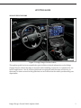
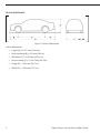
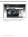
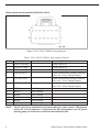
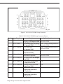
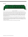
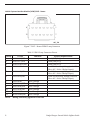
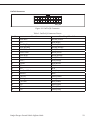
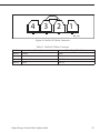
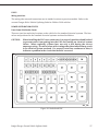
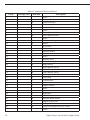
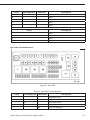
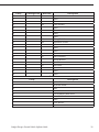
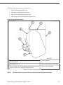
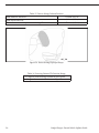
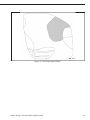
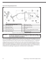
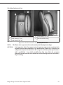
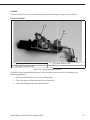
2011 - 2015
Dodge Charger
Pursuit Vehicle
Upfitter Guide
SAFETY NOTICE
This publication’s purpose is to provide technical training information to individuals in the
automotive trade. All test and repair procedures must be performed in accordance with
manufacturer’s service and diagnostic manuals. All warnings, cautions, and notes must be
observed for safety reasons. The following is a list of general guidelines:
• Proper service and repair is critical to the safe, reliable operation of all motor vehicles.
• The information in this publication has been developed for service personnel, and can help
when diagnosing and performing vehicle repairs.
• Some service procedures require the use of special tools. These special tools must be used as
recommended throughout this Technical Training Publication, the diagnostic manual, and the
service manual.
• Special attention should be exercised when working with spring- or tension-loaded
fasteners and devices such as E-Clips, Cir-clips, snap rings, etc. Careless removal may cause
personal injury.
• Always wear safety goggles when working on vehicles or vehicle components.
• Improper service methods may damage the vehicle or render it unsafe.
• Observe all warnings to avoid the risk of personal injury.
• Observe all cautions to avoid damage to equipment and vehicles.
• Notes are intended to add clarity and should help make your job easier.
Cautions and warnings cover only the situations and procedures Chrysler Group LLC has
encountered and recommended. Neither Chrysler Group LLC nor its subsidiaries or af�iliates
cannot know, evaluate, and advise the service trade of all conceivable ways in which service may
be performed, or of the possible hazards for each. Consequently, Chrysler Group LLC and its
subsidiaries and af�iliates have not undertaken any such broad service review. Accordingly,
anyone who used a service procedure or tool that is not recommended in this publication, must be
certain that neither personal safety, nor vehicle safety, is jeopardized by the service methods they
select.
No part of this publication may be reproduced, stored in a
retrieval system or transmitted, in any form or by any
means, electronic, mechanical, photocopying, recording,
or otherwise, without the prior written permission of
Chrysler Group LLC.
Chrysler Group LLC reserves the right to make changes
from time to time, without notice or obligation, in prices,
speci�ications, colors and materials, and to change or
discontinue models. See your dealer for the latest
information.
Copyright © 2014 Chrysler Group LLC
UPFITTER GUIDE
VEHICLE SPECIFICATIONS
407_701
Figure 1 Dodge Charger Pursuit Vehicle
This up itter guide has been assembled to give facilities technical information on the Dodge
Charger Pursuit vehicle that may be required when installing accessories or equipment for use
in leet applications. Not all vehicles purchased are equipped with the same accessories, so
there may be items covered in this guide that are not featured on the vehicle purchased by your
department.
Dodge Charger Pursuit Vehicle Upϔitter Guide
1
VEHICLE DIMENSIONS
407_702
Vehicle Dimensions
•
Length (A) = 5,077 mm (199.9 in.)
•
Front overhang (B) = 924 mm (36.4 in.)
•
Height (E) = 1,491 mm (58.7 in.)
•
•
•
2
Figure 2 Vehicle Dimensions
Wheelbase (C) = 3,052 mm (120.2 in.)
Rear overhang (D) = 1,101.5 mm (43.4 in.)
Width (F) = 1,904 mm (75.0 in.)
Dodge Charger Pursuit Vehicle Upϔitter Guide
CHRYSLER FLEET WEBSITE
407_703
Figure 3 Chrysler Fleet Website
The Chrysler Fleet website is another resource for up-to-date speci ication information on
the Dodge Charger Pursuit and other leet vehicles. An electronic copy of additional up itter
information, as well as options and service recommendations, are also found at
www. leet.chrysler.com.
Dodge Charger Pursuit Vehicle Upϔitter Guide
3
Vehicle Systems Interface Module (VSIM) 2011–2014.5
6
1
12
7
407_750
Figure 4 2011–2014.5 VSIM 12-way Connector
Table 1 2011–2014.5 VSIM 12-way Connector Pinout
Cavity
1
2
3
4
Circuit
A100 16 RD/WHT
A101 16 VT/RD
A102 16 WHT/RD
F100 16 PK/VT
6
F102 16 WHT/PK
5
7
8
9
10
11
12
NOTE:
4
Function
F101 16 VT/PK
BK/TN
BK/WT
BK/OR
BK/GR
BK/RD
BK/BL
Pass Through
Pass Through
Pass Through
Pass Through
Pass Through
Pass Through
Upϐitter Requirements
Fused (20A) B (+)
Fused (20A) B (+)
Fused (20A) B (+)
Fused 20A accessory Voltage (with IGN
ON or ACC - Police 1 Relay Output)
Fused 20A accessory Voltage (with IGN
ON or ACC - Police 3 Relay Output)
Fused 20A accessory Voltage (with IGN
ON or ACC - Police 2 Relay Output)
The 12- and 24-way connectors are located under the center console. The opposite
end of the 12-way connector is found near the RH front bumper near the power
steering pump, or attached to a stud near the underhood PDC.
Dodge Charger Pursuit Vehicle Upϔitter Guide
4
1
10
5
18
11
24
19
407_751
Figure 5 2011–2014.5 VSIM 24-way Connector
Cavity
1
2
3
Table 2 2011–2014.5 VSIM 24-way Connector Pinout
Circuit
W500 20BR/OR
Function
Front lashing lights
(WigWags) 12V input to VSIM
W501 20BLK
Rear lashing lights (WigWags)
12V input to VSIM
W511 20BR/WT Police radio input
Upϐitter Requirements
None - current limiting resistor is
internal to VSIM
None - current limiting resistor is
internal to VSIM
None - current limiting resistor is
internal to VSIM
W513 20BR/GY
None - current limiting resistor is
internal to VSIM
4
W512 20BR/VT
6
W514 20BR/YL
5
7
W515 20BR/LB
8
W516 20BR/DB
10
W518 20BR/DG
9
W517 20BR/LG
12V input to VSIM
Brake lamp switch sense 10V
output from VSIM
Horn switch sense 9V output
when horn is pressed
P/N switch sense 10V Output
from VISM
VTSS/Panic alarm ON signal
9V Output from VSIM
Headlamp switch sense 10V
Output from VSIM
Side airbag status signal 12V
Output from VSIM when
airbag deploys
Front airbag status signal 12V
Output from VSIM when
airbag deploys
Dodge Charger Pursuit Vehicle Upϔitter Guide
N/A
N/A
N/A
N/A
N/A
5
Cavity
11
12
13
14
15
16
17
18
19
Circuit
Function
W530 20BR/DG VSIM CAN-B bus (+)
W531 20BR/LG VSIM CAN-B bus (-)
W521 20BR/WT Cluster dimming sense 12V
Output from VSIM
W522 20BR/VT Engine running signal 10V
Output from VSIM
W523 20BR/GY Driver door ajar switch sense
10V Ouput from VSIM with
door open
Z384 20BK
Signal ground that is noise
suppressed
NOT USED
NOT USED
NOT USED
W526 20BR/DB
20
W536 20BR/YL
21
W537 20BR/VT
23
W539 20BR/DB
24
W540 20BR/DG
22
6
W538 20BR/OR
NOT USED
Vehicle speed signal 12V
10 Hz/mph pulse-width
modulated
Horn mute signal 12V, 20 mA
Input to VSIM disables horn
function
VTSS mute signal 12V, 20 mA
Input to VSIM
Fuel level status signal 12V
PWM Output
Driver seatbelt switch sense
10V Output from VSIM when
buckled
MIL Malfunction indicator
lamp 9V Output from VSIM
when MIL is on
Upϐitter Requirements
N/A
N/A
N/A
N/A
N/A
N/A
N/A
N/A
N/A
NONE - Current limiting resistor is
internal to the VSIM
NONE - Current limiting resistor is
internal to the VSIM
N/A
N/A
N/A
Dodge Charger Pursuit Vehicle Upϔitter Guide
2015 VSIM
Figure 6 2015 VSIM
The microcontroller-based electronic Vehicle System Interface Module (VSIM) (also known as
the Vehicle Systems Integration Module/VSIM or the aftermarket module) contains the electronic
logic circuitry and software that enable many of the aftermarket equipment and systems typically
installed on police or leet vehicles to communicate with and be integrated with the electronic
control modules and features already installed in the vehicle. The VSIM can communicate with
aftermarket modules or with other electronic modules in the vehicle using the Controller Area
Network (CAN) C data bus.
The VSIM is powered by a fused B(+) circuit and is grounded at all times so that it can operate
regardless of the ignition switch position. The module awakens or sleeps based upon the status
of the CAN C data bus network. The module monitors both active and stored Diagnostic Trouble
Codes (DTC) through On-Board Diagnostics (OBD) and communicates with a diagnostic scan tool
using the CAN C data bus.
The VSIM is located under the LH side of the instrument panel assembly.
Dodge Charger Pursuit Vehicle Upϔitter Guide
7
Vehicle Systems Interface Module (VSIM) 2015 - Newer
6
1
12
7
407_750
Figure 7 2015 - Newer VSIM 12-way Connector
Cavity
1
2
3
4
Circuit
A100 16 RD/VT
A101 16 VT/RD
A102 16 WHT/RD
F100 16 PK
6
F103 16 PK/DB
5
7
8
9
10
11
12
NOTE:
8
Table 3 VSIM 12-way Connector Pinout
Function
F103 16 PK/GY
Z384 18 BK
P239 18 LG/WT
P820 18 BR/OR
P822 18 BR/WT
W507 18 OR
W508 18 OR/BR
Pass Through
Pass Through
Pass Through
Pass Through
Pass Through
Pass Through
Upϐitter Requirements
Fused (20A) B (+)
Fused (20A) B (+)
Fused (20A) B (+)
Fused 20A accessory Voltage (with IGN
ON or ACC - Police 1 Relay Output)
Fused 20A accessory Voltage (with IGN
ON or ACC - Police 3 Relay Output)
Fused 20A accessory Voltage (with IGN
ON or ACC - Police 2 Relay Output)
Mating connector/pigtail 68251805AA
Dodge Charger Pursuit Vehicle Upϔitter Guide
Vehicle Systems Interface Module (VSIM) 2015
Figure 8 2015 - Newer VSIM 24-way C1 Connector (Grey)
Cavity
Circuit
1
W561 18 LG/BR
2
W562 18 LG/VT
3
4
5
6
7
8
NC
NC
NC
NC
NC
W563 18 LG/DB
9
W734 18 PK/GY
10
W736 18 PK/YL
11
W720 20 VT/OR
12
G745 20 VT/WT
Table 4 VSIM 24-way C1 Connector Pinout
Function
Steering Wheel Switch
1
Steering Wheel Switch
2
Future Use
Future Use
Future Use
Future Use
Future Use
Steering Wheel Switch
3
Type
High-side
driver, Pulled
down
High-side
driver, Pulled
down
High-side
driver, Pulled
down
Up itter Ignition Run/ Low-side
Accy 2
driver, Pulled
up
Up itter Ignition Run
Low-side
driver, Pulled
up
Up itter Any Door Ajar Low-side
driver, Pulled
up
Police VISM Inline:
Low-side
Right Front Passenger driver, Pulled
Door Ajar
up
Dodge Charger Pursuit Vehicle Upϔitter Guide
Upϐitter Requirements
12V Digital output, low
current
12V Digital output, low
current
12V Digital output, low
current
9
Cavity
Circuit
13
G776 20 VT/YL
14
15
16
17
NC
NC
NC
NC
20
W522 18 OR/WT
21
W702 20 DG/DB
22
W703 20 DG/LB
23
K682 20 DB/WT
24
NC
18
19
NC
G755 20 VT/GY
Function
Police VISM Inline:
Right Rear Door Ajar
Future Use
Future Use
Future Use
Future Use
Type
Low-side
driver, Pulled
up
Upϐitter Requirements
Future Use
Police VISM Inline: Left Low-side
Rear Door Ajar
driver, Pulled
up
Engine Running/Hour High-side
Meter
driver, Pulled
down
Up itter Trans Reverse Low-side
Position
driver, Pulled
up
Up itter Trans Drive
Low-side
Position
driver, Pulled
up
Police VISM Inline: Any Low-side
Door Ajar
driver, Pulled
up
NOTE:
Mating connector/pigtail 68213591AAA
NOTE:
A high-side driver provides a voltage source in most cases to a relay control circuit.
A low-side driver provides a ground to a relay or lamp circuit for control.
10
Dodge Charger Pursuit Vehicle Upϔitter Guide
4
1
10
5
18
11
24
19
407_751
Figure 9 2015 - Newer VSIM 24-way C2 Connector (White)
Cavity
1
2
3
4
5
Table 5 VSIM 24-way C2 Connector Pinout
Circuit
Function
W500 18 BR/OR Front lashing lights
(WigWags) 12V input to
VSIM
W501 18 BR/VT Rear Wig Wag Switch
Signal 12V input to VSIM
W640 18 BR/WT Up itter Audio Switch
Mute Signal
W726 18 BR/VT Up itter Brake Pedal
Depressed
W513 18 BR/GY
Horn Activation
6
W700 20 BR/YL
7
W515 18 BR/LB
Up itter Trans Park
Position
8
W516 18 BR/DB Headlamps ON Strobe
Panic Alarm Activation
Dodge Charger Pursuit Vehicle Upϔitter Guide
Type
Upϐitter Requirements
N/A
N/A
High-side
driver, Pulled
down
High-side
driver, Pulled
down
High-side
driver, Pulled
down
High-side
driver, Pulled
down
High-side
driver, Pulled
down
N/A
N/A
N/A
N/A
N/A
N/A
11
Cavity
9
10
11
12
13
14
15
16
17
18
19
20
21
22
23
24
NOTE:
12
Circuit
W524 18 BR/LG
Function
Vehicle Speed Transmit
Type
Upϐitter Requirements
High-side
N/A
driver, Pulled
down
W553 18 BR/DG Stealth Mode Active
High-side
N/A
driver, Pulled
down
W532 22 BR/DG Up itter Side CAN-IHS (+)
N/A
W534 22 BR/LG Up itter Side CAN-IHS (-)
N/A
N/A
W552 18 BR/WT Cluster Dimming Active
High-side
Signal
driver, Pulled
down
W522 18 BR/VT Engine Running/Hour
High-side
N/A
Meter
driver, Pulled
down
W523 18 BR/GY Driver Door Ajar
High-side
N/A
driver, Pulled
down
Z910 18 BK
Police VISM Inline Ground
N/A
K684 20 DB/YL Police VISM Inline
Not
N/A
Currently
Used
K686 20 DB/WT Police VISM Inline
Not
N/A
Currently
Used
W526 18 BR/DB Vehicle Speed Return
High-side
N/A
Signal
driver, Pulled
down
W536 18 BR/YL Horn Switch Mute
N/A
W537 18 BR/OR Panic Alarm Switch Mute High-side
N/A
Signal
driver, Pulled
down
NC
N/A
W710 18 BR/DB Up itter Seat Belt Not
High-side
N/A
Latched
driver, Pulled
down
W540 20 BR/DG MIL Lamp ON
High-side
N/A
driver, Pulled
down
Mating connector/pigtail 68251804AA
Dodge Charger Pursuit Vehicle Upϔitter Guide
VSIM Connectors for Upfiƫng (2015 - Newer)
1
2
3
L10_000
1
2
24-way C2 (White)
24-way C1 (Grey)
3
12-way
Figure 10 VSIM Interface Connectors
The VSIM up itter connectors are located under the center console. The two 24-way connectors
are located close to the bottom of the instrument panel, while the 12-way connector is located next
to the mounting bolt for the console.
NOTE:
There are sensors for the keyless entry system and antilock brake system located
under the console. Make sure during upϐit that the sensors are not repositioned.
Sensor placement is critical for proper system operation.
Dodge Charger Pursuit Vehicle Upϔitter Guide
13
12-Way Connector Terminals
407-323
Figure 11 12-Way Pigtail Location
The opposite end of the 12-way connector (terminals 7-12) are located under the hood, next to the
power distribution center.
14
Dodge Charger Pursuit Vehicle Upϔitter Guide
STEERING WHEEL SWITCHES Έ2015 ͳ NEWERΉ
Auxiliary Switches
Figure 12 Auxiliary Switches
The auxiliary switch assembly is part of the right steering wheel switch pod, which also housed the
speed control switches. The switch assembly is connected to the steering column control module,
which is part of the steering column assembly. The switches communicate to the steering column
control module through a local interconnect network (LIN). The switches provide an input to the
vehicle systems interface module (VSIM) which provides a 12V digital output (low current) to the
up itter connector, mounted under the center console.
The switches are not serviceable, and must be replaced as an assembly if damaged. Information
on each switches output is located in the chart in this section.
Dodge Charger Pursuit Vehicle Upϔitter Guide
15
LIGHTING
Police Dome Light
407_727
Figure 13 Police Dome Light
The police dome light switch has three positions. Position one is used for white light, position two
is used for red LED light, and position three is OFF. When the dome light is not needed, always
remember to return the dome light switch to the OFF (center) position to prevent the vehicle
battery from discharging.
16
Dodge Charger Pursuit Vehicle Upϔitter Guide
Spot Light
407_728
Figure 14 Spot Light
The spot light connector is located at the leading edge of the headliner near the A-pillars.
CAUTION:
Make sure the airbag tether is correctly fastened in place.
Stealth Mode
This vehicle is designed for periods of surveillance. The dimmer control is located next to the
headlight switch, on the left side of the instrument panel. By rotating the dimmer control to the
extreme OFF position (to stealth mode), all interior illumination, except for the EVIC display on
the IPC, backlighting for the door switches, and the vehicle critical warning indicators, will be
eliminated. The EVIC display and the warning indicators will go to the lowest legal limit.
The courtesy (interior) lights are disabled when opening the door and will operate only by rolling
the headlight dimmer switch to the fully upward (detent) position, or by pressing each map light
individually.
Dodge Charger Pursuit Vehicle Upϔitter Guide
17
PROGRAMMING
Grille, Visor, Side, and Rear Deck Lights
NOTE:
Prior to programming ϐlash patterns, the lighthead must be on and activated.
When using Scan-Lock™ (WHT/VIO), advance to the next pattern by applying +VDC to the WHT/
VIO wire for less than one second.
To cycle backwards, apply +VDC for more than one second.
To reset to the factory default pattern, turn off power to the lighthead. While applying +VDC to the
WHT/VIO, turn the lighthead back on. Continue to apply voltage for ive seconds.
Lightheads con igured to display the Phase 1 mode of a pattern will lash simultaneously. Any
lightheads con igured to display the Phase 2 mode will alternate with any Phase 1 lightheads with
the same pattern.
To sync two lightheads, con igure both lightheads to display the same Phase 1 pattern. With
the power off, connect the GRAY wires from each lighthead together. When the lightheads are
activated, their patterns will be synchronized. To con igure the two lightheads to alternate their
patterns, advance the pattern of either lighthead to the Phase 2 mode of the current pattern. The
same concept applies to Phases 3 and 4.
To understand how to use the Sync feature with more than two lightheads, the principles will
be applied to a sample system consisting four lightheads with two mounted on the rear driver
side and two mounted on the rear passenger side. With all the wiring complete, turn on all four
lightheads. As shipped from the factory, the lightheads will all display: SignalAlert™ 75 – Phase 1.
To con igure one side to alternate with the other side, change the pattern for either the passenger
or driver side to Phase 2 mode for that pattern.
18
Dodge Charger Pursuit Vehicle Upϔitter Guide
Table 6 Rear Deck Lights Flash Patterns and Sync Table Patterns
1
2
3
4
5
6
7
8
9
10
11
12
13
14
15
16
17
18
19
20
Flash Patterns
SignalAlert™ 75
SignalAlert™ 75
CometFlash™ 75
CometFlash™ 75
DoubleFlash™ 75
DoubleFlash™ 75
SingleFlash™ 75
SingleFlash™ 75
ComAlert™ 75
ComAlert™ 75
LongBurst™ 75
LongBurst™ 75
PingPong™ 75
PingPong™ 75
Single Flash™ 60
Single Flash™ 60
Single Flash™ 90
Single Flash™ 90
Single Flash™ 120
Single Flash™ 120
Dodge Charger Pursuit Vehicle Upϔitter Guide
Sync
PH1
PH2
PH1
PH2
PH1
PH2
PH1
PH2
PH1
PH2
PH1
PH2
PH1
PH2
PH1
PH2
PH1
PH2
PH1
PH2
19
Front, Rear, and Corner Lights
NOTE:
Prior to programming ϐlash patterns, the lighthead must be on and activated.
To Change PaƩern
To advance to the next pattern, apply +12VDC to the WHITE wire for less than one second and
release. To cycle back to the previous pattern, apply +12VDC to the WHITE wire for more than one
second and release.
To Change the Default PaƩern
When the desired pattern is displayed, allow it to run for more than ive seconds. The lighthead
will display this pattern when initially activated.
To Restore the Factory Default PaƩern
With the light turned off, apply power to the WHITE wire. With power applied to the WHITE wire,
turn the light on. Allow the unit to run for three seconds before removing power from the WHITE
wire.
Sync
To sync two or more lightheads, con igure all lightheads to display the same Phase 1 pattern.
Turn the lightheads off and connect the GREY wires coming from the lightheads together. When
the lightheads are activated, the patterns displayed will be synchronized. To con igure speci ic
lightheads to alternate their patterns with other lightheads, advance the pattern of either lighthead
to Phase 2 of the current pattern.
20
Dodge Charger Pursuit Vehicle Upϔitter Guide
Table 7 Corner Lights Flash Patterns and Sync Patterns
Flash Patterns
SignalAlert™ 75
SignalAlert™ 75
CometFlash™ 75
CometFlash™ 75
DoubleFlash™ 75
DoubleFlash™ 75
SingleFlash™ 75
SingleFlash™ 75
ComAlert™
ComAlert™
LongBurst™
LongBurst™
PingPong™
PingPong™
1
2
3
4
5
6
7
8
9
10
11
12
13
14
Sync
PH1
PH2
PH1
PH2
PH1
PH2
PH1
PH2
PH1
PH2
PH1
PH2
PH1
PH2
Table 8 Corner Lights Flash Patterns and Non-Sync Patterns
15
16
17
18
19
20
21
22
23
24
Flash Patterns
SingleFlash™ 90
SingleFlash™ 90
SingleFlash™ 90
DoubleFlash™ 150
ComAlert™ 150
ActionFlash™ 1
Action lash™ 2
ModuFlash™
ActionScan™
Steady
Dodge Charger Pursuit Vehicle Upϔitter Guide
21
CANTROL MODULE
1
407_725
Figure 15 CanTrol Module Location
The added electrical system can include an auxiliary power distribution center, wiring harness,
CanTrol module, and lights.
The CanTrol module is a state-of-the-art, emergency lighting and siren system that utilizes a
computer-controlled system of relays for switching. The CanTrol module communicates with the
VSIM to determine light operation. These systems do not communicate with the vehicle’s bus,
but may use information provided by the VSIM to operate pre-programmed outputs, depending
on how the vehicle is con igured. If the vehicle is only equipped with a lightbar, it does not use a
CanTrol module, but uses a separate controller installed by the municipality.
22
Dodge Charger Pursuit Vehicle Upϔitter Guide
CanTrol Connectors
10 9 8 7
6 5 4
3 2 1
20 19 18 17 16 15 14 13 12 11
407_729
Figure 16 CanTrol J4 Connector
Position
1
2
3
4
5
6
7
8
9
10
11
22
13
14
15
16
17
18
19
20
Table 9 CanTrol J4 Connector Pinout
Function
Horn Mute
N/A
Rear WigWag
Front WigWag
Tail LED +
Corner LED +
Grille LED +
Mirror LED +
Visor +
B-pillar
N/A
N/A
Rear Deck Flash
Gunlock
T/A Left
T/A Right
T/A Flash
N/A
N/A
N/A
Dodge Charger Pursuit Vehicle Upϔitter Guide
Base Prep Wire Color
Brown/Yellow
Red/White
Brown/Violet
Brown/Orange
Red/Blue
Black/Green
Black/Orange
Red/White
Red/Orange
Red/Brown
White
N/A
Red/Gray
Blue
White/Black
Orange
Blue/White
White/Blue
White/Violet
White/Gray
23
3 2 1
407_730
Figure 17 CanTrol J17 Connector Pinout
Position
Siren 1 Speaker Hi
Siren 2 N/A
Siren 3 Speaker Lo
24
Table 10 CanTrol J17 Connector Pinout
Function
Base Prep Wire Color
Black/Tan
N/A
Black/White
Dodge Charger Pursuit Vehicle Upϔitter Guide
4
3
2
1
407_731
Figure 18 CanTrol J17 Molex Connector
Position
Molex 1
Molex 2
Molex 3
Molex 4
Table 11 CanTrol J17 Molex Connector
Function
Ground
Ground
Power
Power
Dodge Charger Pursuit Vehicle Upϔitter Guide
Base Prep Wire Color
Black
Black
Red X 2
Red X 2
25
8
16
7
6
15 14
5
4
13 12
3
2
1
11 10
9
407_732
Figure 19 CanTrol J17 16 Pin Connector
Position
1
2
3
4
5
6
7
8
9
10
11
12
13
14
15
16
26
Table 12 CanTrol J17 16 Pin Connector
Function
N/A
Head Light Sense
Park/Neutral Sense
Horn Sense
N/A
N/A
Ignition Sense
N/A
N/A
N/A
N/A
Alarm Sense
Driver Door Ajar
N/A
N/A
N/A
Base Prep Wire Color
White/Brown
Brown/Blue
Brown
Brown/Gray
White/Black
White/Violet
Orange/Violet
Blue
Black/White
White/Green
White
Brown/Blue
Brown/Gray
N/A
N/A
Blue
Dodge Charger Pursuit Vehicle Upϔitter Guide
FUSES
Wiring provisions
The wiring take outs and connections are in similar locations as previous models. Refer to the
current Charger Police Vehicle Up itting Guide for 2006 to 2010 vehicles.
POWER DISTRIBUTION CENTER
Front Power DistribuƟon Center
There are two fuse and relay locations on the vehicle for the standard electrical systems. The fuse
values and positions for the standard electrical systems are described below.
CAUTION:
When installing the PDC cover, make sure it is properly positioned and latched
to prevent water from getting into the PDC and causing an electrical system
failure. When replacing a blown fuse, use only a fuse having the correct
amperage rating. The use of a fuse with a rating other than indicated may result
in an electrical system overload. If a properly rated fuse continues to blow, it
indicates a problem in the circuit that must be corrected.
407_706
Figure 20 Underhood PDC
Dodge Charger Pursuit Vehicle Upϔitter Guide
27
Cavity
1
2
3
4
5
6
7
8
9
10
11
12
13
14
15
16
18
19
20
21
22
23
24
28
29
30
31
32
33
34
35
36
37
38
39
48
28
Table 13 Underhood Fuses and Relays
Cartridge Fuse
Mini-fuse
40
50
30
20
20
20
10
20
10
25
50
50
30
20
20
20
20
25
15
25
25
20
10
10
10
10
Description
Spare
Radiator Fan 1
Power Steering 1
Starter
Antilock Brakes
Spare
Police Ignition Feed 1
Police Ignition Feed 2
Spare
Underhood Lamp
Horns
A/C Clutch
Spare
Antilock Brakes
Spare
Spare
Radiator Fan 2
Power Steering 2
Wiper Motor
Police Battery Feed 3
Police Battery Feed 2
Police Battery Feed 1
Police Ignition Feed 3
Fuel Pump
Transmission
Spare
Engine Module
Spare
Spare
ASD Feed 1
ASD Feed 2
Antilock Brake Module
Engine Control/Fan
Airbag Module
Power Steering Module/A/C Clutch
Spare
Dodge Charger Pursuit Vehicle Upϔitter Guide
Cavity
Cartridge Fuse
49
50
51
52
53
Mini-fuse
Description
Spare
Spare
Vacuum Pump
Spare
Spare
Relays
20
Cavity
Description
Spare
Vacuum Pump
Spare
Starter
17
25
26
27
Rear Power DistribuƟon Center
407_704
Figure 21 Rear PDC
Cavity
2
3
4
5
6
Table 14 Rear PDC Fuses and Relays
Cartridge Fuse
60
Mini-fuse
60
20
40
Dodge Charger Pursuit Vehicle Upϔitter Guide
Description
Front PDC Feed 1
Spare
Front PDC Feed 2
Dome Lamp
Exterior Lighting 1
29
Cavity
7
8
9
10
11
12
15
16
17
18
19
20
21
22
23
24
25
26
27
31
32
33
34
35
36
37
38
40
41
42
43
44
45
46
47
48
49
30
Cartridge Fuse
Mini-fuse
40
30
30
30
30
20
40
20
10
15
10
25
15
15
10
10
20
15
30
15
Description
Exterior Lighting 2
Interior Lighting/Washer Pump
Power Locks
Driver Door
Passenger Door
Power Outlets (selectable)
HVAC Blower
Spare
Spare
Spare
Spare
Spare
Spare
Right Spot Lamp
Fuel Door/Diagnostic Port
Radio Screen
Tire Pressure Monitor
Spare
Spare
Power Seats
HVAC Module/Cluster
Ignition Switch/Wireless Module
Steering Column Module/Police Module
Battery Sensor
Left Spot Lamp
Radio
Spare
Spare
Spare
Rear Defrost
Spare
Spare
Cluster/Rearview Mirror
Spare
Spare
Spare
Spare
Dodge Charger Pursuit Vehicle Upϔitter Guide
Cavity
Cartridge Fuse
50
51
52
53
54
55
56
57
58
59
60
61
62
63
64
65
66
67
68
69
70
Mini-fuse
10
10
20
25
10
15
Cavity
1
13
14
28
29
30
39
71
72
Dodge Charger Pursuit Vehicle Upϔitter Guide
Description
Spare
Spare
Spare
HVAC Module
Spare
Spare
Spare
Spare
Airbag Module
Adjustable Pedals
Spare
Spare
Spare
Spare
Rear Windows
Airbag Module
Spare
Run Sense
Spare
Spare
Spare
Relays
Description
Ignition Run
Adjustable Pedals
Spare
Rear Defrost
Rear Windows/Run Sense
Power Outlets
Spare
HVAC Blower
Spare
31
Auxiliary Power DistribuƟon Center
407_705
Figure 22 Auxiliary Power Distribution Center
Cavity
32
F1
F2
F3
F4
F7
F8
F9
F10
F11
F12
F13
F14
F15
F16
F17
F18
F19
Amperage
5
5
5
2
5
5
2
2
2
2
2
2
2
5
5
2
2
Description
Front Corner LEDs
Grill LEDs
Mirror LEDs
Visor Trigger
B Pillar LEDs
Deck LEDs
Takedown
Right Alley
Left Alley
Lightbar Front
Lightbar Rear
Tail Lamp Flash
Headlamp Flash
Rear LEDs
Gun Lock
T/A Left
T/A Right
Dodge Charger Pursuit Vehicle Upϔitter Guide
Cavity
F20
F21
F22
F23
F24
F25
F26
F27
F28
F29
F30
F31
F32
F34
F36
F37
F38
F39
Amperage
2
25
25
25
25
20
20
10
30
15
15
20
5
5
15
10
10
5
Cavity
R1
R2
Dodge Charger Pursuit Vehicle Upϔitter Guide
Description
T/A Flash
Siren In1A
Siren In1B
Siren In2A
Siren In2B
Front Radio
Rear Radio
Radar
Lightbar
Visor
T/A
Siren Controller
Front Radio
Fan/Timer Module Ign
Computer
Camera
Modem
Printer
Relays
Description
Ignition Relay
Horn Relay
33
PASSIVE RESTRAINTS
Occupant Restraint System
WARNING:
WARNING:
WARNING:
WARNING:
INSTALLING A CONVENTIONAL PRISONER PARTITION IS NOT RECOMMENDED
ON VEHICLES EQUIPPED WITH LEFT AND RIGHT SIDE CURTAIN AIRBAGS, AS
POLICE CAGES MAY INTERFERE WITH THE DEPLOYING AIRBAG. THE AREA
WHERE THE SIDE CURTAIN AIRBAG IS LOCATED SHOULD REMAIN FREE
FROM ANY OBSTRUCTIONS. ONLY INSTALL A PARTITION THAT IS DESIGNED
TO BE COMPATIBLE WITH SIDE CURTAIN AIRBAGS.
IF YOUR VEHICLE IS EQUIPPED WITH LEFT AND RIGHT SIDE CURTAIN
AIRBAGS, CARE MUST BE TAKEN WHEN INSTALLING ANY TYPE OF ROOF
EQUIPMENT. DRILLING AND INSTALLATION OF FASTENERS OR OTHER
EQUIPMENT THAT MAY INTERFERE WITH THE SIDE CURTAIN AIRBAGS
AND AIRBAG WIRING HARNESS IS NOT PERMITTED. MAKE SURE THAT NO
EQUIPMENT OR FASTENERS ARE LOCATED IN THE AIRBAG DEPLOYMENT
ZONE.
DO NOT PLACE OBJECTS, OR MOUNT EQUIPMENT, IN FRONT OF THE
AIRBAG MODULE COVER OR IN FRONT OF THE SEAT AREAS THAT MAY
COME IN CONTACT WITH A DEPLOYING AIRBAG. FAILURE TO FOLLOW THIS
INSTRUCTION COULD RESULT IN PERSONAL INJURY.
DO NOT PLACE DASH, TUNNEL, OR CONSOLEǧMOUNTED EQUIPMENT
OUTSIDE OF THE SPECIFIED ZONE. FAILURE TO FOLLOW THIS INSTRUCTION
COULD RESULT IN PERSONAL INJURY.
The occupant restraint system contains the following components:
•
Left front impact sensor
•
Driver side airbag
•
•
•
•
Driver airbag
Passenger airbag
Passenger side airbag
•
Occupant restraint controller (ORC) module
•
Left side impact sensors
•
•
•
34
Right front impact sensor
Driver seatbelt tensioner
Passenger seatbelt tensioner
Right side impact sensors
Dodge Charger Pursuit Vehicle Upϔitter Guide
There are four interior zones to be aware of:
•
•
•
•
Driver airbag deployment zone
Passenger airbag deployment zone
Side curtain airbags deployment zone
Side airbags (seat-mounted) deployment zone
Driver Airbag Deployment Zone
407_708
1 Vertical Plane Passing Through the Center of the
4 Steering Wheel
Steering Wheel
2 475 mm (18.7 in.)
5 Driver Airbag Retainer/Housing
3 Vertical Plane Passing Through the Maximum Rearward 6 Driver Airbag Cushion
Point that the Driver Airbag Cushion Reaches
NOTE:
Figure 23 Driver Airbag Dimensions
The illustration represents the maximum dynamic deployment shape.
Dodge Charger Pursuit Vehicle Upϔitter Guide
35
Table 15 Driver Airbag Cushion Position
DAB diameter when full
DAB depth when full
Maximum rearward displacement during ill
673 mm (26.5 in.)
381 mm (15 in.)
470 mm (18.5 in.)
407_709
Figure 24 Driver Airbag Deployed Shape
Table 16 Steering Column Tilt Position Range
± 2.7 degrees from steering column tilt pivot point
21.0 degrees from vertical is the normal position
36
Dodge Charger Pursuit Vehicle Upϔitter Guide
2
1
407_710
1
Driver Seating Reference
Driver Airbag Cushion Lateral
Deployment Zone 711 mm (28 in.)
Figure 25 Deployment Zone
Dodge Charger Pursuit Vehicle Upϔitter Guide
2
37
407_711
1
2
3
NOTE:
38
Passenger Airbag Cushion
Vertical Plane from Point of Instrument
Panel
4
5
Instrument Panel
Vertical Plane Passing Through the
Maximum Rearward Point That the
Passenger Airbag Cushion Reaches
Passenger Airbag Module
6
470 mm (18.5 in.)
Figure 26 Passenger Airbag Deployment Zone
The illustration represents the maximum dynamic deployment shape.
Dodge Charger Pursuit Vehicle Upϔitter Guide
407_712
Figure 27 Final Deployment Shape
Dodge Charger Pursuit Vehicle Upϔitter Guide
39
407_713
1
2
40
70 mm (2.75 in.)
3
508 mm (20.0 in.)
Passenger Airbag Deployment Zone
4
Reference Point
Figure 28 Deployment Zone
Dodge Charger Pursuit Vehicle Upϔitter Guide
407_714
WARNING:
NOTE:
Figure 29 Center Interior Area
MAKE SURE ADEQUATE SPACE IS AVAILABLE FOR AIRBAG DEPLOYMENT.
MOUNTING ACCESSORIES AND EQUIPMENT INSIDE THE DEPLOYMENT
ZONES IMPEDES AIRBAG DEPLOYMENT.
The illustration represents the maximum dynamic deployment shape.
Dodge Charger Pursuit Vehicle Upϔitter Guide
41
Side Curtain Airbag Deployment Zone
407_715
1
2
3
4
5
6
Cross Sectional Area Side View
220.9 mm (8.7 in.)
88.9 mm (3.5 in.)
449.6 mm (17.7 in.)
1033.8 mm (40.7 in.)
502.9 mm (19.8 in.)
WARNING:
7
8
9
10
11
12
88.9 mm (3.5 in.)
368.3 mm (14.5 in.)
482.6 mm (16.0 in.)
B-pillar
Side Curtain Airbag In lator Module
88.9 mm (3.5 in.)
Figure 30 Side Curtain Airbag Deployment Zone
MAKE SURE ADEQUATE SPACE IS AVAILABLE FOR AIRBAG DEPLOYMENT. DO
NOT MOUNT EQUIPMENT OR ROUTE WIRES IN A WAY THAT WILL IMPEDE
SIDE CURTAIN AIRBAG DEPLOYMENT.
If the vehicle is equipped with side curtain airbags, take care when installing equipment in the roof
area to avoid drilling or installing fasteners in the side curtain airbag area. Also make sure that no
equipment installed inside the vehicle interferes with the airbag deployment areas. If additional
wiring needs to be routed on the sides of the roof, take care that the installed harness does not
impede the airbag deployment. Point fasteners used to attach roof-mounted equipment outward
from the passenger compartment to minimize risk of head injury and to avoid altering the head
impact protection system (FMVSS 201) that is standard on these vehicles. Do not allow fasteners
to extend into the passenger compartment, even between the roof and headliner.
42
Dodge Charger Pursuit Vehicle Upϔitter Guide
Side Airbag Deployment Zone
407_716
1
2
3
NOTE:
Front Driver Seat
4495.8 mm (177 in.)
1998.9 mm (78.7 in.)
4
5
1998.9 mm (78.7 in.)
Seat-mounted Airbag
Figure 31 Side Seat-mounted Airbag Deployment Zone
The illustration represents the maximum dynamic deployment shape.
CAUTION:
It is imperative that all occupant restraint system components remain in their
original location and orientation. Any modiϐication, removal, or relocation of
components may be detrimental to the occupant restraint system performance
and is prohibited. Any vehicle modiϐication that may affect the occupant
restraint system characteristics should be veriϐied through vehicle calibration/
impact testing.
Dodge Charger Pursuit Vehicle Upϔitter Guide
43
Occupant Restraint System Wiring
All occupant restraint system wiring must remain intact and may not be used for any other
purpose. This includes the driver and front passenger seat wiring. Any electrical connector that
is yellow is part of the occupant restraint system and should not be modi ied or used for other
purposes.
Occupant Restraint System VerificaƟon
After any modi ication work is complete, con irm the occupant restraint system readiness as
follows: turn the ignition key to the ON position. The airbag lamp in the instrument cluster
illuminates for 6 to 8 seconds, and then turns off. If the airbag lamp fails to illuminate, repeatedly
cycles on and off, or does not turn off, have the condition corrected by an authorized Chrysler LLC
dealership before shipping the vehicle to the customer.
44
Dodge Charger Pursuit Vehicle Upϔitter Guide
TOWING
Chrysler Group LLC does not recommend towing with the Dodge Charger Pursuit vehicle.
VEHICLE STORAGE
1
2
3
407_717
1
2
Clamping Nut (do not remove)
3
Negative Battery Cable
Ground Connection Nut
Figure 32 Intelligent Battery Sensor
If a vehicle is not immediately delivered to the customer, store the vehicle according to the
following guidelines:
•
•
•
Store the vehicle indoors, in a clean and dry place.
Check the engine coolant and anti-freeze protection.
Leave the parking brake in the OFF position.
Dodge Charger Pursuit Vehicle Upϔitter Guide
45
If vehicles must be stored outside:
•
Avoid storage locations near obvious sources of industrial or environmental contamination
(such as trees, factories, steam or vapor vents, railroad tracks, etc.).
•
If the vehicle must be parked on an incline, park it with the front end higher than the rear.
This prevents hydrostatic lock caused by fuel draining into the engine.
•
Maintain tight security to help prevent vandalism. Inspect the vehicle regularly to check for
such damage.
•
Rinse the vehicle at least once a week. Wash away the snow more often because it can trap
harmful contaminants. Dry all horizontal surfaces.
•
Keep all windows closed, all doors locked, and all trim covers intact and in place.
•
Use protective, thin, plastic ilm to avoid soiling seats when moving a vehicle.
•
•
NOTE:
Remove the negative battery cable by removing the ground connection nut to prevent
battery drain and possible damage.
Do not use chalk, crayon, or any marker containing abrasives on painted, plated, or glass
surfaces.
The 2011 and newer Dodge Charger Pursuit vehicle does not have an IOD fuse as in
previous models. Therefore, the negative battery cable should be removed from the
intelligent battery sensor to prevent draining the battery during extended vehicle
storage. Only loosen the ground connection nut from the intelligent battery sensor
to remove the negative battery cable.
WARNING:
THE BATTERY IN THIS VEHICLE HAS A VENT HOSE THAT SHOULD NOT BE
DISCONNECTED AND SHOULD ONLY BE REPLACED WITH A BATTERY OF THE
SAME TYPE ȍVENTEDȎ. FAILURE TO FOLLOW THIS WARNING CAN RESULT IN
SERIOUS OR FATAL INJURY.
Once a month:
•
•
•
46
Check the battery state for charge (at least 12.4 volts). Charge the battery as necessary to
help prevent freezing and deterioration.
Make sure that the battery vent tube is properly connected to the battery and to the loor
pan.
Check the vehicle tire pressures and in late them to the maximum recommended levels. To
help avoid lat spotting, move the vehicle at least once a month so that a different portion of
the tire tread contacts the ground.
Dodge Charger Pursuit Vehicle Upϔitter Guide
VEHICLE STORAGE
Shipping Mode
The Dodge Charger Pursuit vehicle no longer uses an IOD fuse when transporting or storing for
a long period of time. The BCM has a Shipping Mode that takes the place of pulling the IOD fuse.
The vehicle will come from the factory in Shipping mode.
To enable/disable the Shipping Mode function:
•
•
2011-2014 - Press and hold the Front Defrost and Enter/Browse for ive seconds. You can
also enable/disable the vehicle from Shipping Mode by using the scan tool: go to BCM then
Misc. function.
2015 - Newer - Turn the ignition ON (No engine cranking or running required)
–
–
–
–
Turn on the hazard lamps (also known as emergency lashers)
Press the “Up Arrow” button on the left steering wheel button pod and hold for 5
seconds
Mode is switched from “Shipping Mode” to “Customer Mode”
Turn off the hazard lamps
Description
Keep all protective
transit ilm, wheel
covers, and ilms on
vehicle
In late the tire pressure
to the maximum side
wall pressure
Put the vehicle into
Ship Mode (if no IOD
fuse)
NOTE:
Table 17 Vehicle Storage
Action
Keep all protective transit ilm, wheel covers, and ilms on vehicle until
sold.
In late the tire pressure to the maximum side wall pressure (except
heavy duty trucks).
See instructions above
Vehicle may not be returned to Ship Mode if the vehicle has over 110 miles on the
odometer.
Dodge Charger Pursuit Vehicle Upϔitter Guide
47
TRUNK COOLING FAN
407_710
Figure 33 Trunk Cooling Fan
The trunk cooling fan is driven by the necessity to either heat or cool the trunk area when
equipment is installed in the trunk. Previous models of camera systems contained a vault that
had its own environmental controls, but (with the arrival of digital recording) most of these went
away. Multi-piece computers or laptops have been moved to the trunk area and this has caused
the systems to either freeze in cold climates or become overheated in warm climates. The trunk
fan helps to stabilize the temperature in the trunk in a relatively short period of time, helping
the components to function properly. With the cabin of the vehicles becoming more congested,
the trunk-mounting of equipment will continue to be the only available location and the need to
control climate will increase.
48
Dodge Charger Pursuit Vehicle Upϔitter Guide
Notes:_________________________________________________________________________________________________________
________________________________________________________________________________________________________________
________________________________________________________________________________________________________________
________________________________________________________________________________________________________________
________________________________________________________________________________________________________________
________________________________________________________________________________________________________________
________________________________________________________________________________________________________________
________________________________________________________________________________________________________________
________________________________________________________________________________________________________________
________________________________________________________________________________________________________________
________________________________________________________________________________________________________________
________________________________________________________________________________________________________________
________________________________________________________________________________________________________________
________________________________________________________________________________________________________________
________________________________________________________________________________________________________________
________________________________________________________________________________________________________________
________________________________________________________________________________________________________________
________________________________________________________________________________________________________________
________________________________________________________________________________________________________________
________________________________________________________________________________________________________________
________________________________________________________________________________________________________________
________________________________________________________________________________________________________________
________________________________________________________________________________________________________________
________________________________________________________________________________________________________________
________________________________________________________________________________________________________________
Dodge Charger Pursuit Vehicle Upϔitter Guide
49
Notes:_________________________________________________________________________________________________________
________________________________________________________________________________________________________________
________________________________________________________________________________________________________________
________________________________________________________________________________________________________________
________________________________________________________________________________________________________________
________________________________________________________________________________________________________________
________________________________________________________________________________________________________________
________________________________________________________________________________________________________________
________________________________________________________________________________________________________________
________________________________________________________________________________________________________________
________________________________________________________________________________________________________________
________________________________________________________________________________________________________________
________________________________________________________________________________________________________________
________________________________________________________________________________________________________________
________________________________________________________________________________________________________________
________________________________________________________________________________________________________________
________________________________________________________________________________________________________________
________________________________________________________________________________________________________________
________________________________________________________________________________________________________________
________________________________________________________________________________________________________________
________________________________________________________________________________________________________________
________________________________________________________________________________________________________________
________________________________________________________________________________________________________________
________________________________________________________________________________________________________________
________________________________________________________________________________________________________________
50
Dodge Charger Pursuit Vehicle Upϔitter Guide
WORLDWIDE
The special service tools referred to herein are required for certain service operations. These special service
tools or their equivalent, if not obtainable through a local source, are available through the following outlet:
Telephone 1-855-298-2687
2801-80th Street Kenosha, WI 53143, U.S.A.
FAX 1-855-303-8985
No part of this publicaƟon may be reproduced, stored in a retrieval
system or transmiƩed, in any form or by any means, electronic,
mechanical, photocopying, recording, or otherwise, without the
prior wriƩen permission of Chrysler Group LLC.
Copyright 2014 Chrysler Group LLC
Rev. 01/07/15