1
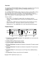
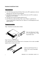
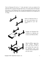
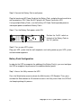
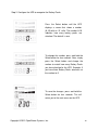
User’s Manual
BPE48V75ART2U
Battery Pack
K01-0000127-02
Table of Contents
OVERVIEW
2
PRODUCT FEATURES
2
TECHNICAL SPECIFICATIONS
3
INSTALLATION INSTRUCTIONS
4
Package Contents
4
HARDWARE INSTALLATION GUIDE
5
Safety Precautions
5
Rackmount Installation
5
Vertical/Standing Installation
7
ELECTRICAL INSTALLATION GUIDE
8
BATTERY PACK CONFIGURATION
9
TROUBLE SHOOTING
11
NEED ADDITIONAL HELP
11
1
Copyright © 2012 CyberPower Systems, Inc.
Overview
The CyberPower BPE48V75ART2U Battery Pack provides extended runtime (XL) for the
PR1000ELCDRTXL2U, PR1500ELCDRTXL2U, PR2200ELCDRTXL2U and
PR3000ELCDRT2U.
The 2U BPE48V75ART2U Battery Pack matches the esthetics of these UPSs, and can
be used in either rack or tower installations. The heavy gauge power cord has a
plug-n-play DC connector for easy installation. The all metal enclosure safely houses
eight 12V 9Ah batteries (The specified type of battery: HR9-12 FR (BB)).
Features include:
• Form Factor – 2U configuration supports both rack and tower mounting
• Scalable – Up to four battery packs can be daisy-chained together for increased
runtimes.
• Metal Housing – Rigid metal construction provides greater durability and safety.
• Power On/Off Switch - Local power switch for manual reset and control.
• Back-panel fuse - User replaceable fuse is easily accessed from the rear panel.
Product Features
5
OUTPUT:
Push To
RESET
INPUT:
48V
48V
BATTERY
PACK
ON
6
OFF
AC OUTPUT
AC INPUT
(Change Only)
7
3
2
1
4
1. On-board user-replaceable fuse cover- User replaceable fuse is easily accessed
from the rear panel.
2. Additional Battery Pack connector sockets
3. Connector plug for additional Battery Packs
4. DC Circuit Protection- Resettable circuit breaker that provides DC output overload
protection.
5. AC Circuit Protection- Resettable circuit breaker that provides AC input overload
protection.
6. AC Output Outlet- This outlet connects to the AC Input Inlet of additional battery
packs.
7. AC Input Inlet- AC power connectivity to wall receptacle.
Copyright © 2012 CyberPower Systems, Inc.
2
Technical Specifications
General
Model
Input
Nominal Input Voltage
Overload Protection
Batteries
Specifications
Sealed Maintenance Free
User Replaceable
Battery Life
Compatibility
UPS Compatibility
Scalability
Battery Packs
Charging
Built-in Charger
Physical
Dimensions (cm)
Weight (kg)
Environmental
Temperature – Operating
Humidity – Operating
Safety Approvals
Certifications
RoHS
3
BPE48V75ART2U
48 VDC, 230VAC
AC, DC circuit protection
(8 of batteries) 12V/ 9.0AH
Yes
Yes
3-5 Years
PR1000/1500/2200ELCDRTXL2U,
PR3000ELCDRT2U
Unlimited (Up to 5 for PR3000ELCDRT2U)
Yes
2U Rack, 43.3 x 8.8 x 48
35
32°F – 104°F
0% to 95% Non-condensing
CE
RoHS Compliant
Copyright © 2012 CyberPower Systems, Inc.
Installation Instructions
Package Contents
Rack-mount Ear Screws (14)
Battery Pack Unit
把把 個
Rack-mount Handles (2)
Rack-mount Ears (2)
Rackmount Rails (1 set – Left and
Base Stand Extensions (2)
Right sides)
Rack-mount Handle Screws (5)
Rackmount Rail Screws (6)
Screw Hole Dust Covers (5)
Screw Hole Dust Cover Screws (5)
User’s Manual
Auxiliary AC Power Cord
Copyright © 2012 CyberPower Systems, Inc.
4
Hardware Installation Guide
Safety Precautions
CAUTION! Before connecting the Battery Pack(s) to the UPS, completely turn off and
unplug the main UPS from the wall receptacle.
CAUTION! Do not disconnect the any Battery Packs when the UPS is turned on or
plugged into a wall receptacle.
CAUTION! Do not connect the battery pack into itself.
CAUTION! Do not add more Battery Packs to the UPS than is specified in the
Technical Specifications section of the User’s Manual. This will damage the unit and
void the warranty.
Rackmount Installation
Step 1: Rackmount ear and handle installation
Attach the Rackmount Handles
to the Rackmount Ears using
the provided screws.
Step 2: Rackmount Rail Installation
Each Rackmount Rail (Left and Right) consists of two pieces that must be assembled
together before installing into the rack.
Attach the two Rackmount Ears to
Battery Pack using the provided
screws.
5
Copyright © 2012 CyberPower Systems, Inc.
Take the Rackmount Rail with an “L” (Left) and attach it to the rear bracket of the
Rackmount Rail using three Rackmount Rail Screws. Do not fully tighten the Rackmount
Rail screws, as the Rackmount Rails will need to be adjusted to fit your rack. Once
complete, perform the same steps for assembling the Rackmount Rail inscribed with an
“R” (Right).
Attach the Rackmount Rails to
your rack using fasteners that
are designed for your rack
system.
Complete the Rackmount Rail
installation by tightening the
screws on the Rackmount Rails.
Slide the UPS on top of the
newly
installed
Rackmount
Rails, and secure the UPS to
your existing rack system [via
the Rackmount Ears] using
fasteners that are designed for
your rack system.
Copyright © 2012 CyberPower Systems, Inc.
6
Vertical/Standing Installation
Step 1: Expand Base Stands
Remove the UPS from the Base Stands, and separate the Base Stands to make room
for the Base Stand Expanders.
Take the Base Stand Expanders and insert them in-between the separated Base Stands.
Be sure the pieces firmly snap together.
Step 2: Install Battery Pack
Insert Dust Covers into the
Rackmount Ear screw holes that
are not being used.
The UPS and Battery Pack
should now fit easily in the
newly expanded Base Stands.
7
Copyright © 2012 CyberPower Systems, Inc.
Electrical Installation Guide
CAUTION! Before connecting the Battery Pack(s) to the UPS, completely turn off and
unplug the main UPS from the wall receptacle.
CAUTION! Do not disconnect the any Battery Packs when the UPS is turned on or
plugged into a wall receptacle.
CAUTION! Do not connect the battery pack into itself.
CAUTION! Do not add more Battery Packs to the UPS than is specified in the
Technical Specifications section of the User’s Manual. This will result in overloading
the unit and will void the warranty.
Step 1: Turn off your existing UPS system
Safely power-down your UPS system and unplug it from the wall receptacle.
Step 2: Connect the Battery Pack to the UPS
Plug the Battery Pack into the
UPS. Ensure the color coded
Battery Pack connector lines up
correctly with the colors in the
UPS socket.
If connecting multiple Battery
Packs, simply use the available
socket(s) on the Battery Packs to
add additional packs.
CAUTION: Do not add more
Battery Packs to the UPS than is
specified
in
the
Technical
Specifications section of the User’s
Manual.
Copyright © 2012 CyberPower Systems, Inc.
8
Step 3: Connect the Battery Pack to wall power
Plug the female end AC Power Cord into the Battery Pack, and plug the male end into a
wall receptacle or PDU. Note: Do NOT plug this AC Power Cord into a UPS.
If using multiple Battery Packs, use the Auxiliary AC Power Cord to provide power to
subsequent power to additional Battery Packs.
Step 4: Turn the Battery Pack power switch ON
Push To
RESET
OUTPUT:
48V
Position the On/Off switch on
the back of the Battery Pack to
INPUT:
48V
BATTERY
PACK
ON
OFF
AC OUTPUT
the “On” position.
AC INPUT
(Change Only)
Step 5: Turn on your UPS system
Plug your UPS system into the wall receptacle, and safely power-up your UPS system
and connected equipment.
Battery Pack Configuration
In order for the UPS to recognize the addition of the Battery Pack(s), you must configure
the UPS to recognize the presence of the additional battery packs.
Step 1: Access the Utility menu on the UPS.
Press the Select button once to activate the Multi-function LCD Readout. Then, press
and hold the Select button for 10 seconds to access the Utility menu. Note: the UPS will
start beeping during this process.
9
Copyright © 2012 CyberPower Systems, Inc.
Step 2: Configure the UPS to recognize the Battery Packs
Press the Select button until the UPS
displays a screen that shows a number
(0-10) with an “A” suffix. The number 0-10
indicates how many battery packs are
attached. The default is zero.
To change this number, press and hold the
Select button for four seconds. Now, simply
press the Select button and change the
number to match how many Battery Packs
you have attached to the UPS. Example: If
you have three Battery Packs attached, set
the number to 3.
To save the changes, press and hold the
Select button for four seconds. This will
return you to the main menu on the UPS.
Copyright © 2012 CyberPower Systems, Inc.
10
Trouble Shooting
Problem
Possible Cause
The UPS LCD does
not perform
expected runtime.
Do not set the UPS
to recognize the
battery pack(s).
Batteries are not
fully charged.
The battery pack
does not work.
Solution
By pressing the display toggle to
select functions. Then, set up the
correct battery pack numbers. The
default setting is 0.
Allow the battery pack to charge for
24 hours. Do not expect full runtime
during this initial charge period.
Specified battery pack models can
use AC to shorten charge time.
The status of circuit
breaker is off.
Switch on the circuit breaker.
The fuse blew.
Contact CyberPower Systems.
Open the cover on the rear panel
and replace the new fuse.
Need Additional Help?
Feel free to contact our Tech Support department with installation, troubleshooting, or
general product questions at [email protected].
CyberPower Systems Inc.
www.cpsww.eu
Entire contents copyright ©2012 CyberPower Systems Inc., All rights reserved.
Reproduction in whole or in part without permission is prohibited.
11
Copyright © 2012 CyberPower Systems, Inc.