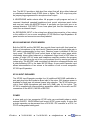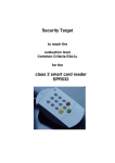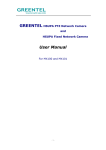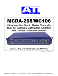
1
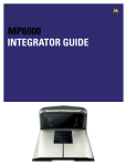
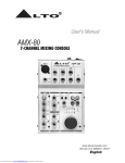
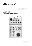
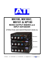
MX100, MX100C,
MX101 & XP100
MONO OUTPUT MIXERS and
INPUT EXPANDER
OPERATING AND MAINTENANCE MANUAL
Model MX101
Model MX100
Model XP100
© Copyright 2011, ATI Audio Inc.
ATI Audio Inc.
■ Tel: 856-626-3480
■
Fax: 856-504-0220
■ [email protected]
■
www.
audio.com
PURPOSE
The MX101 is a three-input miniature mono mixer designed for demanding inthe-field use in broadcast ENG (Electronic News Gathering) and Field Production
applications. The MX101 incorporates most of the features requested by news
professionals, sports announcers, and film and video sound engineers into a tiny
and rugged package.
The MX100 and MX100C Studio Mixers are lower cost, high quality studio mixers
intended for applications which do not require the full feature complement of the
MX101 field mixer. The MX100C adds an output limiter to the basic MX100 features.
The companion XP100 Input Expander provides an additional four switchable
microphone/line inputs and can be used with any of the mixers.
The MX101, MX100 and MX100C Mixers may be used alone or in combination
with the XP100 Expander for any application requiring a compact, rugged and
professional sounding, mixing or input selection system. Several XP100 Expanders may be added for up to a 23-input system with minimal noise buildup in the
mixing network. The MX100 or MX100C alone makes an efficient stereo-to-mono
combiner, a simple voice-over PA driver with inputs for noise masking and background music, or simply a very clean and quiet mike or line input mixer.
Several power modules for field use are available including both replaceable and
rechargeable 24V battery packs, DC/DC converters for 6 to18V automotive or
belt pack battery power and plug-in 24VDC wall supplies. An optional rugged
Field Pack carry bag includes side protection plates for the mixer with quickchange slide mounts for the battery packs.
DESCRIPTION
MX101 MONO FIELD MIXER
Three XLR INPUTS with phantom power and front panel MIC/LINE switches
drive low noise instrumentation preamplifiers. A wide range of internal DIP switch
selectable preamp gains from 60 to 0dB is provided to accommodate either high
or low output microphones and line inputs. Phantom power can be individually
DIP switch selected for each input and is automatically switched off in the Line
Input mode. Front panel switches activate individual LO-CUT FILTERS to reduce
bumps, thumps, wind noise and bass build-up.
A switched TEST TONE oscillator and a SLATE microphone easily mark takes.
An intense LED bargraph VU meter monitors the line output and is easily viewed
even in bright sunlight. A LIMIT indicator and switch shows peaks and limiter ac-
ATI Audio Inc.
■ Tel: 856-626-3480
■
Fax: 856-504-0220
■ [email protected]
■
www.
audio.com
tion. The MX101 provides a high-level line output that will drive either balanced
or unbalanced external loads of 600 ohms or higher. The XLR output may also
be jumper-plug programmed for microphone level output.
A HEADPHONE switch selects either full program or split program and cue. A
recessed, thumbnail operated headphone level control minimizes panel clutter
and once set, tracks the MASTER output. A pre-fader cue from input one or an
external director’s CUE INPUT from a rear panel jack feed the headphone cue
circuit thru an internal trimpot.
An EXPANSION INPUT to the mixing buss allows interconnection of two mixers
or the addition of one or more companion XP100 Mic/Line Input Expanders. All
panel controls and connectors are clearly labeled.
MX100 AND MX100C STUDIO MIXERS
Both the MX100 and the MX100C also provide three inputs with front panel selection of microphone or line input levels. Phantom power and input stage gain is
DIP switch programmable for any input. Phantom power is disabled in the line
input mode. The MASTER level control feeds a high level output stage which
comfortably drives either balanced or unbalanced output loads of 600 ohms or
greater. A bright LED VU meter and headphone amplifier monitors the program
output. The output may be set to line or microphone level by moving an internal
jumper plug. The MX100C adds a switched low distortion compressor/limiter and
a peak-indicating LED to the basic MX100 Mixer. A rear panel Expander input
allows interconnection of two mixers or the addition of one or more companion
XP100 Input Expanders.
XP100 INPUT EXPANDER
The XP100 Input Expander provides four (4) additional MIC/LINE switchable inputs and plugs into the Expansion Buss input of the mixer. 24V phantom power is
available for each input via internal jumper plug selection. The XP100 inputs provide a fixed 40dB microphone gain and unity (0dB) gain for line inputs. The
XP100 is supplied with interconnecting expansion cables for the audio and DC
connections to the MX101, MX100 or MX100C.
POWER
A mixer and up to two companion XP100 units can comfortably share a single
external WA100-1 24VDC/400mA wall mount AC/DC power supply. A mixer and
a single expander can be powered from a DCA100-1 DC converter or a PPA-1 or
PPA-2 rechargeable battery pack.
ATI Audio Inc.
■ Tel: 856-626-3480
■
Fax: 856-504-0220
■ [email protected]
■
www.
audio.com
MOUNTING
Up to three Mixers and/or Input Expanders will mount side-by-side in only one
rack unit high using the available rack mounting shelf. They may also be neatly
stacked or mounted side-by side on your desk with the available angled desk
mounting kits and/or Horizontal Joiner. Extra knob caps are provided to allow you
to color code the input controls. Yellow, red and green caps are supplied in addition to the gray and blue caps on the units. To replace the caps, gently pry out
the old cap and press in the new one.
CIRCUIT DESCRIPTION
INPUT STAGES
The inputs of the MX101, MX100 and MX100C are identical. They are designed
around a very low noise and low distortion, balanced and floating input instrumentation amplifier. The SSM2017 is one of the latest generations of devices designed specifically for use as a low noise microphone amplifier. In addition to ultra low noise and distortion, it features a very high slew rate of 17V/µs virtually
eliminating slew induced Transient Intermodulation Distortion.
The three preamp input stages can be individually set for gains of 20, 40 or 60dB
for microphone inputs and 0 or 10dB for line inputs using the internal rocker DIP
switches S11, S21 and S31, position 2 (ON for 60dB gain) and position 3 (ON for
40dB) (turn both positions OFF for 20dB gain) for microphone inputs and position
4 (ON for 10dB gain, OFF for 0dB) for line inputs. The preamps will have an input
clipping level of +18dBu minus the selected gain; e.g., -42dBu input clipping at
60dB gain (8.5mV peak), -22dBu at 40dB (85mV peak) and -2dBu at 20dB gain
(.85V peak). The gain should be set such that the maximum microphone output
level is always below the input clipping level. Some shotgun type microphones
are designed for very high sensitivity to give them the necessary reach and can
easily overload a high gain input when used in a close talking application. Set the
preamp mic gain to the lowest usable level to avoid overload or select a microphone with a built-in, switchable attenuator which you can switch in for close talking use.
The XP100 has a fixed input gain of 40dB for microphone inputs and 0dB (unity
gain) for line inputs. The XP100 is best used with normal studio type microphones with peak outputs below -22dBu (85mV peak).
The MX101 incorporates switchable single pole low-cut 125 Hz filters on each
input to help block wind noise.
ATI Audio Inc.
■ Tel: 856-626-3480
■
Fax: 856-504-0220
■ [email protected]
■
www.
audio.com
PHANTOM POWER
Phantom power at regulated +20.2VDC through an equivalent 1.66Kohm resistance is supplied to a microphone when the appropriate rocker DIP switch (S11,
S21, S31 position 1) is selected ON and the MIC/LINE pushbutton is in the MIC
position. This voltage level is more than adequate for most, but not all, phantom
powered microphones even though they may be labeled 48V phantom power.
Check the microphone specification sheet for 9 to 52V or 12 to 48V ratings (includes almost all electret type condenser microphones). Those few RF condenser microphones requiring a full 48VDC for phantom power will need our optional
PH48-1 internal accessory board.
On the XP100 only, 24VDC phantom power is individually selected for each input
with a jumper plug, P1, P2, P3 or P4. Moving the jumper plug closest to the P1,
P2, P3 or P4 marking selects phantom power for the corresponding XP100 input.
Of course, dynamic microphones don’t care if there is phantom power or how
much there is of it or whether it’s even turned on or not so long as they are properly wired with their coil across pins 2 and 3 of the XLR connector (shield to Pin
1). If they are not wired correctly they may sound real funny with the phantom
power turned on (or not at all, maybe ever again).
LEVEL CONTROLS
Each of the three inputs is controlled by its own audio taper potentiometer. These
controls preferably operate in the twelve-to-four o'clock range. If you consistently
run the input fader below the ten o’clock position, you should probably reduce the
preamp gain setting one step with the internal DIP switches to assure maximum
headroom and control resolution. If you have a preferred position for a particular
input, you can pop out the knob cap and reposition its reference indicator line to
the twelve o'clock position. A selection of colored knob caps is included with the
unit to allow you to color code the inputs.
The Master Control adjusts the Line Output as indicated by the LED meter. The
Master gains and output stages add 32 dB of additional gain. The Master Control
should normally operate above the two o'clock position to maximize internal
headroom and optimize noise performance.
LINE OUTPUT
The output stage of the mixer, A5, utilizes a unique active balanced output driver
IC, the SSM2142, that can sense whether the connected load is balanced and
floating or is unbalanced due to either side being grounded. A balanced output
ATI Audio Inc.
■ Tel: 856-626-3480
■
Fax: 856-504-0220
■ [email protected]
■
www.
audio.com
load will be driven with equal and anti-phase levels on the HI and LO output
lines. An unbalanced (one side grounded) load will cause the driver IC to shut off
the signal output to the grounded side of the load and double the output level applied to the other side, thus maintaining equal output to either type of load. The
output stage will drive loads of 600 ohms and higher. Nominal output is +4dBm
with clipping at +22dBm into balanced loads. Maximum output at clipping is reduced by 6dB when driving an unbalanced load, since the full output swing of only one driver is available. A jumper plug, P1, located just behind the output XLR
connector selects either +4dBm line level or -50dBm microphone level output.
HEADPHONES
A front panel 1/4” TRS (stereo) jack and thumbnail-adjust gain control provides a
monaural, in-phase signal to both sides of a set of stereo headphones. Only stereo headphones should normally be used with the MX100; however, mono
phones can be used in a pinch at reduced levels. The headphone output provides 100mW to phones of up to 600 ohm impedance and reduced levels into
higher impedance phones. On the MX101, a panel switch can select a split listening mode which allows a pre-fade listen feed to one ear either from Mixer Input 1 or from an external director’s cue fed thru a rear 2.5mm Tip-Sleeve jack.
Inserting a plug into the rear cue jack interrupts the feed from Mixer Input 1. The
cue headphone level is adjusted with an internal trimpot, R84, and is not affected
by the front panel headphone level adjustment.
LED METERING
A ten segment, three color LED bargraph display meters the output with a VU
average response characteristic. Internal meter calibration pot R70 sets the 0VU
meter reference to +4dBm output level and is adjustable to read 0VU for outputs
from -10 to +8dBm.
COMPRESSOR/ LIMITER
The MX101 and the MX100C incorporate a low distortion optical compressor with
a front panel switch and peak indicating LED. The compressor threshold adjustment, R76, is factory set for a sine wave threshold at +3VU meter indication. The
threshold setting is independent of the actual mixer output level.
SLATE MICROPHONE AND TEST TONE OSCILLATOR
The MX101 includes a sensitive slate microphone built into the front panel with a
momentary switch to activate it. The compact nature of the MX101 precluded a
ATI Audio Inc.
■ Tel: 856-626-3480
■
Fax: 856-504-0220
■ [email protected]
■
www.
audio.com
slate mike level adjustment.
A 740Hz low distortion test tone oscillator is selected by the maintained up position of the same panel switch. The oscillator is injected into the mixing buss at
the optimum level to set your master control for 0VU (+4dBm out). A bi-color LED
lights to tell you that funny sound in the mix is the test tone oscillator you forgot to
turn off.
EXPANSION INPUT
Loop-thru 1/8" T-S (Tip-Sleeve) jacks J7 and J8, mounted on the rear panel, feed
the mixing buss at the input of A4A. This point floats at half the supply voltage
and must not be externally grounded. This point is low impedance, current summing node on which you should measure nothing other than a DC voltage.
EXPANSION OUTPUT
The XP100 amplified mixing buss output appears on paralleled 1/8" Tip-Sleeve
jacks J7 and J8. The nominal output is +4dBu through a 200K-ohm source resistance, which feeds the current summing expansion input of the MX100 when so
connected. The paralleled output jacks, J7 and J8, allow multiple XP100 units to
be looped together and into the mixer.
POWER
Required: 22 to 30VDC from an external power source. The DC power connector
is wired with the center pin negative and the outer cylinder positive. A series diode and a thermal overload device protect the unit from reversed polarity DC input. The mixers and expander incorporate an "artificial ground" power supply
splitting circuit to continuously track the DC input voltage and provide a center
point voltage reference for the audio stages.
A low dropout regulator in the MX100 and MX101 provides a regulated 20.2VDC
for phantom powering microphones from inputs as low as 21VDC. Active regulation of the phantom power supply helps eliminate any possibility of oscillation due
to unbalanced loading of the phantom supply by the microphone.
All mixers share a common external 24VDC "Wall Wart" type power supply for
fixed installations. A pair of loop-thru DC connectors on the rear of each Mixer
and Input Expander permits several units to be daisy-chained with P/N 20602-1
DC power cables to a single WA100-1 power supply (provided with all MX units).
Each XP100 Expander is supplied with a set of loop-thru DC and audio cables for
easy interconnection to a companion MX100. The WA100-1 is a 400mA supply.
ATI Audio Inc.
■ Tel: 856-626-3480
■
Fax: 856-504-0220
■ [email protected]
■
www.
audio.com
Each MX100 draws about 120mA and each XP100 draws 70mA; therefore, one
MX100 could be combined with up to four XP100 units on a single power supply
module (120 + (4 X 70) = 400mA). Any combination which totals less than
400mA can be powered by a single WA100-1 supply.
BATTERY POWER
Several battery power systems are available for field powering of the MX100 or
MX101.
The BBU100-1 houses four 9V alkaline or lithium batteries and will power the
MX101 for four to six hours.
The PPA-1 rechargeable gel-cell pack powers an MX101 for approximately six
hours and can be recharged overnight with the included dual-mode charger. The
PPA-1 is capable of approximately 500 charge-discharge cycles.
The DCA100-1 DC-to-DC Converter accepts inputs from 6 to 18 VDC and outputs 24VDC to operate a mixer from a 6.0 or 7.2V camcorder Ni-Cad, belt-pack
Ni-Cad packs, automotive 12V or 12.0-to-14.4 V NP-1 batteries. The DCA100-1
requires a standard 4 pin XLR input connector from the battery source (Pin 4
Positive, Pin 1 Ground). Adapter fixtures are available for NP-1 type batteries,
which can power an MX101 thru a DCA100-1 for up to 12 hours (13.2V NiMH
type).
The BBU100-1, PPA-1 and DCA100-1 can all mount directly to the underside of
the case or slip into the quick-change slide mounts provided with the PROK-1
protection kit or the ABAG-1 carry case. An NP-1 type battery and a spare can
be Velcro mounted to the inside of the carry case.
INSTALLATION
UNPACKING
Inspect the equipment. Shake it to see if anything is rattling around inside. If
there is any visible damage to the unit or to the box it came in, contact the factory
but do not return anything to ATI without prior authorization and shipping instructions. It may be necessary to have the shipping company inspect the unit and the
box at your location. Count the pieces! Don't throw out the boxes and packing
material until you are sure you have everything that is coming to you. The XP100
comes with an audio cable, P/N 20612-1, a DC cable, P/N 20602-1, and this instruction book. The MX100 comes with this instruction book but does not come
with any cables. The MX100 needs either its own included WA100-1 power
supply or an optional DC cable, P/N 20602-1, to share the supply of another mix-
ATI Audio Inc.
■ Tel: 856-626-3480
■
Fax: 856-504-0220
■ [email protected]
■
www.
audio.com
er. Make sure you have unpacked any battery packs or converters you have ordered. Rack and desk mounting hardware may be packed in with the unit even
though ordered separately. Wall mount power supplies may either be included in
with the unit or shipped in their own box. The PROK-1 and ABAG-1 are generally
pre-assembled to the mixer if shipped direct from the factory; otherwise, they will
be in a separate box.
SETUP ADJUSTMENTS
The following adjustments require that the mixer cover be removed and should
be made before rack mounting or first use of the mixer. Remove the top cover by
removing four Philips head screws (the top two on each side).
PHANTOM POWER
With a small pointy object select phantom microphone power if required by pushing ON the rocker type DIP switch S11 position 1 for input one (left hand switch,
front rocker, push left) Repeat for S21 and S31 for inputs two and three.
MICROPHONE INPUT GAIN
Set the desired input stage gain for your microphones by setting rocker 2 ON to
select 60dB input gain for low output mics, turn rocker 3 ON for 40dB gain for
typical microphones or turn rockers 2 and 3 both OFF for 20dB gain and maximum input headroom for high output microphones.
LINE INPUT GAIN
Gains of 0 or 10dB may be set for line inputs by turning rocker 4 OFF or ON, respectively. This setting is effective only when the front pushbutton is set for LINE
input.
OUTPUT LEVEL
If you require a microphone level output from the mixer, move the jumper plug
P1, located on the PC board just behind the output XLR connector. This inserts a
balanced 54dB attenuator pad into the output line. To set the 0VU meter indication to an output level other than the factory setting of +4dBm, adjust trimpot R70.
ATI Audio Inc.
■ Tel: 856-626-3480
■
Fax: 856-504-0220
■ [email protected]
■
www.
audio.com
CUE/ MONITOR HEADPHONE LEVEL
The CUE/MONITOR level adjust trimmer on the MX101 (R74) is factory set for a
comfortable listening level at a director’s cue input level of -10dBu (.25Vrms) but
can be adjusted as required.
MOUNTING
You may rack mount one, two, or three units across in a standard EIA 19" rack
requiring only 1-3/4" of vertical space. Rack Mount Shelf Assembly P/N 21075501 mounts one, two or three units. Use 1/3 RU Filler Panels, P/N 21097-501, to
fill any unused space on the 21075-501 Rack Shelf.
Single desk mounting kits consist of a pair of angled base plates that mount under the lower front and rear cover screws of a single unit to raise and to tilt it for
easy use. In addition, one or more sets of vertical stacking plates, mounting to
the upper front and rear cover screws of the bottom unit, allow multiple units to
be stacked. Several units can be desk mounted side by side and even stacked
side-by-side using horizontal joiner kits together with mounting base and stacker
kits. P/N 20617-501 is the angled base kit. P/N 20617-502 is the base plus one
stacker kit (two high). P/N 20617-503 is the base plus two stackers (three high).
P/N 20617- 504 is the stacker kit by itself and P/N 20617-505 is a horizontal joiner kit.
Detailed instructions for mounting the protection plates and battery pack slides
are included with the PROK-1 and ABAG-1 if they have not been pre-assembled
to the mixer.
AUDIO CONNECTIONS
XLR type inputs and outputs are wired with pin 2 as HI and pin 3 as LOW. Pin 1
of all input connectors is grounded and is the cable shield and DC return connection for phantom microphone power. Pin 1 of the output connector is grounded.
Active balanced outputs require a reference ground connection to the receiving
device for proper operation. This ground can be provided by the rack frame or a
studio buss connection but is preferably carried through by the output cable
shield.
POWER CONNECTIONS
Hum and noise performance of the XP100 can be degraded by poor DC ground
connections between it and the MX100. Use of the recommended rack and desk
mounting kits will assure a good ground connection between units by firmly
ATI Audio Inc.
■ Tel: 856-626-3480
■
Fax: 856-504-0220
■ [email protected]
■
www.
audio.com
strapping their chassis together. CAUTION! The outer shell of the DC interconnect cables is positive relative to the chassis. Do not allow a DC cable plugged
into a powered unit to hang loose where it might short against the chassis or rack
frame.
MAINTENANCE
There is no routine maintenance required. If you have a problem, check the panel LED indicators to assure that the units have DC power, eliminate by substitution microphones, input and output cables, connectors, downstream devices,
Mixer-to-Expander interconnect cables and power supplies. If all else fails, read
your warranty (even though it probably ran out yesterday) and call us for sympathy and overpriced parts.
POWER SUPPLY LEVELS
The recommended loaded DC input voltage range is 22 to 30VDC over the full
range of AC line voltage tolerances. The audio circuits continue to work with reduced headroom below 22VDC but the LED VU meter will not indicate the top
segments. Momentary surges up to 36VDC will cause some increased internal
heating, but above 36VDC call our parts department for some of those expensive
ICs.
OPERATING POINTS
An internal reference voltage equal to 1/2 the supply voltage is generated by A9
in the MX100 and A5B in the XP100. All audio stage inputs and outputs should
show a DC level equal to this voltage when measured with a high impedance
meter. XLR audio inputs and outputs are capacitor coupled and ground referenced. The expansion buss input is at this DC reference level and must not be
accidentally grounded by dangling audio interconnects cables.
METER CALIBRATION
To set, adjust the Master Gain Control for the desired 0VU output level in the
range of +8 to -10dBm (+4dBm nominal) with an independent audio voltmeter.
Adjust the internal meter calibration trimpot, R70, for 0VU indication on the bargraph meter.
ATI Audio Inc.
■ Tel: 856-626-3480
■
Fax: 856-504-0220
■ [email protected]
■
www.
audio.com
SWITCH MAINTENCE
The front panel MIC/LINE switches have good wiping contacts and should need
little attention. The switches are sealed and impossible to clean. In addition, most
spray solvents will wash out the internal lubricant and cause premature mechanical failure. A good fix, if the switches get noisy, is to sit down at the unit, think
about your girl friend for a while (or Britney Spears or Madonna, depending on
your age bracket) and push those little red buttons about 500 times each. If that
doesn't cure the problem, call us for more sympathy and a high-priced replacement.
POTENTIOMETERS
Input and Master Gain controls are 10Kohm audio taper potentiometers. Replacements are our P/N 10034-2. The headphone pot is a 1M-ohm linear taper
pot, our P/N 10058-1.
ATI Audio Inc.
■ Tel: 856-626-3480
■
Fax: 856-504-0220
■ [email protected]
■
www.
audio.com
PERFORMANCE SPECIFICATIONS
OUTPUT LEVEL:
+22dBm MAX, +4dBm Nominal into 600 ohm
balanced or unbalanced lines. Output is selectable +4dBm (Line) or -50dBm (Mic).
FREQUENCY RESPONSE:
+0/-.5dB 20Hz to 20kHz
FILTERS (MX101 only):
Switchable low cut filters -15dB @ 20 Hz, -3dB
@ 125 Hz
DISTORTION:
.5% THD Maximum 20Hz to 20kHz at +20dBm
NOISE:
MIC Input: EIN = -124dBm, 54dB gain
LINE Input: EIN = -88dBm, 14dB gain, 20Hz to
20kHz measurement bandwidth
GAIN, MX SERIES:
MIC: 52, 72 & 92dB; LINE: 32 & 42Db
Gain of each input is selectable
GAIN, XP100:
MIC: 40dB; LINE: 0dB
HEADPHONE OUTPUT:
100mW to 600/150-Ohm Headphones, ¼-inch
TRS (Stereo) Jack
LIMITER:
MX101/MX100C only: 5:1 SLOPE, Attack
Time 50ms, Recovery Time 300ms for 10dB
change
PHANTOM POWER:
+20VDC regulated @ 4ma through paralleled
3.32K Ohm resistors
POWER:
24VDC, 22 to 30 VDC max. MX100 and
MX101 draw 120 mA nominal, 150 mA max.
XP100 draws 70 mA nominal, 82 mA max.
DIMENSIONS in. (cm):
1.75(4.45)H X 5.6(14.22)W X 5.75(14.6)D
WEIGHT
1.25 lbs. (.57kg) Net; 3 lbs (1.4kg) Shipping
MOUNTING:
Free standing or rack mountable; one, two or
three units in 1-3/4 vertical rack space
CONNECTORS:
3 Standard 3-pin XLR female inputs and 1 XLR
male output; Pin 1 ground
ATI Audio Inc.
■ Tel: 856-626-3480
■
Fax: 856-504-0220
■ [email protected]
■
www.
audio.com
CUE (Director Input):
MX101 only: Unbalanced -10dBu, 2.5 mm T-S
jack.
POWER SUPPLIES:
WA100-1
Wall mount power supply (UL), 24VDC @
.4amp, 115 VAC/60 Hz, included as standard
WA100-2
Wall mount power supply for international use,
90-264VAC input via interchangeable connectors, 24VDC @ .4 amp output (optional)
Rack Mount Kits:
21075-501
21097-501
Mounts up to 3 units
1/3 RU Filler Panel
Desk Mount Kits:
20617-501
20617-502
Angled Desk Mount Base
Angled Desk Mount Base and
One Stacker (2 units high)
Angled Desk Mount Base and
Two Stackers (3 units high)
Stacker (2 units high)
Horizontal Joiner (2 units side-by
side)
20617-503
20617-504
20617-505
FIELD ACCESSORIES:
PROK-1
Unit protection kit containing a set of side
plates with attached side brackets. The side
plates protect the front panel controls and the
rear XLR connectors from impact damage and
provide attachment points for a shoulder strap
(not included); the slide brackets allow easy
quick change of remote power packs.
ABAG-1
Wraparound carry case with strap (PROK-1
above is included), houses the MX series of
mixers with slide mounted PPA, DCA or BBU
power modules; space for auxiliary NP-1 type
batteries
REMOTE POWER PACKS (for use with Field Accessories):
PPA-1
ATI Audio Inc.
Integrated power pack assembly for remote
operation, mounts to a mixer; includes housing
with rechargeable 24VDC gel-cell battery pack
(four to six hours operation), and an external
■ Tel: 856-626-3480
■
Fax: 856-504-0220
■ [email protected]
■
www.
audio.com
battery charger operating at 115VAC/60 Hz
PPA-2
Same as above except battery charger operating at 230VAC/50 Hz; Euro-plug; Contact factory for other plug configurations
PPA-B
Extra 24VDC rechargeable gel-cell battery
pack, charger not included
DCA100-1
Integrated DC/DC converter, mounts to the
mixer and accepts external battery power with
DC inputs from 6 to 18 volts to produce 24VDC
mixer power; four-pin XLR battery connector
BBU100-1
Battery Pack, houses four 9V alkaline or lithium
batteries (not included) for remote operation or
back-up power
ATI Audio Inc.
■ Tel: 856-626-3480
■
Fax: 856-504-0220
■ [email protected]
■
www.
audio.com
One Year Limited Warranty
ATI warrants this product to be free from defects in materials and workmanship to its original
owner for a period of one year from date of purchase. ATI will repair or replace such product or
part thereof, which upon inspection by ATI, is found to be defective in materials or workmanship.
The Proper Return Authorization Number must be obtained from ATI in advance of return. Contact ATI at 856-626-3480 or email [email protected] to receive the number and instructions for
return of your unit.
A written statement providing the name, address, daytime telephone number and email address
of the original owner, together with receipt from the original purchase, and a brief description of
any claimed defects, must accompany all returns. Parts or product for which replacement is made
shall become the property of ATI.
The customer shall be responsible for costs of transportation and insurance to the factory of ATI,
and shall be required to prepay such costs.
ATI shall use reasonable efforts to repair or replace any product covered by this limited warranty
within thirty days of receipt. In the event repair or replacement shall require more than thirty days,
ATI shall notify the customer accordingly. ATI reserves the right to replace any product that has
been discontinued from its product line with a new product of comparable value and function.
This warranty shall be void in the event a covered product has been damaged, or failure is
caused by or attributable to acts of God, abuse, accident, misuse, improper or abnormal usage,
failure to follow instructions, improper installation or maintenance, alteration, or lightning, power
fluctuations and other incidental or environmental conditions. Further, product malfunction or deterioration due to normal wear is not covered by this warranty.
ATI DISCLAIMS ANY WARRANTIES, EXPRESS OR IMPLIED, WHETHER OF
MERCHANTABILITY OF FITNESS FOR A PARTICULAR USE, EXCEPT AS EXPRESSLY SET
FORTH HEREIN. THE SOLE OBLIGATION OF ATI UNDER THIS LIMITED WARRANTY SHALL
BE TO REPAIR OR REPLACE THE COVERED PRODUCT, IN ACCORDANCE WITH THE
TERMS SET FORTH HEREIN. ATI EXPRESSLY DISCLAIMS ANY LOST PROFITS, GENERAL,
SPECIAL, INDIRECT OR CONSEQUENTIAL DAMAGES WHICH MAY RESULT FROM
BREACH OF ANY WARRANTY, OR ARISING OUT OF THE USE OR INABILITY TO USE ANY
ATI PRODUCT.
Some states do not allow the exclusion or limitation of incidental or consequential damages or
limitation on how long an implied warranty lasts, so the above limitations and exclusions may not
apply to you.
This warranty gives you specific legal rights, and you may also have other rights that vary from
state to state.
ATI reserves the right to modify or discontinue, without prior notice to you, any model or style
product.
If warranty problems arise, or if you need assistance in using your product contact us.
ATI Audio Inc.
■ Tel: 856-626-3480
■
Fax: 856-504-0220
■ [email protected]
■
www.
audio.com