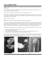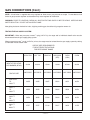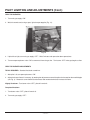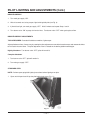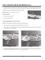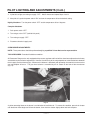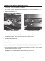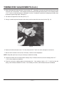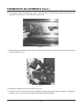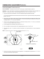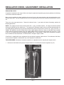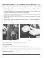
1
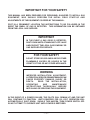
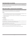
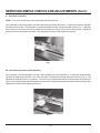
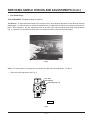
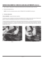
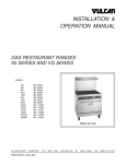
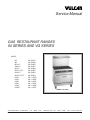
Service Manual
GAS RESTAURANT RANGES
90 SERIES AND VG SERIES
MODEL
24L
48L
481L/LC
148L/LC
36L/LC
60L/LC/LCC
160L/LC
260L/LC/LCC
VG24
VG36
VG48
VG60
VG160
VG260
ML-52947
ML-52949
ML-52950
ML-52951
ML-52948
ML-52952
ML-52953
ML-52954
ML-114553
ML-114554
ML-114957
ML-114555
ML-114556
ML-114557
MODEL 36L/VG36
VULCAN-HART
COMPANY,
FORM 31056 Rev. A (1-99)
P.O.
BOX
696,
LOUISVILLE,
KY
40201-0696,
TEL. (502) 7 7 8 - 2 7 9 1
IMPORTANT
OPERATING, INSTALLING AND SERVICE PERSONNEL
Operating information for this equipment has been prepared for use by qualified and/authorized
operating personnel.
All installation and service on this equipment is to be performed by qualified, certified, licensed and/
authorized installation or service personnel, with the exception of any part marked with a in front of the
part number.
Service may be obtained by contacting the Factory Service Department, Factory Representative or Local
Service Agency.
DEFINITIONS
QUALIFIED AND/OR AUTHORIZED OPERATING PERSONNEL
Qualified or authorized operating personnel are those who have carefully read the information in this
manual and are familiar with the equipments functions or have had previous experience with the
operation of the equipment covered in this manual.
QUALIFIED INSTALLATION PERSONNEL
Qualified installation personnel are individuals, a firm, corporation or company which either in person or
through a representative are engaged in, and are responsible for:
1. The installation of gas piping from the outlet side of the gas meter, or the service regulator when the
meter is not provided, and the connection and installation of the gas appliance. Qualified
installatiopersonnel must be experienced in such work, be familiar with all precautions required, and
have complied with all requirements of state or local authorities having jurisdiction. Reference in the
United States of America - National Fuel Gas Code ANSI Z223.1 (Latest Edition). In Canada Canadian Standard CAN/CGA-B149.1 NAT. GAS (Latest Edition) or CAN/CGA-B149.2 PROPANE
GAS (Latest Edition).
2. The installation of electrical wiring from the electric meter, main control box or service outlet to the
electric appliance. Qualified installation personnel must be experienced in such work, be familiar with
all precautions required, and have complied with all requirements of state or local authorities having
jurisdiction. Reference: In the United States of America - National Electrical Code ANSI/NFPA No.
70 (Latest Edition). In Canada - Canadian Electric Code Part 1 CSA-C22.1 (Latest Edition).
3. The installation of steam piping from the source of supply to the service inlet of the appliance.
Qualified installation personnel must be experienced in such work, be familiar with all precautions
required, and have complied with all requirements of state or local authorities having jurisdiction.
QUALIFIED SERVICE PERSONNEL
Qualified service personnel are those who are familiar with Vulcan equipment who have been endorsed
by the Vulcan-Hart Corporation. All authorized service personnel are required to be equipped with a
complete set of service and parts manuals and stock a minimum amount of parts for Vulcan equipment.
© VULCAN-HART COMPANY, 1998
—2—
IMPORTANT FOR YOUR SAFETY
THIS MANUAL HAS BEEN PREPARED FOR PERSONNEL QUALIFIED TO INSTALL GAS
EQUIPMENT, WHO SHOULD PERFORM THE INITIAL FIELD START-UP AND
ADJUSTMENTS OF THE EQUIPMENT COVERED BY THIS MANUAL.
POST IN A PROMINENT LOCATION THE INSTRUCTIONS TO BE FOLLOWED IN THE
EVENT THE SMELL OF GAS IS DETECTED. THIS INFORMATION CAN BE OBTAINED
FROM THE LOCAL GAS SUPPLIER.
IMPORTANT
IN THE EVENT A GAS ODOR IS DETECTED,
SHUT DOWN UNITS AT MAIN SHUT-OFF VALVE
AND CONTACT THE LOCAL GAS COMPANY OR
GAS SUPPLIER FOR SERVICE.
FOR YOUR SAFETY
DO NOT STORE OR USE GASOLINE OR OTHER
FLAMMABLE VAPORS OR LIQUIDS IN THE
VICINITY OF THIS OR ANY OTHER APPLIANCE.
WARNING
IMPROPER INSTALLATION, ADJUSTMENT,
ALTERATION, SERVICE OR MAINTENANCE CAN
CAUSE PROPERTY DAMAGE, INJURY OR
DEATH.
READ THE INSTALLATION,
OPERATING
AND
MAINTENANCE
INSTRUCTIONS THOROUGHLY BEFORE
INSTALLING OR SERVICING THIS EQUIPMENT.
IN THE EVENT OF A POWER FAILURE, THE PILOTS WILL REMAIN LIT AND THE UNIT
WILL CONTINUE TO FUNCTION. UNITS EQUIPPED FOR 120 VOLT OPERATION WILL
AUTOMATICALLY SHUT DOWN. SHOULD THIS HAPPEN, TURN POWER SWITCH OFF.
DO NOT ATTEMPT TO OPERATE UNIT UNTIL POWER IS RESTORED.
—3—
GAS RESTAURANT RANGE MODELS
GAS RESTAURANT RANGE MODELS
60L, 60LC, 60LCC,
VG60
48L
260L, 260LC, 260LCC,
VG260
148L, 148LC
160L, 160LC,
VG160
481L, 481LC
24L,
VG24
36L, 36LC,
VG36
PL-53007
NOTE: Reference to 90 Series Convection Ovens will include only the following models: 36LC, 148LC, 481LC, 60LC,
60LCC, 160LC, 260LC, or 260LCC.
—4—
SERVICE MANUAL
GAS RESTAURANT RANGES
INDEX
PLEASE KEEP THIS MANUAL FOR FUTURE REFERENCE
DESCRIPTION
PAGE
SERVICE NOTATIONS
6
UNITS MOUNTED ON CASTERS
7
SERVICING SIMPLE CHECKS AND ADJUSTMENTS
7-10
GAS CONNECTIONS
11, 12
TESTING THE GAS SUPPLY SYSTEM
12
ORIFICE SIZE REQUIREMENTS FOR DIFFERENT ELEVATIONS
12
PILOT LIGHTING AND ADJUSTMENTS
13-17
THERMOSTAT ADJUSTMENTS
18-22
REGULATOR CHECK, ADJUSTMENT, INSTALLATION
23-25
STANDARD OVEN & GRIDDLE THERMOSTAT REPLACEMENT
26-28
CONVECTION OVEN THERMOSTAT REPLACEMENT
STANDARD OVEN PILOT SAFETY VALVE CHECK, REPLACEMENT
29
30-32
OVEN PILOT CHECK, REPLACEMENT
33
THERMOCOUPLE CHECK, REPLACEMENT
34
OVEN BURNER NOZZLE AND ORIFICE CHECK, REPLACEMENT
35
OVEN BURNER CHECK, REPLACEMENT
36
TOP SECTION PILOT CHECK, REPLACEMENT
37
PILOT ADJUSTMENT VALVE REPLACEMENT
37
TOP SECTION BURNER VALVE AND NOZZLE CHECK, REPLACEMENT
38
CONVECTION OVEN MOTOR AND DOOR SWITCH CHECK, REPLACEMENT
SOLENOID CHECK
38-45
46
CENTRIFULGAL SWITCH CHECK
47, 48
REMOVAL OF CONVECTION OVEN SOLENOID
48-51
—5—
DEDICATED TECHNICAL SERVICE HOT LINE(1-502-778-2791)
SERVICE NOTATIONS:
1. The procedures outlined in this manual are to be performed only by Vulcan-Hart authorized service representatives.
2. An authorized Vulcan-Hart service representative is one who is familiar with Vulcan equipment and who has been
endorsed by Vulcan-Hart Company to service the equipment. All authorized service personnel are required to stock
a minimum amount of parts and should be equipped with a complete set of wiring diagrams, service and parts manuals
covering all Vulcan-Hart equipment.
3. For all field conversion service installation procedures, refer to the codes and compliances outlined in the installation
and operation manual, F-31055.
4. The unit rating plate stating model no., serial no., unit gas type, and voltage is located on the inside of the lower kick
panel.
5. Caution should be taken when servicing this equipment. Some service testing is required while the unit is in operation.
During these test procedures, it is advisable not to leave the unit unattended and to exercise caution during all testing
operations.
WARNING: THE RANGE AND ITS PARTS ARE HOT. BE VERY CAREFUL WHEN OPERATING OR SERVICING THE
RANGE.
—6—
UNITS MOUNTED ON CASTERS
Units mounted on casters utilizing a flex hose and quick-disconnect must be installed with a restraining device. The
restraining device must be connected at all times. If disconnection of the device is necessary, turn off the gas supply before
disconnection. Reconnect the restraint before turning the gas supply on and returning the unit to its original installation
position and before beginning unit operation.
SERVICING SIMPLE CHECKS AND ADJUSTMENTS
The following is a list of simple checks and adjustments which are commonly associated with the malfunctioning of this
equipment. Perform these checks and adjustments for relevant unit symptoms before the removal of any major parts or
controls. Call the number on the front of this manual for any service related questions.
CHECKS
1. Check the unit rating plate and verify that the gas type, pressure rating and voltage ratings (if applicable) are correct
for the unit and the installation site affected. If not correct, make required adjustments.
2. Ensure that all unit and main gas and electrical supply lines are connected properly. (For electrical problems, check
for tripped circuit breakers.)
ADJUSTMENTS
1. Legs/Casters
TOOLS REQUIRED: Carpenter’s level, channel locks.
If the cooked product seems to be lopsided, check the leveling of the unit. Place a carpenter’s level inside the oven cavity
across the oven rack(s). Level the unit from front to back and from side to side.
To adjust the leveling of the unit, tilt the unit to one side and, using channel locks, unscrew the adjustable leg insert as
required. Repeat this procedure as necessary for each leg.
NOTE: Casters for this range are of the non-leveling type. Therefore, the surface which the unit is resting on must be level.
If floor surface is not level, the unit will experience cooking problems until the range is level.
Check the unit leveling again before leaving the store to ensure that the problem has been corrected.
—7—
SERVICING SIMPLE CHECKS AND ADJUSTMENTS (Cont.)
2. Oven Door Turnbuckle
NOTE: For the 24L and 48L units, refer to procedure outlined under 2A.
If the oven door is not closing properly, the door turnbuckle may require adjustment. To adjust the turnbuckle, flip down
the lower front kick panel. The turnbuckle is connected between the right- and left-hand door springs (Fig. 1). With your
hand, rotate the cast center piece of the turnbuckle two rotations at a time, then check the door tension. Repeat this
procedure until the door works as desired. After adjustment has been made, tighten the locknuts.
Fig. 1
2A. 24L and 48L Oven Door J-Bolt Assembly
If the oven door is not closing properly, the door J-bolt assembly may require adjustment. To adjust the J-bolt assembly,
flip down the lower front kick panel. The J-bolt assembly is connected to the right-hand bell crank arm (Fig. 2). The
adjustment is made by the two 1/4-20 locknuts. Turn each nut in a clockwise direction to increase tension on the door; turn
each nut in a counterclockwise direction to decrease the tension. Repeat this procedure until door works as desired. After
adjustment has been made, tighten the locknuts.
Fig. 2
—8—
SERVICING SIMPLE CHECKS AND ADJUSTMENTS (Cont.)
3. Pilot Flame Height
TOOLS REQUIRED: Standard flat blade screwdriver.
Top Burners: To adjust pilot flame height of the unit top burners, locate the pilot adjustment screws found on the front
manifold pipe. It is not necessary to remove the manifold cover, as adjustment access holes have been provided in the
panel. With screwdriver, turn the adjustment screw of the pilot valve experiencing the pilot flame height problems
(Fig. 3). Rotate the screw clockwise to decrease and counterclockwise to increase the flame height.
Fig. 3
Oven: On rare occasions, the standard or convection oven pilot may need adjustment. To do this:
RO
E RT S
O
Y S
OUT
RA
N
AW
C
Oven Pilot
Control Button
Pilot Adjusting Cap
H
B
IN
1. Remove the pilot adjustment cap (Fig. 4)
PL-50117
Fig. 4
—9—
SERVICING SIMPLE CHECKS AND ADJUSTMENTS (Cont.)
2. With screwdriver, adjust pilot key (located under pilot adjustment cap) to provide the proper size flame.
3. Replace pilot adjustment cap.
NOTE: If unit still is not heating correctly, refer to THERMOSTAT ADJUSTMENTS on Page 18.
4. Air Shutter Adjustment
TOOLS REQUIRED: Standard flat blade screwdriver.
The efficiency of the oven depends on a delicate balance between the air supply and the volume of gas. Whenever this
balance is disturbed, poor operating characteristics and excessive gas consumption will occur.
The gas mixer balance is controlled by an air shutter on the front of the oven burner. A yellow streaming flame on the burner
is an indication of insufficient air. To correct this condition, loosen the screw locking the shutter into position. Rotate the
air shutter open until the burner flame begins to lift from the burner, then close the shutter slightly down again and lock it
into place (Fig’s. 5 & 6).
Fig. 6
Fig. 5
— 10 —
GAS CONNECTIONS
CAUTION: All gas supply connections and any pipe joint compound used must be resistant to the action of
propane gases.
Each unit is factory-equipped with the type gas specified on the rating plate. The installation gas connection is a 3/4" 14
FPT thread ANSI schedule #40 standard pipe.
Codes require that a gas shutoff valve be installed in the gas line ahead of the range.
Standard units are equipped with fixed burner orifices which coincide with the proper unit operation elevation. See Orifice
Size Requirements for Different Elevations on Page 12. NOTE: Do not attempt to drill out orifice sizes. Obtain proper
conversion kit from Vulcan-Hart depot.
Install the gas pressure regulator.
NOTE: Before installing, check regulator supplied against unit rating plate gas supply.
As of 7/11/90, the gas pressure regulator is NOT factory installed to this equipment. The regulator for this unit gas type
is sealed within a plastic bag attached to the oven rack inside the oven cavity. This regulator must be field installed by a
qualified installation/service representative. The installer must adhere to all installation and pressure testing codes
outlined in the Installation and Operation manual (supplied with the equipment), and local installation ordinances.
Natural gas regulators are preset for 3.7" W.C. Water Column (.92 k Pa); propane gas regulators for 10.0" W.C. (2.5 k Pa).
1.
2.
3.
4.
Locate 3/4" gas connection pipe extending from rear of range.
Cover pipe threads with leak sealant.
Screw regulator hand-tight onto pipe with regulator arrow pointing towards range body back( see Fig. 7).
Using pipe wrench, tighten regulator securely in an upright position (see Fig. 7).
The arrow on the regulator shows the direction of the gas flow (Fig. 7). While connecting the range to the gas supply, the
pressure regulator must be mounted horizontally to ensure proper preset outlet pressure. If the regulator is reinstalled in
any other position, the outlet pressure must be reset (Fig. 8).
Fig. 7
Fig. 8
— 11 —
GAS CONNECTIONS (Cont.)
NOTE: A leak limiter is supplied with every regulator to allow excess gas pressure to escape. Do not obstruct leak
limiter on gas pressure regulator as obstruction may cause regulator to malfunction.
WARNING: PRIOR TO LIGHTING, CHECK ALL JOINTS IN THE GAS SUPPLY LINE FOR LEAKS. USE SOAP AND
WATER SOLUTION. DO NOT USE AN OPEN FLAME.
After piping has been checked for leaks, all piping receiving gas should be fully purged to remove air.
TESTING THE GAS SUPPLY SYSTEM
IMPORTANT: When test pressures exceed 1/2 psig (3.45 k Pa), the range and its individual shutoff valve must be
disconnected from the gas supply piping system.
When test pressures are 1/2 psig (3.45 k Pa) or less, the range must be isolated from the gas supply system by closing
its individual manual shutoff valve.
ORIFICE SIZE REQUIREMENTS
FOR DIFFERENT ELEVATIONS
FOR RESTAURANT RANGE
OPEN TOP
HOT TOP
GRIDDLE
BRO/GRID
(STD)
OVEN
(CON)
OVEN
INPUT AT SEA LEVEL
PER BURNER (BTU’S)
20,000
20,000
15,000
10,000
35,000
30,000
ORIFICE SIZE
NAT/PROP
NAT/PROP
NAT/PROP
NAT/PROP
NAT/PROP
NAT/PROP
SEA LEVEL
TO
2000 FT
44/55
44/55
48/57
52/62
32/51
36/52
2000 FT
TO
4000 FT
45/55
45/55
49/58
53/65
35/52
39/53
4000 FT
TO
6000 FT
46/56
46/56
50/60
53/66
36/53
40/54
6000 FT
TO
8000 FT
47/57
47/57
51/63
54/67
36/54
41/55
— 12 —
PILOT LIGHTING AND ADJUSTMENTS
NOTE: Although pilot lighting procedures are to be performed by both installation and operation personnel, only the
installation/service personnel should attempt to make any pilot, burner, or temperature adjustments to this unit. The
operation personnel are authorized only to perform the procedures for pilot lighting. All adjustment procedures associated
with pilot lighting must be performed by an authorized Vulcan-Hart installation or service person. While performing
these procedures, do not turn the burner valves “ON” with the burner heads removed.
HOT TOP AND GRIDDLE TOP BURNERS
1. Turn main gas supply “ON”.
2. Wait 30 seconds and, using a taper, light the hot top or griddle top pilot (Fig. 9).
Shown with old style burner knobs.
Fig. 9
New style burner knobs. Effective 1/98.
3. If pilot fails to light, turn main gas supply “OFF”. Wait 5 minutes and repeat the above procedures.
4. Turn one hot top or griddle top burner valve “ON” to remove air from the gas line. Turn burner valve “OFF” when gas
begins to flow.
HOT TOP AND GRIDDLE TOP PILOT BURNER ADJUSTMENTS
TOOLS REQUIRED: Standard flat blade screwdriver.
After pilot is lit, adjust pilot burner flame, if necessary, by rotating the adjustment screw of the pilot valve located on the
manifold pipe (see Fig. 3).
1. Turn burner “ON”. Burner flame should appear on burner head within a second.
2. Rotate the screw clockwise to decrease and counterclockwise to increase the flame.
Nightly Shutdown: Turn burner valve “OFF”; pilot will remain lit.
Complete Shutdown
1. Turn burner valve “OFF”; pilot will remain lit.
2. Turn main gas supply “OFF”.
— 13 —
PILOT LIGHTING AND ADJUSTMENTS (Cont.)
OPEN TOP BURNERS
1. Turn main gas supply “ON”.
2. Wait 30 seconds and, using a taper, light the open top pilot (Fig. 10).
Fig. 10
3. If pilot fails to light, turn main gas supply “OFF”. Wait 5 minutes and repeat the above procedures.
4. Turn one open top burner valve “ON” to remove air from the gas line. Turn burner “OFF” when gas begins to flow.
OPEN TOP BURNER ADJUSTMENTS
TOOLS REQUIRED: Standard flat blade screwdriver.
1. After pilot is lit, turn open top burners “ON”.
2. Adjust the burner flame, if necessary, by rotating the adjustment screw of the pilot valve located on the manifold pipe
(see Fig. 3). Rotate the screw clockwise to decrease and counterclockwise to increase the flame.
Nightly Shutdown: Turn burner valve “OFF”; pilot will remain lit.
Complete Shutdown
1. Turn burner valve “OFF”; pilot will remain lit.
2. Turn main gas supply “OFF”.
— 14 —
PILOT LIGHTING AND ADJUSTMENTS (Cont.)
BROILER/GRIDDLE
1. Turn main gas supply “ON”.
2. Wait 30 seconds and, using a taper, light broiler/griddle pilot (see Fig. 9).
3. If pilot fails to light, turn main gas supply “OFF”. Wait 5 minutes and repeat Steps 1 and 2.
4. Turn burner valve “ON” to purge air from the lines. Turn burner valve “OFF” when gas begins to flow.
BROILER/GRIDDLE ADJUSTMENTS
TOOLS REQUIRED: Standard flat blade screwdriver, lighter taper.
Adjust pilot burner flame, if necessary, by rotating the pilot adjustment screw clockwise to decrease and counterclockwise
to increase the burner flame. The pilot adjustment valve is located on the broiler/griddle manifold pipe.
Nightly Shutdown: Turn burner valve “OFF”; pilot will remain lit.
Complete Shutdown
1. Turn burner valve “OFF”; pilot will remain lit.
2. Turn main gas supply “OFF”.
STANDARD OVEN
NOTE: Perform open top/griddle lighting instructions before lighting oven pilot.
1. Open unit kick panel and lift up the pilot lighting hole cover (Fig. 11).
Fig. 11
— 15 —
PILOT LIGHTING AND ADJUSTMENTS (Cont.)
2. Light pilot by depressing the reset button located behind the kick panel (Fig. 12). Light pilot and continue to hold reset
button in for 1 minute. If pilot fails to light, turn main gas supply “OFF” and wait 5 minutes before repeating Step 2.
3. After pilot is lit, turn the temperature dial to the desired setting.
Nightly Shutdown: Turn oven burner valve “OFF”.
Complete Shutdown
1. Turn oven burner valve “OFF”.
2. Turn main gas supply “OFF”.
Fig. 12
CONVECTION (SNORKEL®) OVEN (90 Series Only)
NOTE: Perform open top/griddle lighting instructions before lighting oven pilot.
1. Open the unit kick panel and lift up the pilot lighting hole cover (see Fig. 11).
2. Turn red gas valve “ON” (located behind the kick panel), purging the gas line of all air (Fig. 13). Turn gas valve and
power switch “OFF”. Close oven door.
Fig. 13
Fig. 14
3. Light oven pilot by depressing the reset button (see Fig. 12) and, using a taper, ignite the pilot. Hold reset button in
for 30 seconds or until pilot remains lit (Fig. 14). Turn gas valve back “ON”.
— 16 —
PILOT LIGHTING AND ADJUSTMENTS (Cont.)
4. If pilot fails to light, turn main gas supply “OFF”. Wait 5 minutes and repeat Steps 2 and 3.
5. After pilot is lit, push the power switch “ON” and turn the temperature dial to the desired setting.
Nightly Shutdown: Turn the power switch “OFF” and the temperature dial to 0 degrees.
Complete Shutdown
1. Push power switch “OFF”.
2. Turn red gas valve “OFF” (behind kick panel).
3. Turn main gas supply “OFF”.
4. Disconnect electrical supply cord.
OVEN BURNER ADJUSTMENTS
NOTE: These procedures should be performed only by a qualified Vulcan-Hart service representative.
TOOLS REQUIRED: Standard flat blade screwdriver.
All Restaurant Range series units equipped with pressure regulator and fixed orifices have been adjusted at the factory
and should require no further adjustments. However, the efficiency of the range depends on a delicate balance between
the air supply and the volume of gas. Whenever this balance is disturbed, poor operating characteristics and excessive
gas consumption will occur. The gas mixer balance is controlled by an air shutter on the front of the oven burner
(Fig. 15).
Fig. 15
A yellow streaming flame on the burner is an indication of insufficient air. To correct this condition, open the air shutter
until the burner flame begins to lift from the burner, then close the shutter slightly down and lock into place.
— 17 —
THERMOSTAT ADJUSTMENTS
NOTE: These procedures should be performed only by a qualified Vulcan-Hart service representative.
STANDARD OVEN
Although the unit thermostats are factory positioned to their proper setting, it is not unusual for the thermostat to be knocked
out of adjustment during shipment. If the oven or griddle heat response seems to be lacking after burner air shutter
adjustments have been checked, perform the following adjustments.
NOTE: There are two possible conditions of the thermostat that must be checked: bypass adjustment and temperature
calibration.
Bypass Adjustment
TOOLS REQUIRED: Thermometer test instrument (not of bi-metal or mercury type), standard flat blade screwdriver.
WARNING: DO NOT USE BI-METAL OR MERCURY THERMOMETERS WHEN TESTING FOOD EQUIPMENT OR
PRODUCTS. CHEMICALS WITHIN THESE INSTRUMENTS MAY BE TOXIC IF EXPOSED TO FOOD.
1. Using a test instrument or thermometer, check the oven or griddle temperature (whichever is in question of heat
response) against the thermostat dial setting.
Place the thermocouple of the test instrument on the center of the oven rack. Light the main burner by turning the
thermostat to 500° F (260°C).
Allow at least 10 minutes for temperatures to stabilize. Check reading against dial setting.
2. If temperature is out of calibration, allow unit to cool until the oven bottom or griddle plate (whichever is being tested)
is cool to the touch. Remove oven bottom or griddle plate to expose burner area (Fig. 16). (Removal of oven bottom
is an optional procedure. Burner flame may also be observed through the oven view port.)
Fig. 16
— 18 —
THERMOSTAT ADJUSTMENTS (Cont.)
3. Light the burner. Turn the dial to the highest set temperature.
4. After 10 minutes, turn the dial clockwise to the point slightly beyond the first mark on the dial (shown by an “X”).
5. Remove the dial and sleeve (Fig. 17).
Shown with old style burner knobs.
Shown with old style burner knobs.
Fig. 17
Fig. 18
6. With a screwdriver, turn the left-hand bypass adjustor screw counterclockwise to increase the flame, clockwise to
decrease it, until the flame appears to be 1/8" (3.2 mm) over the entire burner area (Fig. 18).
7. Reinstall the sleeve and dial. Turn the dial clockwise until it locks into the “OFF” position.
8. Reinstall oven bottom or griddle plate.
Temperature Calibration
TOOLS REQUIRED: Thermometer test instrument (not of bi-metal or mercury type), standard flat blade screwdriver.
WARNING: DO NOT USE BI-METAL OR MERCURY THERMOMETERS WHEN TESTING FOOD EQUIPMENT OR
PRODUCTS. CHEMICALS WITHIN THESE INSTRUMENTS MAY BE TOXIC IF EXPOSED TO FOOD.
1. Using a test instrument or thermometer, check the oven or griddle temperature (whichever is in question concerning
heat response) against the thermostat dial setting.
For Ovens: Place the thermocouple of the test instrument in the center of the oven rack.
For Griddles: Place the thermocouple in the center of each individual griddle section. Each griddle section must
be tested.
2. Light the main burner by turning the thermostat to 500° F (260°C).
— 19 —
THERMOSTAT ADJUSTMENTS (Cont.)
3. Allow unit to heat until the burner flame is heard cutting “OFF”. Wait about 10 minutes until the burner flame has cycled
“ON” and “OFF” several times. Then compare the test instrument reading with the dial setting. If the reading is within
± 15° F (-9.44°C) of the dial setting, its calibration is correct. If reading is not within this temperature window, then
recalibrate by performing Steps 4 through 13.
4. Pull the dial straight off the dial shaft (see Fig. 17).
5. Using a screwdriver placed through the dial shaft, push the metal dial insert out of the dial (Fig. 19).
Fig. 19
6. Replace the dial back onto the unit. Turn the dial to the 400° F (204.4°C) mark and light the oven burner.
7. After the oven has been on for at least 15 minutes, check the oven temperature.
NOTE: Keep door open only as long as necessary to obtain the reading.
8. Continue to monitor the oven temperature readings every 5 minutes until two successive readings within 5° F
(-15°C) of one another are obtained.
9. Check the successive reading against the thermostat dial. If the reading is within ± 15° F (-9.44°C) of the dial
setting, the thermostat calibration is correct. If the reading is incorrect, the thermostat must be recalibrated.
— 20 —
THERMOSTAT ADJUSTMENTS (Cont.)
10. To recalibrate, hold the thermostat dial in place. Insert screwdriver into dial shaft to engage the calibration stem
adjustment screw (Fig. 20). Push inward (do not turn stem).
Fig. 20
11. While holding stem calibration screw in place, turn thermostat dial until it is set on the actual temperature shown by
the testing device (Fig. 21).
Fig. 21
12. Release the calibration screw and reinstall the dial insert.
13. Set the dial to 450° F (232°C) and recheck temperature reading as described in Steps 7 through 9. If calibration is
not within ± 15°F (-9.44°C) of the dial setting, the thermostat must be replaced.
— 21 —
THERMOSTAT ADJUSTMENTS (Cont.)
CONVECTION (SNORKEL®) OVEN (90 Series Only)
TOOLS REQUIRED: Thermometer (not of bi-metal or mercury type), standard flat blade screwdriver.
WARNING: DO NOT USE BI-METAL OR MERCURY THERMOMETERS WHEN TESTING FOOD EQUIPMENT OR
PRODUCTS. CHEMICALS WITHIN THESE INSTRUMENTS MAY BE TOXIC IF EXPOSED TO FOOD.
1. Using a test instrument or thermometer, check oven temperature against thermostat dial setting.
Place the thermocouple of the test instrument on the center of the oven rack. Light main burner by turning thermostat
to 350° F (176.7°C).
2. Allow unit to heat until flame is heard cutting off. Open oven door and quickly obtain oven temperature reading. Allow
burner flame to cycle “ON” and “OFF” several more times. Check the oven temperature reading every 5 minutes until
a reading of within ± 5° F in succession is obtained.
3. Check successive reading against thermostat dial. If temperature reading is within ± 15° F (9-44°C), the calibration
is correct; if not, follow calibration Steps 4 through 6.
4. Pull dial straight off dial shaft without turning shaft (see Fig. 17).
5. Place a screwdriver into thermostat dial shaft, engaging adjustment screw “A” (see Fig. 20).
6. Turn adjustment screw “A” clockwise to decrease temperature and counterclockwise to increase temperature
(Fig. 22).
NOTE: A quarter turn of screw “A” represents a temperature shift of 35° F (1.7°C).
"A"
DIAL SHAFT
DECREASE
INCREASE
"A"
1/4 TURN = 35º F
THERMOSTAT CALIBRATION
PL-50119
Fig. 22
7. Recheck the thermostat reading against the oven temperature. If a reading difference greater than ± 5° F (-15°C) is
still found, the thermostat must be replaced.
— 22 —
REGULATOR CHECK, ADJUSTMENT, INSTALLATION
REGULATOR CHECK
A regulator is installed on each range. When servicing this equipment for possible gas pressure problems, the following
visual checks should be made first.
Make sure the regulator has been installed at the rear of the unit with arrow pointing in the horizontal position in the
direction of gas flow. The only exception to this rule is if the outlet pressure of the unit has been reset prior to this service
call.
Then turn on the range top burners. Observe the burner flames. If you notice the flames fluctuating, perform the
following procedures.
NOTE: Gas supply pressure must not be greater than 1/2 psig (14" Water Column). All ranges should be installed
utilizing an individual gas line shutoff valve. The range and its individual shutoff valve must be disconnected from the
gas supply piping system during any pressure testing of that system at test pressures in excess of 1/2 psig (3.45 k Pa). In
addition, the appliance must be isolated from the gas supply piping system by closing its individual manual shutoff
valves during any pressure testing of the gas supply piping system at test pressures equal to or less than 1/2 psig
(3.45 k Pa), as stated by the American National Standards Z83.11 (latest edition). Copies of this standard are available
from The American Gas Association, 1515 Wilson Blvd., Arlington, Virginia, 22209.
A leak limiter is supplied with every regulator to limit gas leakage if regulator rupture occurs. Do not obstruct leak limiter
on gas pressure regulator as obstruction may cause regulator to malfunction.
TOOLS REQUIRED: Manometer, flat blade screwdriver, 6" adjustable wrench, slip joint plier or pipe wrench.
1. Connect the manometer to the pressure tap provided on the manifold pipe near the regulator (Fig. 23).
Fig. 23
— 23 —
REGULATOR CHECK, ADJUSTMENT, INSTALLATION (Cont.)
2. With only two open top burners “ON”, note the manometer reading. The reading should be 3.7" Water Column for
natural gas units and 10.0" Water Column for propane gas units. If readings taken are lower, check the incoming line
pressure. NOTE: The line pressure should never drop below 5.0" Water Column for natural gas or 11.0" Water
Column for propane gas.
If line pressure is incorrect, it must be adjusted in order to properly operate the unit. If the line pressure is good, then
the regulator requires adjustment (refer to procedures for regulator adjustment).
If, after the regulator adjustment has been made, the 3.7" water column (natural gas) or 10.0" water column (propane
gas) still is not being maintained, replace the regulator.
3. With the regulator now reading 3.7" Water Colum (natural gas) or 10.0" Water Column (propane gas), turn two open
top burners “ON”.
4. Recheck the pressure reading. The reading should not fluctuate more than ± .10". If reading is not within tolerance,
replace the regulator.
NOTE: When the burners are “OFF”, if the pressure reading climbs to an outlet regulator pressure stated in Step 2, check
the regulator vent for obstruction (Figs. 24 & 25).
Fig. 24
Fig. 25
Check also for gas leak at vent. If vent is leaking gas, replace the regulator.
REGULATOR ADJUSTMENT
TOOLS REQUIRED: Flat blade screwdriver, manometer, and 6" adjustable wrench.
NOTE: Before making a regulator adjustment, always verify that the incoming line pressure is correct. The required
incoming minimum line pressure for the Restaurant Range series is 5.0" for natural gas and 11.0" for propane gas. If the
line pressure is not correct, it must be rectified or the unit will not properly operate or achieve proper regulator
adjustment. Also, the regulator must be attached to the unit in the horizontal position with the arrow pointing in the
direction of the gas flow (see Fig. 7).
— 24 —
REGULATOR CHECK, ADJUSTMENT, INSTALLATION (Cont.)
1. Connect the manometer to the pressure tap provided on the rear manifold pipe (see Fig. 23).
2. Check the reading. The reading should be 3.7" Water Column for natural gas and 10.0" Water Column for propane
gas.
3. If reading is incorrect and the proper line pressure has been verified, then the regulator must be adjusted. Using a
standard flat blade screwdriver, remove the regulator adjustment cap (Figs. 26 & 27).
Fig. 27
Fig. 26
Insert the screwdriver into the adjustment shaft and turn the adjustment stop while watching the manometer until the
correct pressure reading is achieved. Clockwise rotation of the stop increases pressure; counterclockwise rotation
decreases pressure.
After resetting the pressure to the correct setting, reinstall the adjustment cap and remove the testing equipment.
REGULATOR INSTALLATION
TOOLS REQUIRED: Slip joint plier or pipe wrench.
NOTE: The pressure regulator must be attached to the unit in the horizontal position with the arrow pointing in the
direction of the gas flow, unless at some point in time the regulator has been recalibrated (see Fig. 7).
1. Turn main gas supply “OFF”.
2. Remove old regulator.
3. Wrap the manifold pipe threads of the insulating end with pipe thread sealant.
4. Install new regulator as indicated by the above NOTE.
5. Turn main gas supply “ON” and check the regulator connections for gas leakage using a soap and water solution. If
no leaks are found, return unit to full operation. If leak is detected, turn main gas valve “OFF” and eliminate leakage.
— 25 —
STANDARD OVEN & GRIDDLE THERMOSTAT REPLACEMENT
STANDARD OVEN AND GRIDDLE THERMOSTAT CHECKS AND CALIBRATION
Refer to THERMOSTAT ADJUSTMENTS on Page 18 of this manual for the procedures for checking and calibrating the
thermostat for the standard oven and griddle.
STANDARD OVEN AND GRIDDLE THERMOSTAT REPLACEMENT
TOOLS REQUIRED: Pipe wrench, 6" adjustable wrench, 1/8" flat blade screwdriver, 5/16" socket, and socket wrench.
1. Disconnect unit gas supply and allow unit to cool.
2. From inside the oven cavity, remove the capillary bulb from the clips mounted to the cavity back wall (Fig. 28).
Fig. 29
Fig. 28
3. Remove the top grates or griddle sections required to access the thermostat and capillary wiring (Fig. 29).
— 26 —
STANDARD OVEN & GRIDDLE
THERMOSTAT REPLACEMENT (Cont.)
4. From inside the oven, straighten the capillary lead. From the opening in the oven top section, pull the capillary out
of the oven cavity (Fig. 30).
Fig. 30
5. Remove the top section burner valve knobs.
6. Remove screws holding the control panel in place.
7. Disconnect the thermostat burner tubing (Fig. 31).
Fig. 31
Fig. 32
8. Remove top burners, if required, to access the thermostat (Fig. 32).
— 27 —
STANDARD OVEN & GRIDDLE
THERMOSTAT REPLACEMENT (Cont.)
9. Unscrew the thermostat from the manifold pipe (Figs. 33, 34, & 35).
Fig. 34
Fig. 33
Fig. 35
10. Replace thermostat mounting block. Place pipe dope on the threaded end of the new thermostat mounting block to
be installed onto the unit.
11. Install the new thermostat by reversing Steps 1 through 9 above.
NOTE: Do not kink the new capillary line when feeding it through the oven cavity. The capillary wire may be wrapped
loosely around the gas tube to keep the wire from laying detached in the top section burner area. Also, using a soap and
water solution, the thermostat must be tested for gas leak after being installed.
— 28 —
CONVECTION OVEN THERMOSTAT REPLACEMENT
CONVECTION (SNORKEL®) OVEN THERMOSTAT CHECK AND CALIBRATION (90 Series Only)
Refer to the THERMOSTAT ADJUSTMENTS section of this manual for the procedures for checking and calibrating the
thermostat for the convection oven (see Page 22).
CONVECTION (SNORKEL®) OVEN THERMOSTAT REPLACEMENT (90 Series Only)
TOOLS REQUIRED: Standard flat blade screwdriver, small 1/8" blade screwdriver, 5/16" socket, and socket wrench.
1. WARNING: DISCONNECT ELECTRICAL POWER SUPPLY AND PLACE A TAG AT THE DISCONNECT SWITCH
TO INDICATE YOU ARE WORKING ON THE CIRCUIT.
2. Allow unit to cool and disconnect the capillary from the holding clips located on the oven cavity back.
3. Remove the burner top grates required to access the thermostat and capillary.
4. Straighten the capillary end inside the oven cavity. From the top burner area, pull the capillary line from the oven cavity
through the oven body top.
5. Remove all control panel knobs.
6. Remove (4) screws securing the control panel to the unit front frame.
7. Remove (4) screws retaining the thermostat housing to the control panel.
8. Remove (2) screws mounting the thermostat directly to the control panel.
9. Pull the thermostat out to reveal the thermostat wire connectors.
10. Remove the electrical wires from the connectors. Make a note of the wire arrangements for reassembly of the new
thermostat.
11. Completely remove the old thermostat and capillary from the unit.
12. Install the new thermostat by reversing procedures 1 through 11.
NOTE: Be careful not to kink the capillary wire while feeding it through the oven cavity. The capillary wire may be loosely
wound around the burner tube to keep excess wire lead from laying detached in the open top section.
— 29 —
STANDARD OVEN PILOT SAFETY VALVE CHECK,
REPLACEMENT
STANDARD OVEN PILOT SAFETY VALVE CHECK
NOTE: A quick check of the following conditions and symptoms will assist in verifying that the pilot safety valve is properly
functioning.
TOOLS REQUIRED: Flow meter, millivolt tester.
If the unit pilot is “ON” but the unit is not heating, check the gas flow from the thermostat to the safety valve, using a flow
meter (Fig. 36). (Flow meter kits are available from Vulcan-Hart Service Parts Depots under Part No. 495.)
FOR PROPER USAGE OF FLOW METER, REFER TO THE MANUFACTURER’S INSTRUCTIONS PROVIDED IN THE
FLOW METER KIT.
Fig. 36
The meter should show signs of massive flow. If flow is not found, replace the thermostat and recheck gas flow.
If meter does show signs of gas flow, then perform the following checks on the safety valve. If there is an obvious problem
with the pilot safety valve, the unit will not heat and pilot outage will occur.
1. Fold down lower kick panel.
2. Perform the pilot lighting procedures (see Page 13).
3. If pilot will not stay lit, check pilot for clogging.
4. If the unit still will not stay lit, using a volt meter, check the millivolt reading from the valve thermocouple connection
while holding the pilot button in the “ON” position (Fig. 37).
— 30 —
STANDARD OVEN PILOT SAFETY VALVE CHECK,
REPLACEMENT (Cont.)
Fig. 37
5. If the millivolt reading is below 5 MV, replace the thermocouple.
6. If the MV reading is within tolerance, the safety valve should be replaced.
SAFETY VALVE REPLACEMENT PROCEDURES
TOOLS REQUIRED: 7/16" open end wrench, 11/16" open wrench, and 3/8" open end wrench.
1. Disconnect unit from main gas supply.
2. Disconnect thermocouple from safety valve (Fig. 38).
Fig. 38
— 31 —
STANDARD OVEN PILOT SAFETY VALVE CHECK,
REPLACEMENT (Cont.)
3. Disconnect right- and left-hand pilot gas tubing from the safety valve (Fig. 39).
Fig. 39
4. Disconnect right- and left-hand burner gas tubing from the safety valve (Fig. 40).
Fig. 40
5. Remove safety valve from unit.
6. Install new valve by reversing Steps 1 through 4.
— 32 —
OVEN PILOT CHECK, REPLACEMENT
OVEN PILOT CHECK
If all other systems have been checked and pilot will not stay lit, replacement of the pilot may be necessary.
OVEN PILOT REPLACEMENT
TOOLS REQUIRED: 1/4" socket, socket driver, 1/2" and 7/16" open end wrenchs.
1. Disconnect unit from main gas supply and allow unit to cool.
2. Remove oven bottom assembly (see Fig. 16).
3. Disconnect pilot from gas tubing (Fig. 41).
Fig. 41
4. Remove (2) #8 sheet metal screws holding pilot bracket in place.
5. Lift bracket away from oven burner.
6. Remove pilot from bracket.
7. Remove pilot by following Steps 1 through 5 in reverse order.
— 33 —
THERMOCOUPLE CHECK, REPLACEMENT
THERMOCOUPLE CHECK
1. Fold lower kick panel down.
2. Perform pilot lighting procedures (see Page 13).
3. If unit will not stay lit, using a volt meter, check the millivolt reading from the valve thermocouple connection while
holding pilot button in the “ON” position (see Fig. 37).
4. If millivolt reading is below 5 MV, replace thermocouple.
THERMOCOUPLE REPLACEMENT
TOOLS REQUIRED: 7/16" open end wrench, 3/8" open end wrench, 1/4" socket and socket driver.
1. Disconnect unit from main gas supply.
2. Remove 7/16" nut holding thermocouple to pilot bracket.
3. Remove thermocouple from bracket (Fig. 42).
Fig. 43
Fig. 42
4. Feed thermocouple assembly through front burner box (Fig. 43).
5. Remove thermocouple lead from safety valve (see Fig. 38).
6. Install new thermocouple by reversing Steps 1 through 5.
NOTE: Be careful not to kink new thermocouple wire during the installation process.
— 34 —
OVEN BURNER NOZZLE AND ORIFICE CHECK, REPLACEMENT
OVEN BURNER NOZZLE AND ORIFICE CHECK
If burner operation seems poor and all other systems have been verified, remove burner nozzle and orifice to check for
blockage or damage. Blockages can often be cleaned using water pressure and a mild soap solution or by running a
correct size drill tap through the nozzle opening.
OVEN BURNER NOZZLE AND ORIFICE REPLACEMENT
TOOLS REQUIRED: 1/2" open end wrench.
1. Disconnect unit from gas and allow unit to cool.
2. Follow steps listed under the replacement of the safety valve in order to access the oven burner nozzle.
3. Remove burner nozzle.
4. Remove orifice spud.
5. Check for blockage or damages (Fig. 44).
NOTE: If blockage is apparent, the obstruction can either be cleaned or the entire nozzle assembly replaced. Verify also
that the proper nozzle orifice size is being used, and verify BTU rating with flow meter. (Flow meter kits are available from
Vulcan-Hart Service Parts Depots under Part No. 495.)
FOR PROPER USAGE OF FLOW METER, REFER TO THE MANUFACTURER’S INSTRUCTIONS PROVIDED IN THE
FLOW METER KIT.
Fig. 44
— 35 —
OVEN BURNER CHECK, REPLACEMENT
OVEN BURNER CHECK
If the oven burner is not properly firing and all other systems have been checked, the oven burner may need to be cleaned
or replaced.
OVEN BURNER REPLACEMENT
TOOLS REQUIRED: 1/4" socket and socket driver.
1. Disconnect unit from main gas supply and allow unit to cool.
2. Remove burner strap-down tie if applicable.
3. Remove (2) #8 sheet metal screws securing burner to pilot bracket (Fig. 45).
Fig. 45
4. Tilt burner upward and slide burner away from burner nozzle (see Fig. 43).
5. Reinstall new burner by reversing Steps 1 through 4.
— 36 —
TOP SECTION PILOT CHECK, REPLACEMENT
TOP SECTION PILOT CHECK
If all other systems have been checked and pilot will not stay lit, cleaning or replacement of pilot may be necessary.
TOP SECTION PILOT REPLACEMENT
TOOLS REQUIRED: 7/16" open end wrench.
1. Disconnect unit from main gas supply and allow unit to cool.
2. Remove defective pilot from pilot tube.
3. Check pilot for blockage.
4. If blockage is found, clean pilot tip and replace or install new pilot tip.
5. If blockage is not found but pilot appears to be malfunctioning, check pilot tube and pilot adjustment valve for
obstructions.
PILOT ADJUSTMENT VALVE REPLACEMENT
TOOLS REQUIRED: 7/16" open end wrench, pipe wrench or a 6" adjustable wrench.
1. Disconnect unit from main gas supply.
2. Disconnect pilot tubing (Fig. 46).
Fig. 46
3. Remove valve from unit manifold.
4. With pipe dope covering the threads, install new pilot valve by reversing procedures 1 through 3.
— 37 —
TOP SECTION BURNER VALVE AND NOZZLE CHECK,
REPLACEMENT
TOP SECTION BURNER VALVE CHECK
After a long period of use on the range, the top section burner valve can show signs of wear. Check valve for gas leakage
and sloppy valve control. Check also for valve nozzle blockage or damage.
TOP SECTION BURNER VALVE AND NOZZLE REPLACEMENT
TOOLS REQUIRED: 1/2" open end wrench, 6" adjustable wrench or standard pipe wrench, 1/4" socket and socket driver.
1. Disconnect main unit gas supply.
2. Remove control panel cover and top grates or griddle section.
3. Remove and check valve and valve nozzle for obstructions and damage.
4. Remove obstruction, or if necessary, replace nozzle or entire valve. When reinstalling, or if the installation of a new
valve is required, be sure to use pipe thread sealant on the threaded end which engages the manifold pipe.
CONVECTION OVEN MOTOR AND DOOR SWITCH CHECK,
REPLACEMENT
QUICK MOTOR AND DOOR SWITCH CHECK
Turn power switch “ON”. With oven door closed, motor should operate. Open oven door and motor will click off. Motor
fan wheel will slow down, turning in a clockwise direction.
MOTOR AND DOOR SWITCH OPERATION CHECK
TOOLS REQUIRED: Volt meter, 5/16" socket, socket driver, short-handle flat blade screwdriver.
1. Open lower kick panel.
2. Locate door micro switch (Fig. 47).
— 38 —
CONVECTION OVEN MOTOR AND DOOR SWITCH CHECK,
REPLACEMENT (Cont.)
Fig. 47
Fig. 48
3. If a short-handled screwdriver is not available, remove (2) screws securing micro switch housing to unit (Fig. 48).
This will allow convenient access to the switch in order to use a standard size screwdriver.
4. Using a screwdriver, remove (2) screws and (2) nuts securing micro switch to housing (Fig. 49).
Fig. 49
— 39 —
CONVECTION OVEN MOTOR AND DOOR SWITCH CHECK,
REPLACEMENT (Cont.)
5. Using a volt meter, check the voltage reading between the normally open and common contacts of the micro switch
(Fig. 50) under the following conditions:
NOTE: Volt meter reading below assumes a line voltage of 115 volts. If the unit under test is operating on a different line
voltage (i.e., 220 volts), use that value in place of 115 volts.
Condition I
With door open (door switch disengaged) and power “ON”, voltage reading should be 115 volts.
Fig. 50
Possible Problem
If 115 volts are not obtained, check for the following conditions:
A. Unit not connected to electrical supply.
B. Power switch is in the “OFF” position.
C. Bad power switch.
D. Motor or connections to motor have an open circuit.
— 40 —
CONVECTION OVEN MOTOR AND DOOR SWITCH CHECK,
REPLACEMENT (Cont.)
Condition II
With the micro switch activated (the switch must be manually activated by pushing on the actuator arm) (Fig. 51), the volt
meter should read 0 volts with the motor running.
Fig. 51
Possible Problem
A. If the voltage meter is reading 0 volts but the motor is not running, the motor or the wiring to the motor is bad. If you
can hear the motor humming but the motor fan is not turning, then most likely the motor is bad and must be replaced.
B. If the voltage meter is reading 120 volts and the motor is not running, the door switch is malfunctioning and should
be replaced.
MICRO DOOR SWITCH REPLACEMENT
TOOLS REQUIRED: 5/16" socket, socket driver and a screwdriver.
WARNING: DISCONNECT ELECTRICAL POWER SUPPLY AND PLACE A TAG AT THE DISCONNECT SWITCH TO
INDICATE YOU ARE WORKING ON THE CIRCUIT.
1. Open kick panel.
2. Locate micro switch and remove (2) screws holding switch housing to unit (see Fig. 48).
— 41 —
CONVECTION OVEN MOTOR AND DOOR SWITCH CHECK,
REPLACEMENT (Cont.)
3. Disengage (2) screws and (2) nuts from micro switch housing to access switch (Fig. 52).
Fig. 52
4. Remove wire connectors while observing their locations for reference when reassembling new switch.
5. Install new switch by reversing Steps 1 through 5.
CONVECTION OVEN MOTOR REPLACEMENT (90 Series Only)
TOOLS REQUIRED: 7/16" socket, 5/16" socket, socket driver, 5/16" open end wrench, and standard blade screwdriver.
WARNING: DISCONNECT ELECTRICAL POWER SUPPLY AND PLACE A TAG AT THE DISCONNECT SWITCH TO
INDICATE YOU ARE WORKING ON THE CIRCUIT.
1. Disconnect main gas and electrical supplies.
2. Open oven cavity door and allow unit to cool.
3. Remove all oven racks.
4. Remove (2) #10 sheet metal screws securing snorkel tube to oven cavity (Fig. 53).
— 42 —
CONVECTION OVEN MOTOR AND DOOR SWITCH CHECK,
REPLACEMENT (Cont.)
Fig. 53
5. To easily access fan rotor and motor, remove snorkel tube from oven cavity.
6. From inside the oven cavity, remove (4) 1/4-20 hex head nuts from the fan wheel cover located on the rear wall of the
oven cavity (Fig. 54).
Fig. 54
— 43 —
CONVECTION OVEN MOTOR AND DOOR SWITCH CHECK,
REPLACEMENT (Cont.)
7. Remove fan wheel cover.
8. Remove (4) 1/4-20 hex head nuts securing motor mount plate to rear oven cavity (Fig. 55).
Fig. 56
Fig. 55
9. Pull motor assembly forward through oven cavity and away from rear cavity wall (Fig. 56).
10. Remove conduit box cover and disconnect all wiring (note wiring for reassembly) (Fig’s. 57 & 58).
Fig. 57
Fig. 58
11. Disconnect conduit wire connector from motor assembly (Fig. 59).
— 44 —
CONVECTION OVEN MOTOR AND DOOR SWITCH CHECK,
REPLACEMENT (Cont.)
Fig. 59
12. If the replacement motor does not include the fan rotor wheel, remove wheel from old motor for use with new motor.
To remove fan wheel, loosen (2) large stud-type nuts on rotor hub, using a 5/16" open end wrench (Fig. 60). Pull fan
rotor wheel from motor assembly.
CAUTION: The motor hub is snugly fitted to the motor assembly shaft. Therefore, the fan wheel may require extra
drawing tension to achieve removal (Fig. 61).
Fig. 61
Fig. 60
13. Reinstall motor by reversing Steps 1 through 12.
— 45 —
SOLENOID CHECK
If the unit pilot is lit but the burners are not receiving gas, the solenoid may be malfunctioning. First verify that the
following conditions are true:
With oven door closed, turn power switch to the “ON” position. The power light should now be “ON” and the fan motor
should be running. (If the power light is not “ON”, ensure that the unit’s electrical power supply is properly
connected. If so, check the power switch for proper operation.) (If the fan motor is not running, check for
proper operation of the oven door switch.) All of the item checks listed above may be performed using the
components checks outlined previously in this manual.
If the above conditions have all been met, check the solenoid (Fig. 62), using a voltage meter for supply voltage at the
connector points of wires 24 and 26 (refer to unit wiring diagram located in this manual). Voltage should be between 110
and 120 volts.
Fig. 62
If voltage is verified but the solenoid is not cycling, it must be replaced. If no voltage is apparent, check for faulty thermostat
(thermostat is working if the heating indicator light comes “ON”). Check main connector plug and the centrifugal switch
in the motor.
NOTE: The connector plug is located on the outer body back of the unit. To check the connector plug, it will be necessary
to disconnect the unit gas supply and pull the unit from the installation area. The motor may also be accessed in this fashion
or by completely removing the motor through the oven cavity.
— 46 —
CENTRIFUGAL SWITCH CHECK
To check the centrifugal switch, the motor must be accessed by either of the following means:
1. Disconnect and pull unit from main gas supply and into an accessible work area.
2. Leave unit in place and remove motor from inside the oven cavity (refer to MOTOR REPLACEMENT section, Page
42).
With the motor accessed, remove motor junction box cover (Fig. 63).
Fig. 63
To test the centrifugal switch, the motor must be running (i.e., power switch must be “ON”, door switch must be activated
(door closed) and thermostat must be calling for heat) (Fig. 64).
Fig. 64
— 47 —
CENTRIFUGAL SWITCH CHECK (Cont.)
Fig. 65
Using a volt meter, measure the voltage (110-120 volts) between Wire #23 and ground, and Wire #22 and ground. If voltage
is present, or if only one wire (#22) has voltage, the centrifugal switch in the motor is bad. The entire motor must be replaced
(see Fig. 65).
NOTE: If line voltage is not present on either of the wires, recheck door switch, power switch and thermostat operation.
REMOVAL OF CONVECTION OVEN SOLENOID
(90 Series Only)
NOTE: This procedure should be done only after the checks for the thermostat, connector pin and centrifugal switch have
been performed.
NOTE: Replacement solenoids come with only one plug. The other plug must be removed from the old solenoid and
reinstalled with the new part.
TOOLS REQUIRED:
11
/16", 1/2" open end wrenches or 6" adjustable wrench and needle nose pliers.
WARNING: DISCONNECT ELECTRICAL POWER SUPPLY AND PLACE A TAG AT THE DISCONNECT SWITCH TO
INDICATE YOU ARE WORKING ON THE CIRCUIT.
1. Disconnect unit from main gas and electrical supplies.
2. Disconnect 11/16" NPT straight fitting (1) at right-hand burner tube, and (2) at the safety valve (Figs. 66, 67, & 68).
— 48 —
REMOVAL OF CONVECTION OVEN SOLENOID (Cont.)
Fig. 66
Fig. 67
Fig. 68
— 49 —
REMOVAL OF CONVECTION OVEN SOLENOID (Cont.)
3.
Disconnect pilot tubing at tee fitting (Fig. 69).
Fig. 70
Fig. 69
4. Disconnect pilot tubing at safety valve (Fig. 70).
5. Disconnect solenoid wire leads (Fig. 71).
Fig. 72
Fig. 71
6. Disengage safety valve assembly from the manifold area (Fig. 72).
— 50 —
REMOVAL OF CONVECTION OVEN SOLENOID (Cont.)
7. Disengage solenoid and safety valve and remove old solenoid from the safety valve (Fig. 73).
Fig. 73
8. Install new solenoid by reversing steps 1 through 7.
— 51 —
– NOTES –
FORM 31056 Rev. A (1-99)
— 52 —
PRINTED IN U.S.A.